Block port HONDA CIVIC 1999 6.G User Guide
[x] Cancel search | Manufacturer: HONDA, Model Year: 1999, Model line: CIVIC, Model: HONDA CIVIC 1999 6.GPages: 2189, PDF Size: 69.39 MB
Page 452 of 2189
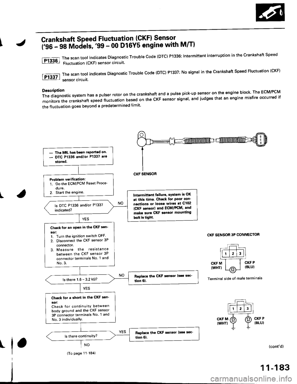
\Crankshaft Speed Fluctuation (GKFI Sensor .
firC- 48 Models, '99 - 00 D16Y5 engine with M/Tl
The scan tool indicates Diagnostic Trouble Code (DTC) P1336; Intermiftent interruption in the Crankshaft Speed
Fluctuation (CKF) sensor circuit.
ThescantooIindicatesDiagnosticTroub|ecode{DTC)P1337:NosignaIinthecrankshaftspeedF|uctuation(cKF}
sensor circuit.
D6scription
Thediagnosticsystemhasapu|serrotoronthecrankshaftandapu|sepick-upsensorontheengineblock.TheEcM/PcM
monitors the crankshaft speed ftuctuation based on the cKF sensor signal, and judges that 8n engine misfire occurred if
the fluctuation goes beyond a predetermined limit'
I
fPrk6l
lFr3g7-l
CKF SENSOR 3P CONNECTOR
L:l.)l l.' -Ir-T--T---.]l1 l2l3llL-''---r
CKFM I I CKFP
twrfit 1,.^ | lsLul\.7
Terminal side of male terminals
CKF MIWHT}
CKF PIBLUI
I(cont'd)
- The MtL hds been reported on.- DTC P1336 and/or P1337 a.e
stored.
P.oblem v€rific.tion:1. Do the ECM/PCM Reset Proce-
dure.2. Stan the enginelntormittont lailur6, tY3tom b OK
at thit tima. Chock tor Poor con'
nactions or loota wito! at C102
IC-KF son$rl .nd ECt /PCM, and
mrka suro CKF tonaor mounting
boh ittigM.
Chock for .n open in tho CKF aen-
30t:1. Turn the ignition switch OFF
2. Disconnect the CKF sensor 3P
connector,3. Measure the resista nce
between the CKF sensor 3P
connector terminals No. 1 and
No.3.
ls there 1.6- 3.2 kO?
Ch€ck tor a short in the CKF son'
30tiCheck {or continuitY between
body ground and the CKF sensor
3P connector termin6ls No. 1 and
No.3 individuallY.
(To page 11 184)
1 1-183
Page 554 of 2189
\
\
(From page 11-284)
\(cont'd)
11-285
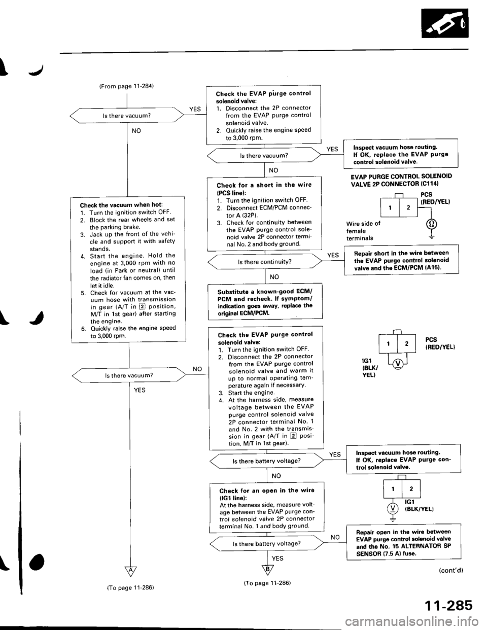
EVAP PURGE CONTROL SOI.INOID
VALVE 2P CONNECTOR IC114I
Wire side otfemaleterminals
?,
I,l,lil?"",,,u
EL,TWYEL)
Check the EVAP pirrge controlsolenoid valvei1. Disconnect the 2P connector
lrom the EVAP purge control
solenoid valve.
2. Ouickly raise the engine speed
to 3,000 rpm.
ls there vacuum?
InsDect vacuum ho56 routing.ll OK, replace the EVAP Purgecontrol solenoid valve.
Chock for a short in the wire(PCS linel:1. Turn the ignition switch OFF
2. Disconnect ECM/PCM connec'
tor A (32Pi.
3. Check for continuity between
the EVAP PUrge control sole
noid valve 2P connector termi
nal No.2 and body ground.
Check the vacuum when hot:
1. Turn the ignition switch OFF
2. Block the rear wheels and set
the parking brake.3. Jack up the front o{ the vehi-
cle and support it with safety
stands,4. Start the engine. Hold the
engine al 3,000 rpm wlth no
load (in Park or neutral) until
the radiator fan comes on, then
let it idle.5, Check for vacuum at the vac-
uum hose with transmissaonin gear (A/T in B Position,M/T in lst gear) after starting
the engrne.6. Ouickly raise the engine speed
to 3,000 rpm.
Reoair short in the wire botween
the EVAP purg€ cor|t]ol solenoid
valve and the ECM/pcM lA15l.ls there continuity?
Substitute a known-good ECM/
PCM and recheck. lf sYmPtom/indication goes eway. repl.c€ the
original ECM/PCM.
Check the EVAP Purg€ control
solenoid valve:1. Turn the ignition switch OFF
2. Disconnect the 2P connector
from the EVAP Purge control
solenoid valve and warm lt
up to normal operating tem_perature again if necessary
3. Stan the engine.4. At the harness side, measure
voltage between the EVAP
Purge control solenoid valve
2P connector terminal No. 1
and No. 2 with the transmission in gear (A,/T in E Posi-tion, M/T in 1st gear).
In3pect vacuum ho3€ touting.
ll OK, replace EVAP Purge con-
lrol aolenoid vtlv€.
Check lo. an open in the wire
llGl linel:At the harness side, measure volt
age between the EVAP Purge con-
trol solenoid valve 2P connectorterminal No. 1 and body groundRepeir open in tho wire between
EVAP purge conttol solenoid valv€
and the No. 15 ALTERNATOR SP
SENSOR (7.5 A fu3e
IBLK/YELI
lTo page 11 286i(To page 11-286)
Page 559 of 2189
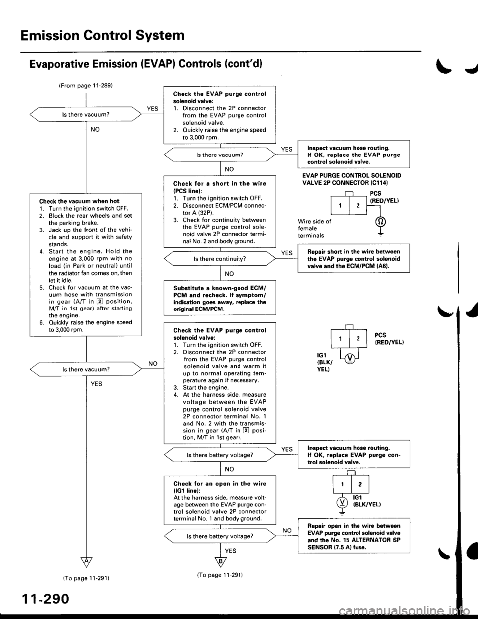
Emission Control System
Ch€ck the EVAP purge controlsolenoid valv6:1. Disconnect the 2P connectorfrom the EVAP purge controlsolenoid valve.2. Ouickly raise the engine speedto 3,000 rpm.
Insped vacuum hose routing.lf OK. roplace the EVAP purge
control solonoid valve.
Chock tor r short in the wir€
{PCS line):1. Turn the ignition switch OFF.2. Disconnect ECM/PCM connec-tor A (32P).
3- Check tor continuity betweenthe EVAP purge control sole-noid valve 2P connector termi-nal No. 2 and body ground.
Check the vacuum when hot:1. Turn the ignition switch OFF.2. Block the rear wheels and setthe parking brake.3. Jack up the lront of the vehi-cle and support it with safetystands.4. Start the engine. Hold theengine at 3,000 rpm with noload (in Park or neutrali until
the radiator fan comes on, thenlet it idle.5. Check for vacuum at the vac-uum hose with transmissionin gear (A/T in E position,
lvl/T in 1st gear) after startingthe engine.6. Ouickly raise the engine speedto 3,000 rpm.
Rooair shoft in the wire belwegnthe EVAP pulg6 control solenoidvalvs and tho ECM/PCM {A61.ls there continuity?
Substitute a known-good ECM/PCM and rech6ck. lt 3ymptom/indicrtion 90e3 rway, r6plac6 th€o.iginal ECM/FCM.
Check th€ EVAP purge controlsolenoid valve:1. Turn the;gnition switch OFF.2. Disconnect the 2P connectorfrom the EVAP purge controlsolenoid valve and warm itup to normal operating tem-perature again if necessary.3. Start the engine.4- At the harness side, measurevoltage between the EVAPpurge control solenoid valve2P connector terminal No. 1and No.2 with the transmis-sion in gear {A/T in E posi-tion, M/T in lst geari.
In3pect vacuum hoae routing.lf OK, repl.ce EVAP purge con-trol solonoid valve.ls there battery voltage?
Chock for an open in the wire(lG1 lina):At the harnoss side, measure volt-age beNveen the EVAP purge con-trol solenoid valve 2P connectorterminal No. 1 and body ground.
Repair open in the wire b€lwe€nEVAP purge contrl 3olenoid valv6and lhe No. 15 ALTERNATOR SPSENSOR 17.5 A, fu3e.
ls there battery voltage?
Evaporative Emission (EVAPI Controls (cont'dl
(From page 11-289)
(To page 11-291)
11-290
IJ
EVAP PURGE CONTROL SOLENOIDVALVE 2P CONNECTOR IC114I
PCS
IRED/YEL)
temaletermrnars
of
PCS(RED/YEL)
tGlIBLK/YEL)
{To page 11 291)
Page 597 of 2189
T
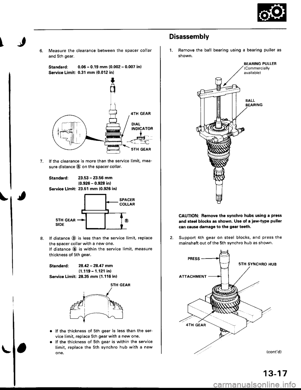
6. Measure the clearance between the spacer collar
and sth gear.
Standard: 0.06 - 0.19 mm 10.002 - 0.007 inl
Service Limit: 0.31 mm (0.012 inl
4TH GEAR
DIALINDICATOR
I
-<=q,
7.
5TH GEAR
lf the clearance is more than the service limit, mea-
sure distance @ on the spacer coilar
Standard: 23.53 - 23.56 mm
10.926 - 0.928 in)
Sowice Limit 23.51 mm {0.926 in}
SPACERCOLLAR
sTH GEARSIDE
lf distance @ is less than the service limit, replace
the spacer collar with a new one,
lf distance @ is within the service limit, measure
thickness of 5th gear.
Siandatd:28.1:2 - 28.17 mm
11.119 - 1.121 in)
Servica Limit: 28.35 mm (1.116 inl
sTH GEAR
lf the thickness of 5th gear is less than the ser-
vice limit, replace sth Oear with a new one.
lf the thickness of sth gear is within the service
limit, replace the 5th synchro hub with a new
one.
Disassembly
1. Remove the ball bearing using a bearing puller as
shown.
BEARING PULLER(Commercially
availablel
CAUTION: Remov€ ths synchro hubs using a press
and steel blocks as shown. Us€ of a iaw-type pullel
can caus€ damage lo the gear teeih.
Support 4th gear on steel blocks. and press the
mainshaft out of the sth svnchro hub as shown.
{cont'd)
13-17
Page 598 of 2189
Mainshaft Assembly
Disassembly (cont'd)
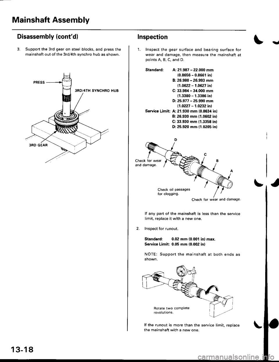
3. Support the 3rd gear on steel blocks, and press the
mainshaft out of the 3rd/4th synchro hub as shown.
13-18
Inspection
'1. Inspect the gear surface and bearing surface for
wear and damage. then measure the mainshaft atpoints A, B, C, and D.
Siandard: A: 21.987 - 22.000 mm
10.8656 - 0.8661 inl
B: 26.980 - 26.993 mm
11.0622 - 1.0627 inl
C: 33.98,1- 34.000 mm(1.3380 - 1.3385 in)
D: 25.977 - 25.990 mm
|.1.0227 - 1.0232 inl
Service Limit: A: 21.930 mm 10.8634 inl
B: 26.930 mm {1.0602 in}
C: 33.930 mm (1.3358 in)
D: 25.920 mm (1.0205 in)
Check for wear and damage
lf any part of the mainshaft is less than the service
limit, replace it with a new one.
2. Inspect for runout.
Standardi 0.02 mm (o.(Xtl in) max.
S€rvice Limii: 0.05 mm (0.002 in)
NOTE: Support the mainshaft at both ends as
snown.
lf the runout is more than the service lirnit, reolace
the mainshaft with a new one.
Y
Page 599 of 2189
I
)r'
Reassembly
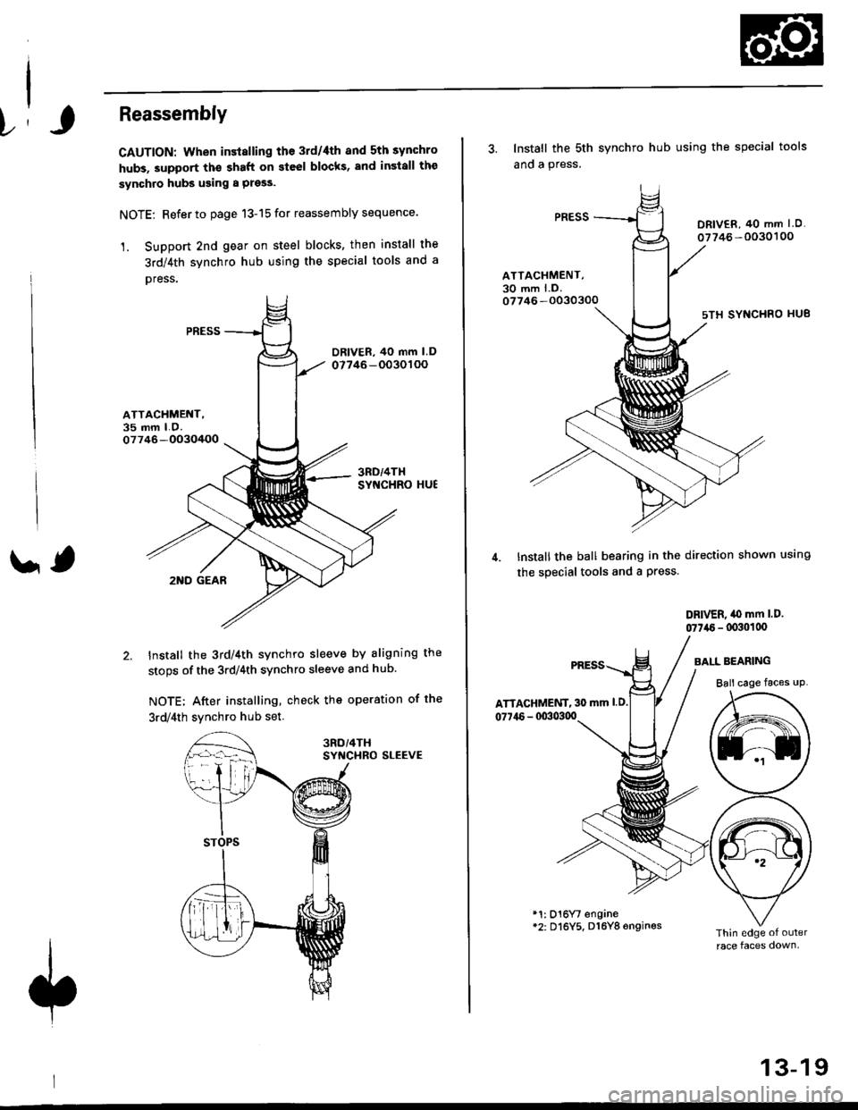
CAUTION: When installing the 3rd/4th and 5th synchro
hubs, support th€ shaft on steel blocks, and insiall the
synchro hubs using a press.
NOTE: Refer to page 13-15 for reassembly sequence.
1. Support 2nd gear on steel blocks' then install the
3rd/4th synchro hub using the special tools and a
oress.
ATTACHMENT,35 mm LO.07746-OO3O/+OO
' ,2I{D GEAR
Install the 3rd/4th synchro sleeve by aligning the
stops of the 3rdl4th synchro sleeve and hub.
NOTE; After installing, check the operation of the
3rd/4th svnchro hub set
SYf{CHRO SLEEVE
3. Install the sth
ano a press.
synchro hub using the special tools
DRIV€R, 40 mm I O.
07746 -0030'�100
ATTACHMENT,30 mm l.D.07746 -O030300
sTH SYNCHRO HU8
Install the ball bearing in the direction shown using
the special tools and a Press.
DRIVER, iO mm l.D.
07746 - lxxlollx'
ATTAGHMENT, 30 mm l.D.
077i16 - 00303qt
BAI-L BEARING
Ball cage faces uP
*1: D16Yt engane*2: Dl6Y5, D16Y8 6ngines
13-19
Page 602 of 2189
Countershaft Assembly
Disassembly
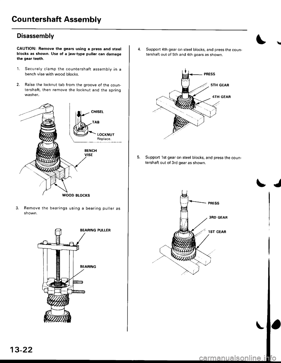
CAUTION: Remove the gears using a press and steelblocks as shown. Use of a iaw-type puller can damagethe gear teeth.
1. Securely clamp the countershaft assembly in a
bench vise with wood blocks.
2. Raise the locknut tab from the groove of the coun-
tershaft, then remove the locknut and the springwasher.
3.Remove the bearings using a bearing puller as
shown.
EEARING PULLER
\
4. Support 4th gear on steel blocks, and press the coun-tershaft out of 5th and 4th gears as shown.
Support 1st gear on steel blocks, and press the coun-
tershaft out of 3rd gear as shown.
5.
I./
3RD GEAR
1ST GEAR
Page 603 of 2189
Inspection
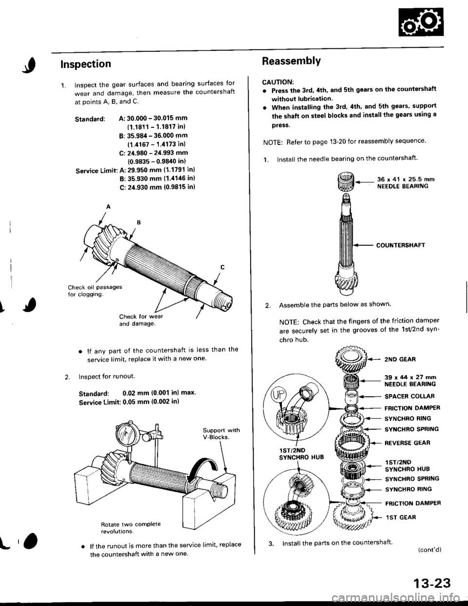
1.surfaces lor
countershaftInspect the gear surfaces and bearang
wear and damage, then measure tne
at points A, B, and C.
Standard: A: 30.000 - 30.015 mm
(1.1811- 1.1817 inl
B: 35.984 - 36.000 mm
(1.i1167 - 1.4173 inl
C: 24.980 - 2i1.993 mm
{0.9835 - 0.9840 in)
Seryice Limit: A: 29.950 mm (1.1791 inl
B: 35.930 mm (1 '1146 in)
C: 24.930 mm 10.9815 in)
Check oil passages
for cloggrng-
ICheck for wearano oamage.
. lf any part of the countershaft is less than
service limit, replace it with a new one.
Inspect for runout.
Standard: 0.02 mm (0.001 inl max.
Seryice Limit: 0.05 mm {0'002 in)
. lf the runout is more than the service limit. replace
the countershaft with a new one.
the
2.
t,3. Install the parts on the countershait
Reassembly
CAUTION:
. Press the 3rd,4th, and sth gears on the countershaft
without lubrication.
. When installing the 3rd. 4th, and 5th geals, support
the shaft on steel blocks and installthe gears using a
pless.
NOTE: Reler to page 13-20 for reassembly sequence'
1. lnstall the needle bearing on the countershaft'
, 36x41 x 25.5mmNEEDLE BEARING
COUNTERSHAFT
2. Assemble the pans below as shown.
NOTE: Check that the fingers of the friction damper
are securely set in the grooves of the 1sv2nd syn-
chro hub.
2ND GEAR
39x/+4x27mmNEEDLE BEARING
SPACER COLLAR
FRICTION DAMPER
SYNCHRO RING
SYNCHRO SPRING
REVERSE GEAR
lST/2NOSYNCHRO HUB
SYNCHRO SPRING
SYNCHRO RING
FRICTION DAMPER
1ST GEAR
(cont'd)
13-23
Page 651 of 2189
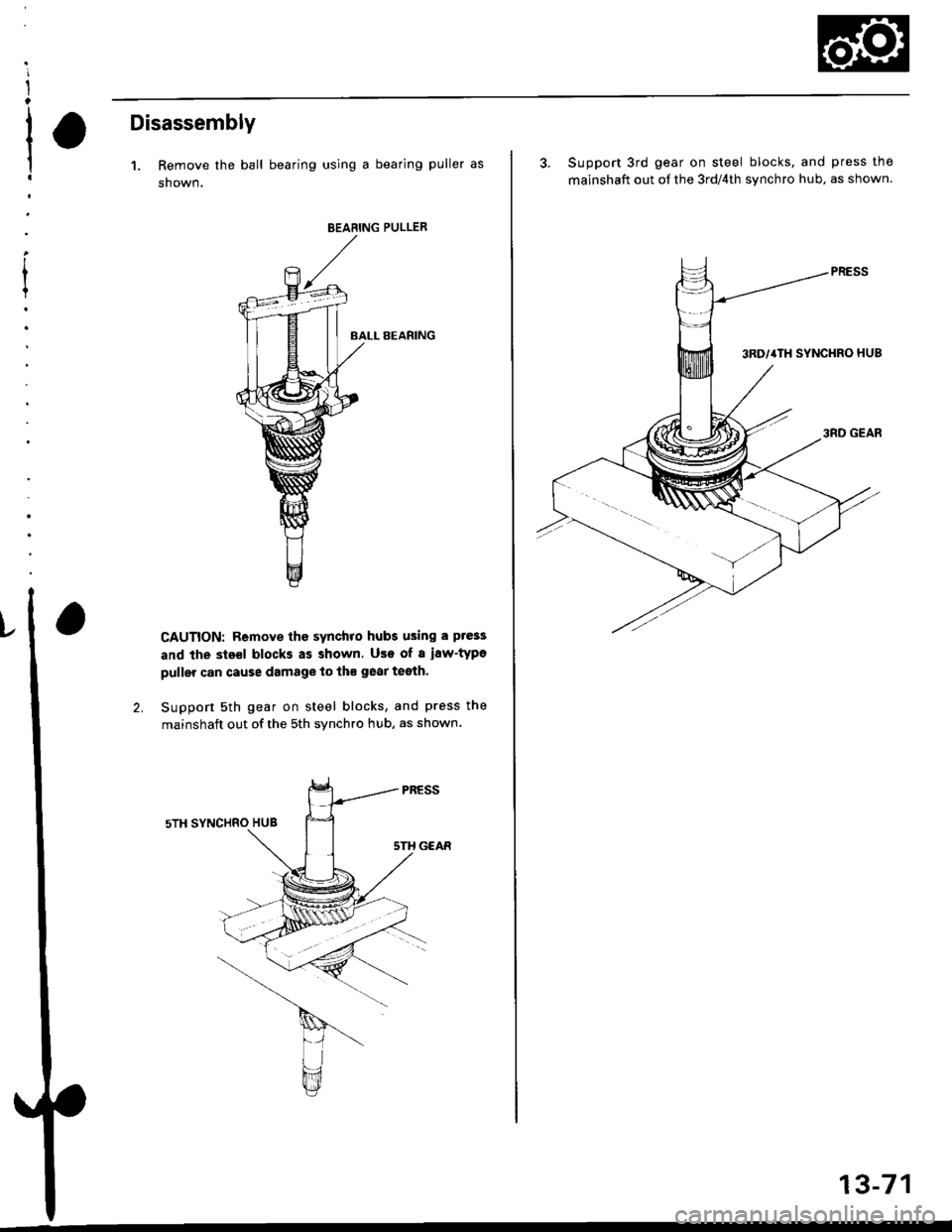
Disassembly
1. Remove the ball bearing using a bearing puller as
shown.
BEABING PULLER
BALL BEARING
CAUTION: Remove the synchro hubs using a ptess
and the sts€l blocks as shown. Use of a i8w'type
puller can cause damage to th€ gear teeth.
Support sth gear on steel blocks, and press the
mainshaft out of the sth synchro hub, as shown.
3. Support 3rd gear on steel blocks, and press the
mainshaft out of the 3rd/4th svnchro hub, as shown.
13-71
Page 653 of 2189
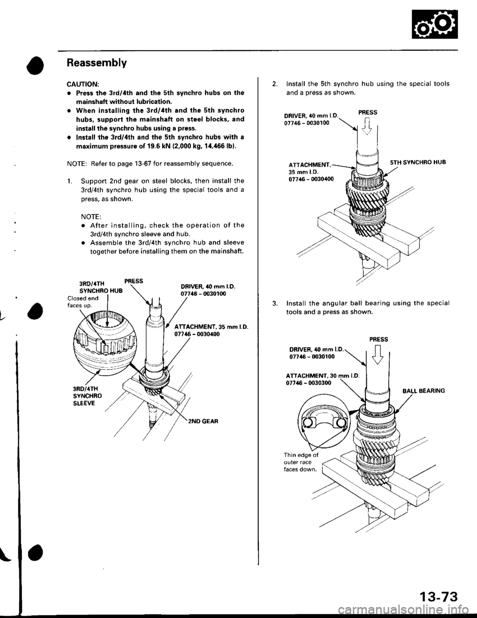
Reassembly
CAUTION:
. Press the 3rd/4th and the 5th synchro hubs on the
mainshaft without lubrication.
o When installing the 3rd/,lth and the sth synchro
hubs, support the mainshaft on steel blocks, and
installthe synchro hubs using a prsss.
. Install the 3rd/4th and the sth synchro hubs with a
maximum plessur€ of 19.6 kN (2,000 kg, 14,466 lbl.
NOTE: Refer to page 13-67 for reassembly sequence.
1, Support 2nd gear on steel blocks, then install the
3rd/4th synchro hub using the special tools and a
press, as snown.
NOTE:
. After installing. check the operation of the
3rd/4th synchro sleeve and hub.
. Assemble the 3rd/4th synchro hub and sleeve
together betore installing them on the mainshaft.
Closed end
3RD/4THSYNCHRO HU3DBIVER, 10 mm l.O.07746 - 00301U)
/ lrrlcHlileNr. ss .- t.o.07746 - 0030,100
l.
3RD/{THSYNCHROSLEEVE
2ND GEAR
2. Install the sth synchro hub using the special tools
and a press as snown.
DRIVER, {0 mm l.O.07746 - 0030100
ATTACHMENT,35 mm LD.
sTH SYNCHRO HUB
07716 - 0030,100
3. Install the angular ball bearing using the special
tools and a press as shown.
PRESS
+
DRIVER, 40 mm LD.0?7a6 - It030100