Block port HONDA CIVIC 1999 6.G Workshop Manual
[x] Cancel search | Manufacturer: HONDA, Model Year: 1999, Model line: CIVIC, Model: HONDA CIVIC 1999 6.GPages: 2189, PDF Size: 69.39 MB
Page 43 of 2189
Lift and SupPort Points
L,O
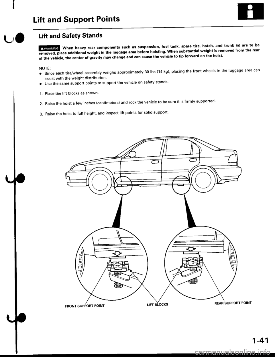
Lift and SafetY Stands
t!ffi when heavv rear components such as suspension' fuel tank' spare tire' hatch' and trunk lid are to be
-aEremoved, place additional wetght Inihe luggage arga before hoisting. when substantial weight is lemoved from the rear
of the vehicls. the center of gravity may change and can cause the vehicle to tip tolward on the hoisi
NOTE:
. Since each tire/wheel assembly weighs approximately 30 lbs (14 kg)' placing the front wheels in the luggage area can
assist with the weight distribution
. Use the same support points to suppon the vehicle on safety stands'
Place the lift blocks as shown.
Raise the hoist a lew inches (centrmeters) and rock the vehicle to be sure it is firmly supported'
Raise the hoist to full height, and inspect lift points for solid support
1.
2.
3.
REAR SUPPORT POINT
1-41
Page 44 of 2189
Lift and Support Points
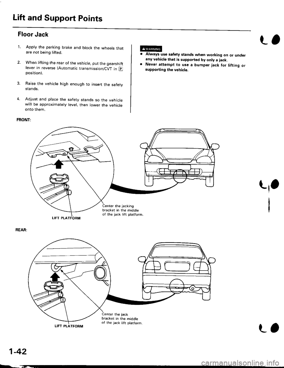
Floor Jack
Apply the parking brake and block the wheets thatare not being lifted.
When lifting the rear of the vehicle, put the gearshiftlever in reverse (Automatic transmission/Cw in Eposition).
Raise the vehicle high enough to insert the safetystands.
Adjust and place the safety stands so the vehiclewill be approxlmately level, then lower the vehicleonto them.
FRONT:
Always use safety stands whon working on or undelany vehicle that is supported by only a iack.Never attempt to use a bumper jack for lifting orsupporting the vehicle.
t,1.
REAR:
1-42
LIFT PLA
4.
Center the jacking
bracket in the middleof the iack lift platform.
Center the iackbracket in the middleof the jack lift ptatform.
-,-_
LIFT PLATFORM
L,
Page 148 of 2189
6, Remove the camshaft holders. then measure the
widest ponion of the plastigage on each journal.
Camshaft-to-Holder Oil Clearance:
Standard lNew):0.050 - 0.08!t mm
{0.002 - 0.004 in}
Service Limit : 0.15 mm {0.006 in)
lf the camshaft-to-holder oil clearance is out ot tol-
erance:- And the camshaft has already been replaced,
you must replace the cylinder head.
- lf the camshaft has not been replaced, first check
the total runout with the camshaft supported on
V-blocks.
Camshaft Total Runout:
Standard (New): 0.03 mm (0.001 inl max.
Service Limit: 0.04 mm {0.(X)2 in)
-7.
Rotate camshattwhile measuring.
L
- lf the total runout of the camshaft is within toler-
ance, replace the cylinder head.
- lf the total runout is out of tolerance, replace the
camshaft and recheck the camshaft-to-holder oil
clearance. lf the oil clearance is still out of toler-
ance. replace the cylinder head.
INTAKEEXHAUST
O16Y/ engine35.299 (1.3897)37.281 (1.4678)
D16Y5
engrne
PRI38.427 11.5129138.784 (1.5269)
SEC32.193 (1.2674)
D l6Y8
engrne
PRI36.77811.44791
38.008 (1.4964)MID38.274 (1.5068)
sEu37.065 (1.4592)
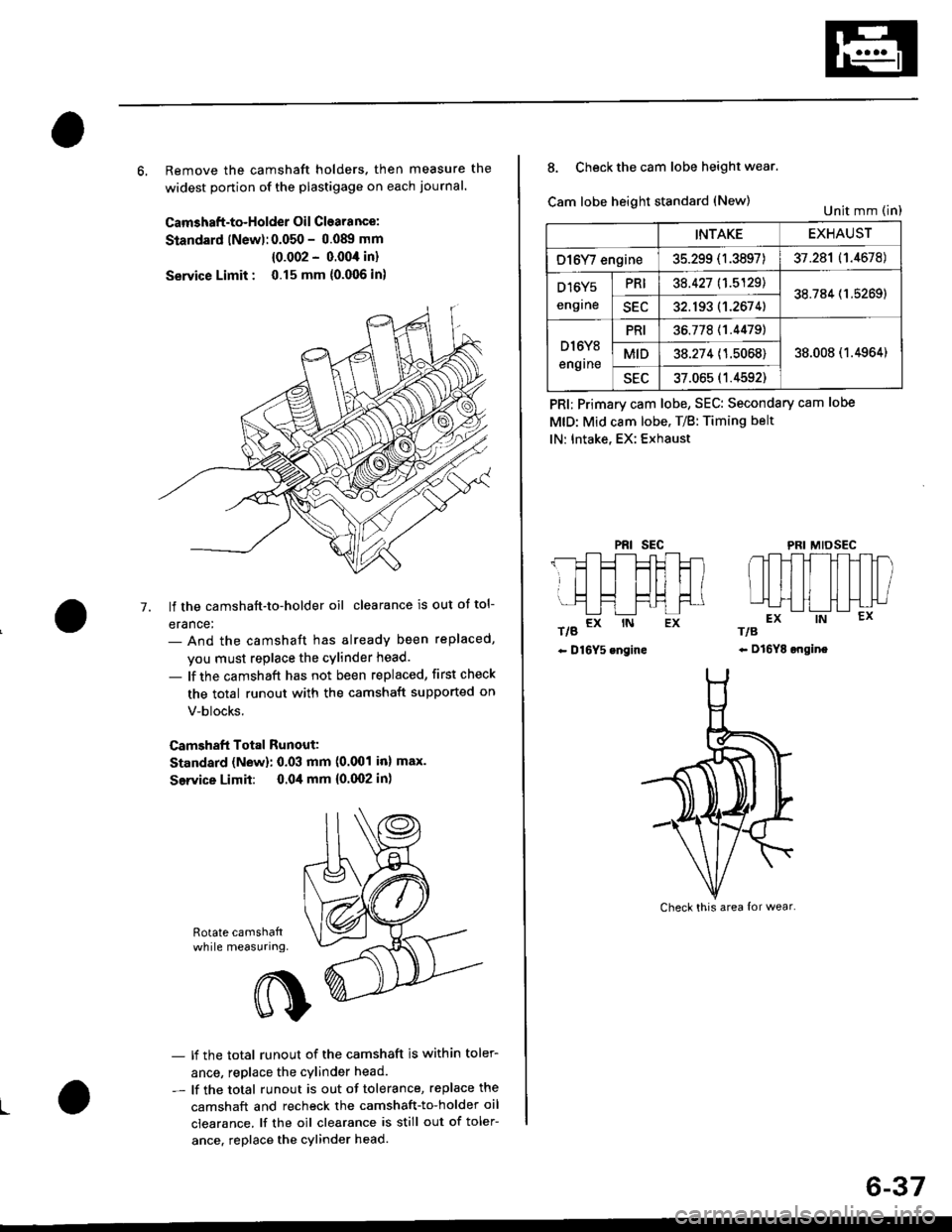
8. Check the cam lobe height wear.
Cam lobe height standard (New)
t/g a* rN Ex
- D16Y5 engine
PRI; Primary cam lobe, SEC: Secondary cam lobe
MtD: Mid cam lobe. T/B: Timing belt
lN: Intake, EX: Exhaust
PRIsEcMIDSEC
rts
- Dl6YE ongine
Unit mm (in)
Check this area {or wear.
6-37
Page 186 of 2189
Gamshafts
Inspection (cont'dl
7. lf the camshaft-to-holder oil clearance is out of tol-
erance:
- And the camshaft has already been replaced, you
must replace the cylinder head.- lf the camshaft has not been replaced, first check
the total runout with the camshaft supported on
V-blocks.
Camshaft Total Runout:
Standard (New): 0.03 mm {0.001 in} max.
Service Limit: 0.04 mm (0.002 inl
- lf the total runout of the camshaft is within toler,
ance, replace the cylinder head.- lf the total runout is out of tolerance. replace the
camshaft and recheck the camshaft to,holder oil
clearance. lf the oil clearance is still out of toler-
ance, replace the cylinder head.
INTAKEEXHAUST
PRIMARY33.088 mm
{1.3027 in)
32.785 mm
(1.2907 inl
MID36.267 mm(1.4278 in)
35.720 mm
{1.4063 in)
SECONDARY34.978 mm(1.3771 inl
3i1.691 mm(1.3658 in)
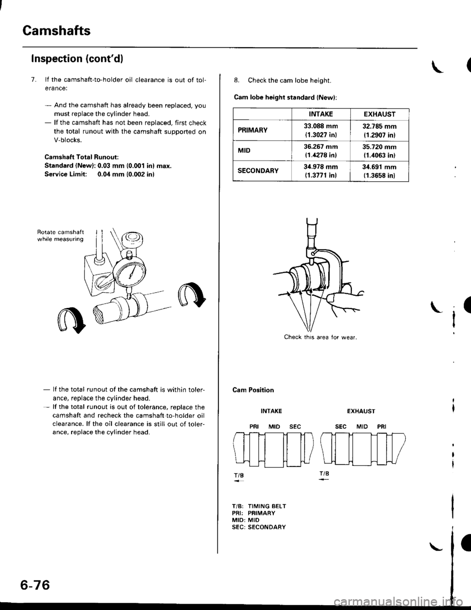
8. Check the cam lobe height.
Cam lobe height standard (New):
Cam Position
I
INTAKE
MID
EXHAUST
SEC MID PRI
TIB
T/B: TIMING BELTPRI: PRIMARYMID: MID
Check thrs area lor wear.
Page 201 of 2189
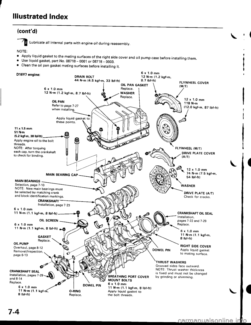
lllustrated Index
(cont'dl
I Luoricate att internal parts with engine oil during reassembly.
NOTE:
' Apply liquid gasket to the mating surfaces ofthe rightside coverand oil pumpcase before installingthem.. Use liquid gasket, part No. 08718 - 0001 or 087,18 _ OOO3.. Clean the oil pan gasket mating surfaces before installing it.
D16Y7 engine:6 x 1.0 mm12 N.m (1.2 kgt.m.8.7 tbf.tr)DRAIN BOLT44 N.m {4.5 kgt.m.33 tbt.ttl
,(
I
I
OIL PAN GASKETFLYWHEEL COVERIM/T)6x 1.0 mm12 N.m ('l .2 kgt.m, 8.7 tbt.trl
OIL PANRefer to page 7-27
Apply liquid gasker tothese points.
Replace.
WASHERReplace.12 x '1.0 mm118 N.m{12.0 kgt.m, 87 tbf.tr}
11 x 1.5 mm51 N.m15.2 kgl.m,38lbtftl
Apply engine oilto the boltthreads.NOTE: After torquingeach cap, turn the crankshaftto check for binding.
MAIN BEARINGSSelection, page 7-10
MAIN BEARING CAP
CRANKSHAFTInstallation, page 7 23
NOTE: New main bearings mustbe selected by matching crankand block identification markings.
6 r 1.0 mm11 N.m {1.1
6 x 1.0 mm11 N.m 11.1
ksI.m, 8 lbt.ft)
OIL SCREEN
kgt.m, 8 lbf.trl
Check for cracks.
CRANKSHAFT OIL SEALInstallation,pages 1 22 a^d 7-29
\:eprace'
GASKETReplace.
6 x 1.O mm11 N.m {1.1 kgt.m,8 rbt.frl
RIGHT SIDE COVERApply liquid gasker1o matrng surface,
OIL PUMPOverhaul, page 8-12Bemoval/lnspection,page 8-13
DOWEL PIN
WASHERSGrooved sides face outward.NOTE: Thrust washer thicknessis fixed and must not be changedby grinding or shimming.
CRANKSHAFT SEAL
l.j"Ji:l"^ pages z.2e --.S)
Replace.
6 x 1.0 mm11 N.m {1.18 tbt.fr)
7-4
BREATHING PORT COVERMOUNT BOLTS6 x 1.0 mm11 N.m {1.1 kgt.m, 8 tbf.fr}Apply liquid gasker tothe boh threads.
DOWEL PIN
Page 211 of 2189
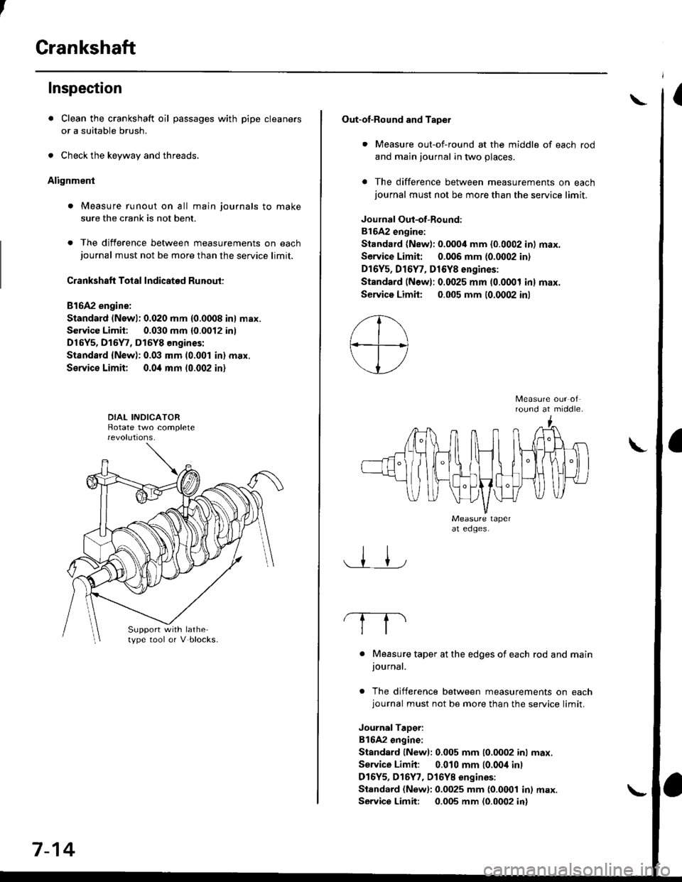
Crankshaft
Inspection
. Clean the crankshaft oil passages with pipe cleaners
or a suitable brush.
. Check the keyway and threads.
Alignment
. Measure runout on all main journals to make
sure the crank is not bent.
. The difference between measurements on eachjournal must not be more than the service limit.
Crankshaft Total Indicated Runout:
Bl6A2 engine:
Standard (Newl: 0.020 mm {0.0008 in} max.
Service Limit: 0.030 mm {0.0012 inl
D16Y5, D15Y7, D15Y8 engines:
Standsrd {New): 0.03 mm (0.001 in} max.
Service Limit; 0.0i1 mm 10.002 in)
Support with lathetype tool or V blocks.
7-14
Out-of-Round and Tapet
. Measure out-of-round at the middle of each rod
and main journal in two places.
a The difference between measurements on eachjournal must not be more than the service limit.
Joulnal Out-of-Round:
81642 engine:
Standard (New): 0.0004 mm {0.0002 in) max.
Service Limit: 0.006 mm {0.0002 in)
Dr6Y5, Dl6Y7, D16Y8 engines:
Standard (Newl: 0.0025 mm (0.0001 inl max.
Service Limh: 0.005 mm (0.0002 inl
round at middle.
. Measure taper at the edges of each rod and mainjournal.
. The difference between measurements on eachjournal must not be more than the service limit.
JournalTaDer:
B16A2 ongine:
Standard lNewl: 0.005 mm (0.0002 inl max.
Service Limit: 0.010 mm (0.00i1 inl
D16Y5, D16Y7, Dl6YB engines:
Standard (New): 0.0025 mm {0.0001 in) max.
Service Limit: 0.005 mm (0.0002 in)
\
Page 214 of 2189
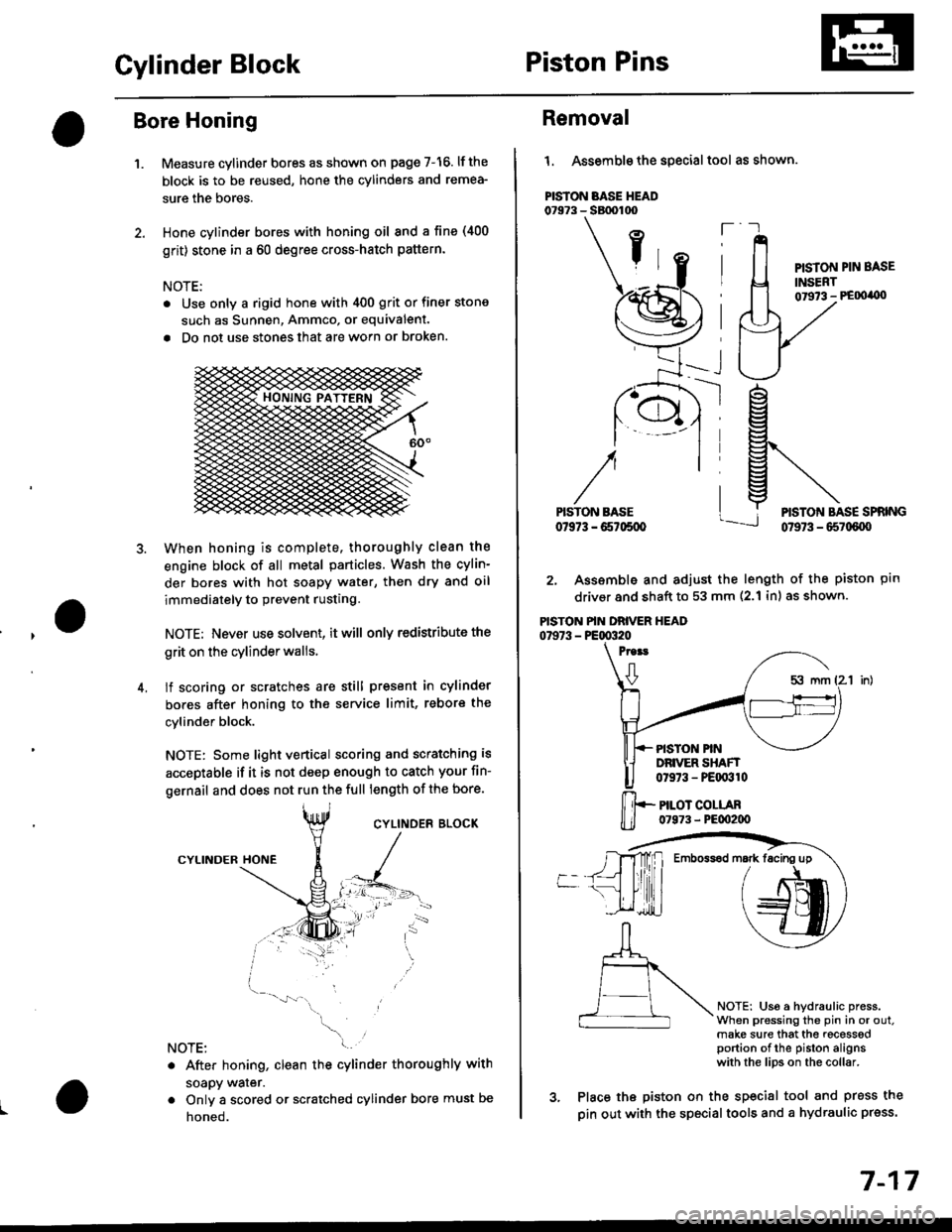
Cylinder BlockPiston Pins
Bore Honing
1.Measure cylinder bores as shown on page 7-16. lf the
block is to be reused, hone the cylinders and remea-
sure the bores.
Hone cylinder bores with honing oil 8nd a fine (400
grit) stone in a 60 degree cross-hatch pattern.
NOTE:
. Use only a rigid hone with 400 grit or finer stone
such as Sunnen, Ammco, or equivalent.
. Do not use stones lhat are worn or broken.
When honing is complete, thoroughly clean the
engine block of all metal particles. Wash the cylin-
der bores with hot soapY water, then dry and oil
immediately to prevent rusting.
NOTE: Never use solvent. it will only redistribute the
grit on the cylinder walls.
lf scoring or scratches are still present in cylinder
bores after honing to the service limit, rebore the
cylinder block.
NOTE: Some light vertical scoring and scratching is
acceptable if it is not deep enough to catch your fin-
gernail and does not run the full length of the bore.
CYLINOES BLOCK
CYLINDER
NOTE:
. After honing, clean the cylinder thoroughly with
soapy warer.
. Onlv a scored or scratched cylinder bore must be
noneo.
Removal
l. Assemble the special tool as shown.
PISTON BASE HEAD07973 - SBtx)too
ft
PISTON PIN BASE
INSERT01973 - PE00'0)
ptn
NOTEi Us6 a hydraulic press.When pressing the pin in or out.make sure that the recesssdportion of the piston alignswith the lips on the collar.
rg
g\
lj*N*,""
2. Assemble and adjust the length of the piston
driver and shaft to 53 mm (2.1 inl as shown.
PISTON PIN DRIVER HEAD07973 - PE00320
Proat
0
PISTON PINDRIVER SHAFT0t973 - PEqr310
PILOT COLLAR07973 - PE00200
3. Place the piston on the sp€cial tool and press the
pin out with the special tools and a hydraulic press.
Emboss6d mark facing up
7-17
Page 384 of 2189
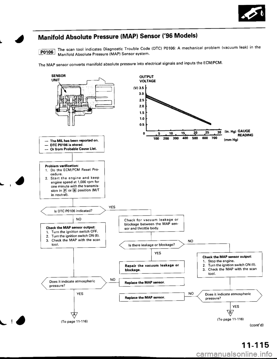
Manifold Absolute Pressure (MAP) Sensor ('96 Models)
The scan tool indicates Diagnostic Trouble Code (DTC) P0106: A mechanical problem (vacuum leak) in the
Manifold Absolute Pressure (MAP) Sensor system'
TheMAPsensorconvertsmanifoIdabsoIutepressureintoeiectricaIsigna|sandinpUtstheEcM/PcM'
OUTPUTVOLTAGE
(v13.5
3.0
2.5
2.0
1.5
1.0
0.5
0lin. Hgl GAUGE
- The MIL has been reported on- OTC P0106 is storod.- Or from Ptobable Cause Lisl.
Problom verificetion:1. Do the ECM/PCM Reset Pro-
cedure.2. Start the engine and keep
engine speed at 1,000 rpm for
one minute with the transmis'
sion in @ or I Position {Mff
in neutral).
ls DTC P0106 indicated?
Check tor vacuum leakage or
blockage between the MAP sen'
sor and throftle bodyCheck the MAP sensor outPut:
1. Turn the ignition switch OFF
2. Turn the ignition switch ON (ll).
3. Check the MAP with the scan
tool.ls there leakage or blockage?
Chock the MAP s€nsol output:
1. Stop the engane.2. Turn the ignition switch ON (ll).
3. Check the MAP with the scan
tool.
READING300(mm Hgl
(To page 11 116)
{cont'd)ll,(To page 11-116)
1 1-1 15
Page 445 of 2189
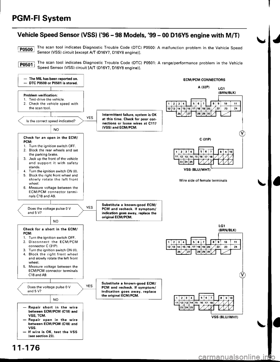
PGM-FI System
Vehicle Speed Sensor (VSSI ('96 - 98 Models,'99 - 00 D16Y5 engine with M/Tl
@The scan tool indicates Diagnostic Trouble Code (DTC) P0500: A malfunction problem in the Vehicle SpeedSensor (VSS) circuit Iexcept A!/T (D16Y7, D16Y8 engine)1.
The scan tool indicates Diagnostic Trouble Code (DTC) P0501: A range/performance problem in the VehicleSpeed Sensor (VSS) circuit [A,rT {D16Y7, D16Y8 engine)].
ECM/PCM CONNECTORS
A {32P} LG.t
VSS IBLU/WHT}
Wire side ot temale terminals
LGI(BRN/8LK}
The MIL has been reDorted on.DTC P0500 or P0501 is stored.
Problem verification:1- Test drive the vehicle.2. Check the vehicle speed withthe scan tool.
Intermittent tailure, system is OKat this time. Check tor Door con-nections or loose wires at C117{VSSland ECM/PCM.
ls the correct speed indicated?
Check for an open in the ECM/PCM:1. Turn the ignition switch OFF.2. Elock the rear wheels and setthe parking brake.3. Jack up the front of the vehicleand support it with safetystands.4. Turn the ignition switch ON (ll).
5. Block the right tront wheel andslowly rotate the left front
6, Measure voltage between theECM/PCM connector termi-nals C18 and A9.
Subslitute a known-good ECM/PCM and recheck. lf symptom/indic.tion goes away, replace theorisinal ECM/PCM.
Does the voltage pulse 0 Vand 5 V?
Check tor a short in ihe ECM/PCM:1. Turn the ignition switch OFF.2. Disco n n ect the ECM/PCMconnector C (31P).
3. Turn the ignition switch ON {ll).4. Block the right front wheeland slowly rotate the left front
5. Measure voltage between theECM/PCM connector terminalsC18 and A9.
Substitute a known-good ECM/PCM and recheck. lI symptom/indication goes away. replacethe original ECM/PCM.
Does the voltage pulse 0 Vand s V?
- Repair short in the wirebetwGen ECM/PCM {C18} endvss, TcM.- Repair open in the wirebetween ECM/PCM {Cl8} andvss.- lf wire is OK, test the VSSlsee section 23).
{BRN/BLK}
239l0lt
121611t8t9202321
2A2930
c {31P}
I38191o
tl12ialr5i6l10./
I2356a9l011
12l3l5t61tl8t920222a
27202930
12910
t2l13l.l7I l,/ 1,/231r.lslt., ),rlL
VSS {BLU/WHT}
11-176
Page 446 of 2189
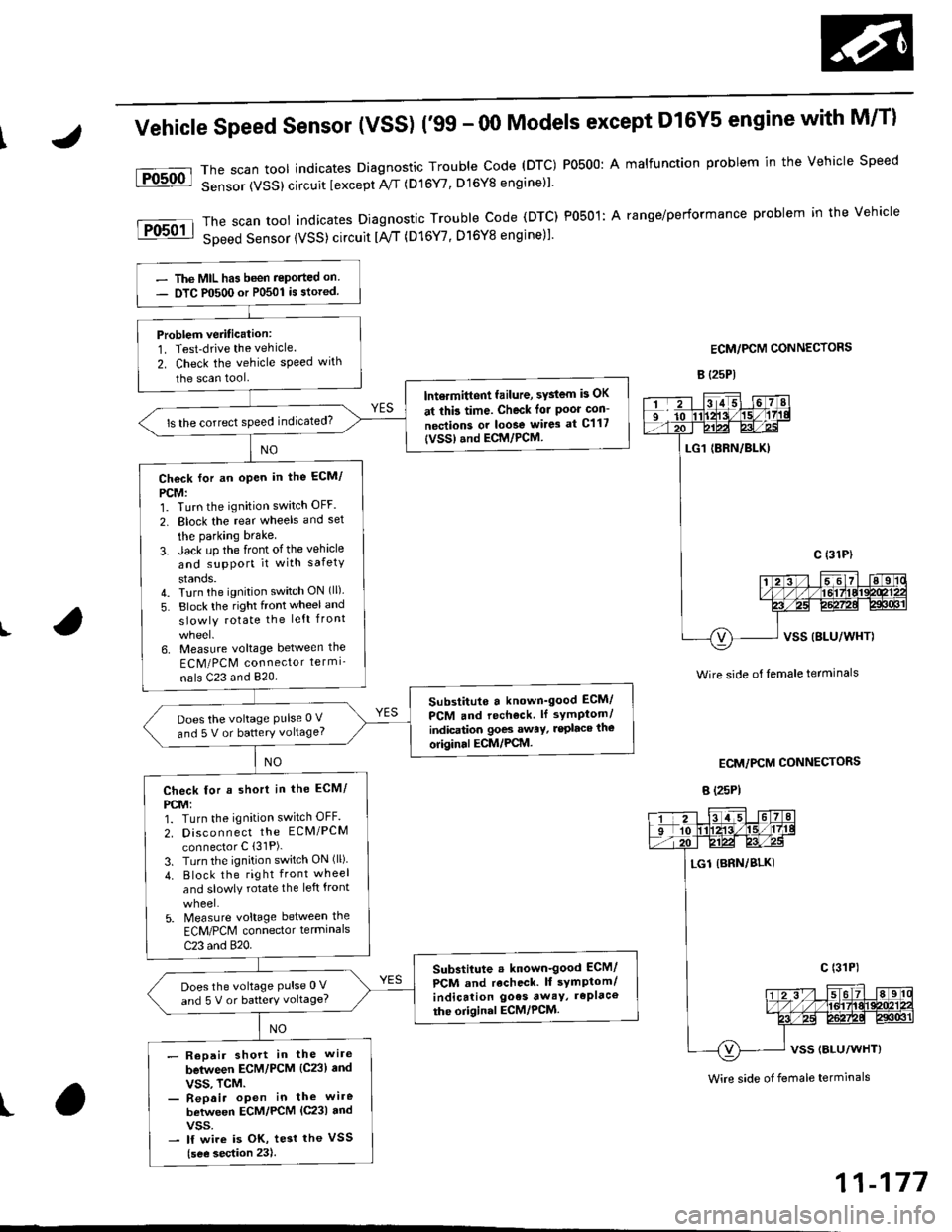
fFosoo-l
lFosoil
Vehicle Speed Sensor (VSS) ('99 - 00 Models except Dl6Y5 engine with M/T)
Thescantoo|indicatesDiagnosticTroub|ecode(DTc)Po5o0:Ama|functionproblemintheVehic|espeed
Sensor (VSS) circuit lexcept A//T (D16Y/, D16Y8 engine)l'
Thescantoo|indicatesDiagnost|cTroub|eCode(DTC)Po5o1:Arange/performanceprob|emintheVehicle
SDeed Sensor {VSS) circuit tA,/T (D16Y7, D16Y8 engine)1.
ECM/PCM CONNECTORS
B {25P)
I
t
Wire side ol lemale terminals
ECM/PCM CONNECTORS
B E5PI
The MIL has been reported on
OTC P0500 or P0501 is stored.
Problem veritication:1. Test-drive the vehicle.
2. Check the vehicle speed with
the scan tool
lntermitt6nt failure, sYstem is OK
at thb time. Check tor Poor con-
nections or loose wir6 at C117
{vss} .nd ECM/PCM
ls the correct sPeed indicated?
Check for an open in the ECM/
PCM:1. Turn the ignition switch OFF.
2. Block the rear wheels and set
the parking brake
3. Jack uP the front ofthe vehicle
and support it with safety
stands.4. Turn the ignition switch ON (ll).
5. Block the right front wheel and
slowly rotate the left front
6, Measure voltage between the
ECM/PCM connector termi_
nals C23 and 820.
Substituto a known'good ECM/
PcM and rech€ck. ll sYmptom/
indic€tion goes awaY, lsplace the
original ECM/PCM.
Does the voltage Pulse 0 V
and 5 V or battery voltage?
Check for a short in the ECM/
PCM:1. Turn the ignition switch OFF.
2. Disco n n ect the EcM/PcM
connector C (31P).
3. Turn the ignition switch ON (ll)
4. Block the right front wheel
and slowly rotate the left front
5. Measure voltage between the
ECM/PCM connector terminals
C23 and 820.
Substiiute . known-good ECM/
PCM and r6check. lf symptom/indication goes awaY, rePlace
the origin.l ECM/PCM.
Does the voltage Pulse 0 V
and 5 V or battery voltage?
- Reoair short in the wire
between ECM/PCM {C23} and
vss. TcM.- Repai. open in the wire
between ECM/PCM {C231 andvss.- lf wire is OK, tesr the VSS
{see sestion 23).
Wire side oI female terminals
11-177