rear seal HONDA CIVIC 1999 6.G User Guide
[x] Cancel search | Manufacturer: HONDA, Model Year: 1999, Model line: CIVIC, Model: HONDA CIVIC 1999 6.GPages: 2189, PDF Size: 69.39 MB
Page 1188 of 2189
Rear Brake Caliper
Reassembly (cont'dl
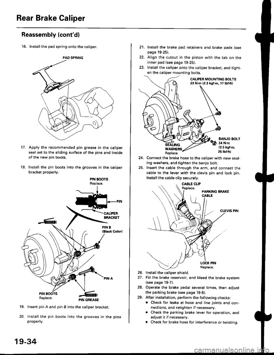
'16. Installthe pad spring onto the caliper.
Apply the recommended pin groase in the caliper
seal set to the sliding surface of the pins and inside
of the new pin boots.
Install the pin boots into the grooves in the caliper
bracket properly.
PIN BOOTSReplsce.
(Bl.ck Colorl
PINRepl6ce.
19. Insert pin A and pin B into the caliper bracket.
20. Install the pin boots into the grooves in thepropefly.
PAD SPRING
11.
PIN GREASE
19-34
pr ns
22.
21. Install the brake pad retainers and brake pads (see
page 19-25).
Align the cutout in the piston with the tab on the
inner pad (see page 19-25).
Install the caliper onto the caliper bracket. and tight-
en the caliper mounting bolts.
CALIPER MOUNTING BOLTS23 N.m {2.3 kg{.m. 17 lbf.ft)
WASHERSReplace.
BANJO BOLT34 N.m13.5 kg{.m.25 rbtft)
24.Connect the brake hose to the caliper with new seal,
ing washers, and tighten the banjo bolt,
Insert ths cable through the arm, and connect the
cabls to the lever with the clevis pin and lock pin.
Install the cable clip securely.
CLEVIS PIN
-t
//t
LOCK PINRoplace.
26. Install the caliDer shield.
27. Fill the brake reservoir, and bleed the brake svstem(see page 19-71.
28. Operate the brake pedal several times, then adjust
the parking brake (see page 19-6).
29. After installation, perform the following checks:. Check for leaks at hose and line joints and con-nections, and retighten if necessary.. Check the parking brake lever for operation, and
adjust it if necessary.
. Check for brake hose for interference or twistinq.
Page 1255 of 2189
|}Mirror Holder/Cover Replacement
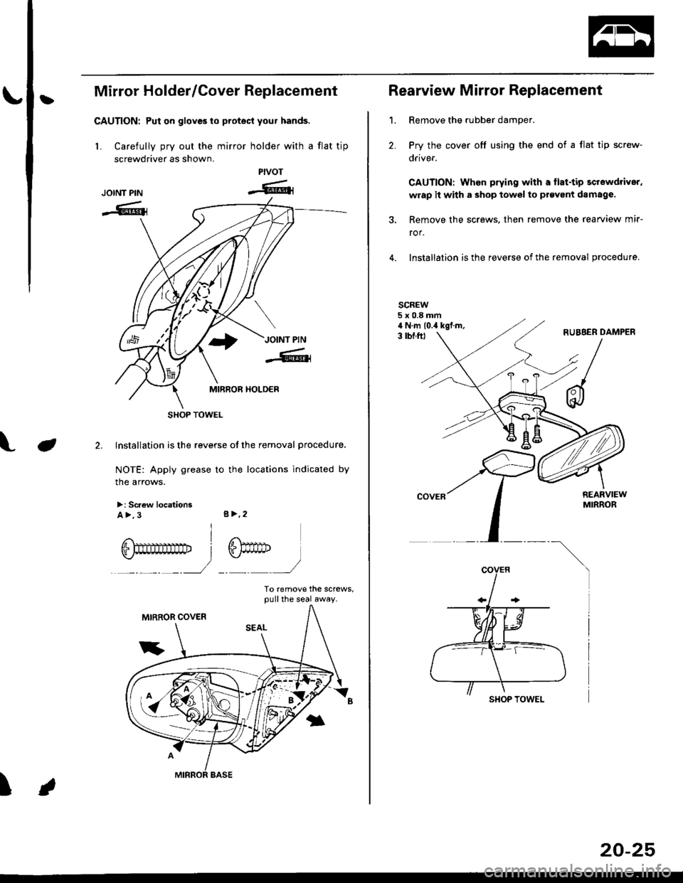
CAUTION: Put on gloves to protecl your hands.
L Carefully pry out the mirror holder with a flat tip
screwdriver as shown.
Installation is the reverse of the removal procedure.
NOTE: Apply grease to the locations indicated by
the arrows.
>: Sc.ew locationsA >, 3 s>,2
I
ry
To remove the screws,pull the seal away.
PIVOT
-6rJOINT PIN
-G{
J
6)drD
)
I
SHOP TOWEL
Rearview Mirror Replacement
1. Remove the rubber damper.
2. Pry the cover off using the end of a flat tip screw-
drivef.
CAUTION: When prying with a flat-tip screwdriver,
wrap it with a shop towel to prgvant damage.
3. Remove the screws, then remove the rearview mir-
ror,
4. Installation is the reverse of the removal procedure.
SCREW5x0.8mmil N.m lo.a kgf.m,3 lbf.ftl
SHOP TOWEL
20-25
Page 1257 of 2189
b
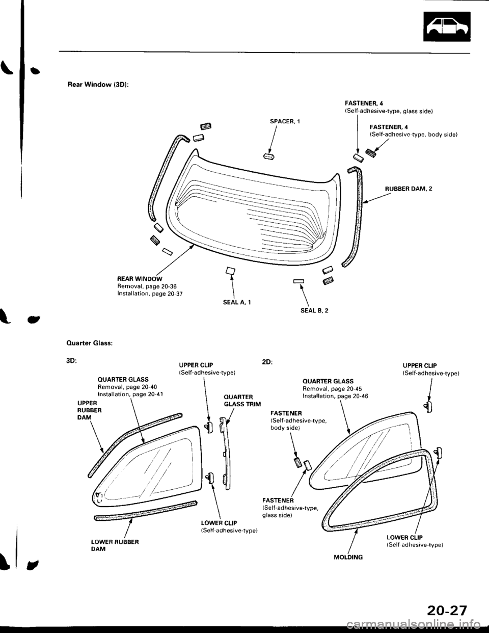
Rear Window l3Dl:
SPACER,
I
| ,o"r.".". o
{ff*'*'YPe
bod'side)
FASTENER,4(Self-adhesive-type, glass side)
RUBBER DAM,2
tIISEAL A, 1
=@
SEAL B, 2
e
Ouarter Glass:
3D:
OUARTER GLASSRemoval, page 20-40Installation, page 20 4lOUARTERGLASS TRIM
LOWER CLIPlSelf adhesive'type)
2D:
FASTENER(Self-adhesive-type,glass side)
FASTENER(Self-adhesave type,body side)
\
\
)f\
n,
$(
\il]
LOWER RUBBERDAM
LOWER CLIP(Self adhesive-type)
J
20-27
Page 1261 of 2189
3
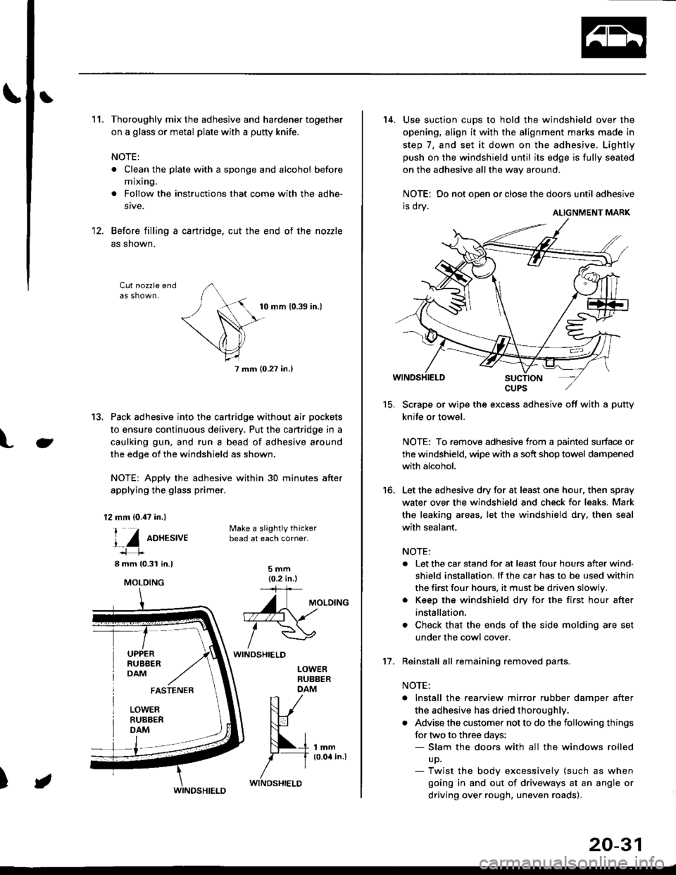
11.Thoroughly mix the adhesive and hardener together
on a glass or metal plate with a putty knife.
NOTE:
. Clean the plate with a sponge and alcohol before
mixing.
. Follow the instructions that come with the adhe-
stve.
Before filling a cartridge. cut the end of the nozzle
as shown.
Cut nozzle end
tu
10 mm 10.39 in.)
7 mm (0.27 in.l
13. Pack adhesive into the cartridge without air pockets
to ensure continuous delivery. Put the cartridge in a
caulking gun, and run a bead of adhesive around
the edge of the windshield as shown.
NOTE: Apply the adhesive within 30 minutes after
applying the glass primer.
12 mm (0.47 in.)
l_Z oo*.t,ut
8 mm 10.31 in.l
UPPERRUBBERDAM
Make a slightly thickerbead at each corner.
5mm(0.2 in )='+
A\uloto^o. -.\
/wWINDSHIELD
LOWEBRUBBERDAM
lmm10.04 in.l
FASTENER
LOWERRUBBERDAM
)
MOLDING
WINDSHIELD
20-31
15.
16.
14. Use suction cups to hold the windshield over the
opening, align it with the alignment marks made in
step 7, and set it down on the adhesive. Lightly
push on the windshield until its edge is fully seated
on the adhesive all the way around.
NOTE: Do not open or close the doors until adhesive
ri vI Y ALTGNMENT MARK
Scrape or wipe the excess adhesive off with a putty
knife or towel.
NOTE: To remove adhesive from a painted surface or
the windshield, wipe with a soft shop towel dampened
with alcohol.
Let the adhesive dry for at least one hour, then spray
water over the windshield and check for leaks. Mark
the leaking areas, let the windshield dry, then seal
with sealant.
NOTE:
. Let the car stand for at least four hours after wind-
shield installation. lf the car has to be used within
the first four hours, it must be driven slowly.
. Keep the windshield dry for the first hour after
installation.
. Check that the ends of the side molding are set
under the cowl cover.
Reinstall all remaining removed parts.
NOTE:
. Install the rearview mirror rubber damper after
the adhesive has dried thoroughl',.
. Advise the customer not to do the following things
for two to three days:- Slam the doors with all the windows rolled
up.- Twist the body excessively (such as when
going in and out of driveways at an angle or
driving over rough, uneven roads).
't7.
Page 1265 of 2189
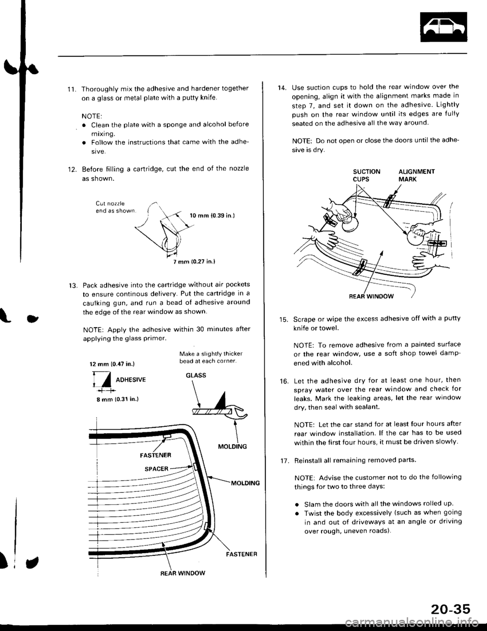
'11.Thoroughly mix the adhesive and hardener together
on a glass or metal plate wilh a putty knife.
NOTE:
. Clean the plate with a sponge and alcohol before
mixing.
. Follow the instructions that came with the adhe-
sive.
Before filling a cartridge, cut the end of the nozzle
as shown.
10 mm {0.39 in.)
7 mm (0.27 in.l
Pack adhesive into the cartridge without air pockets
to ensure continous delivery. Put the canridge in a
caulking gun, and run a bead ol adhesive around
the edge of the rear window as shown.
NOTE| Apply the adhesive within 30 minutes after
applying the glass primer.
12.
13.
J
12 mm 10.,U in.)
[/ oo*r.,u.
8 mm (0.31 in.)
Make a slightly thickerbead at each corner.
GLASS
FASTENER
SPACER
MOLDING
MOLDING
)REAR WINDOW
FASTENER
20-35
14. Use suction cups to hold the rear window over the
opening, align it with the alignment marks made in
step 7, and set it down on the adhesive. Lightly
push on the rear window until its edges are {ully
seated on the adhesive all the way around.
NOTE: Do not open or close the doors until the adhe-
sive is dry.
SUCTION ALIGNMENTCUPS MARK
Scrape or wipe the excess adhesive off with a putty
knife or towel.
NOTE: To remove adhesive from a painted surface
or the rear window, use a soft shop towel damp-
ened with alcohol.
Let the adhesive dry for at least one hour, then
spray water over the rear window and check for
leaks. Mark the leaking areas, let the rear window
dry, then seal with sealant.
NOTE: Let the car stand for at least four hours after
rear window installation. lf the car has to be used
within the Iirst tour hours, it must be driven slowly
Reinstall all remaining removed parts
NOTE: Advise the customer not to do the following
things for two to three days:
. Slam the doors with all the windows rolled up.
. Twist the body excessively (such as when going
in and out of driveways at an angle or driving
over rough. uneven roads).
16.
1-7 .
Page 1267 of 2189
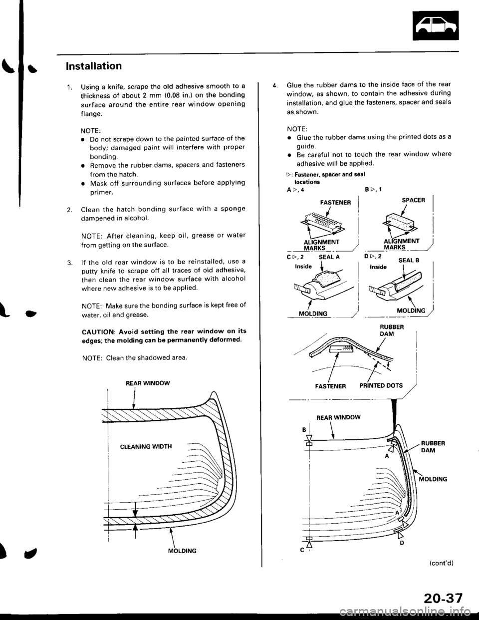
tlnstallation
'1.
3.
Using a knife, scrape the old adhesive smooth to a
thickness of about 2 mm (0.08 in.) on the bonding
surface around the entire rear window opening
flange.
NOTE:
. Do not scrape down to the painted surface ol the
body; damaged paint will interfere with proper
bonding.
a Remove the rubber dams, spacers and fasteners
from the hatch.
. Mask off surrounding surfaces before applying
primer.
Clean the hatch bonding surface with a sponge
dampened in alcohol.
NOTE: After cleaning, keep oil, grease or water
from getting on the surface.
lf the old rear window is to be reinstalled, use a
putty knife to scrape off all traces of old adhesive,
then clean the rear window surface with alcohol
where new adhesive is to be applied.
NOTE; Make sure the bonding surface is kept free of
water, oil and grease.
CAUTION: Avoid setting the rear window on its
edges; the molding can be permanently deformed.
NOTE: Clean the shadowed area
2.
O
)
REAR WINDOW
4. Glue the rubber dams to the inside face of the rear
window, as shown, to contain the adhesive during
installation, and glue the fasteners, spacer and seals
as shown.
NOTE:
. Glue the rubber dams using the printed dots as a
g u ide.
. Be careful not to touch the rear window where
adhesive will be aPPlied
>r Fastener, spacor and seallocations
A>,4B>, 1
SPACER
D> '2 'EAL B'W
/l
si
o.\6fif,", j
ryt48rq _ _ ,,/
-\l
19Pry/
FASTENER PRINTED DOTS
REAR WINDOW
MOLOING
(cont'd)
20-37
FASTENER
"-*^1
wAL.IGNMENT ]IIARKS _ _,/C>,2 SEAL A
Page 1270 of 2189
Rear WindowOuarter Glass
Installation {cont'd)
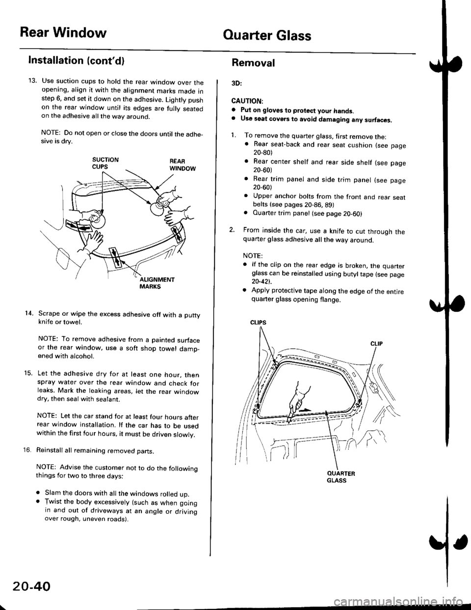
13. Use suction cups to hold the rear window over theopening. align it with the alignment marks made inslep 6. and set it down on the adhesive. Lightly pushon the rea. window until its edges are fully seatedon the adhesive allthe way around.
NOTE: Do not open or close the doors until the adhe_sive is drv.
sucTtoNCUPS
Scrape or wipe the excess adhesive off with a puttyknife or towel.
NOTE: To remove adhesive from a painted surfaceor the rear window. use a soft shop towel damp-ened with alcohol.
Let the adhesive dry for at least one hour. thenspray water over the rear window and check forleaks, Mark the leaking areas, let the rear windowdry, then seal with sealant.
NOTE: Let the car stand for at least four hours afterrear window installation. lf the car has to be usedwithin the first four hours, it must be driven slowly.
Reinstall all remaining removed parts.
NOTE: Advise the customer not to do the followingthings for two to three days:
. Slam the doors with all the windows rolled up.. Tr,vist the body excessively lsuch as when goingin and out of driveways at an angle or drivingover rough, uneven roads).
14.
15.
\
20-40
Removal
3D:
CAUTION:
a Pul on gloves to protect your hands.. Use seat covers to avoid damaging any surfaces,
1. To remove the quarter glass, first remove the:. Rear seat-back and rear seat cushion (see page20_80)
. Rear center shelf and rear side shelf lsee page20_60)
. Rear trim panel and side trim panel (see page20_60)
. Upper anchor bolts from the front and rear seatbelts {see pages 20-86. 89). Ouarter trim panel (see page20-60)
2, From inside the car, use a knife to cut through thequarter glass adhesive all the way around.
NOTE:
. lf the clip on the rear edge is broken, the quarterglass can be reinstalled using butyltape (see page20-421.
. Apply protective tape along the edge of the entirequarter glass opening flange.
OUARTERGLASS
Page 1272 of 2189
Quarter Glass
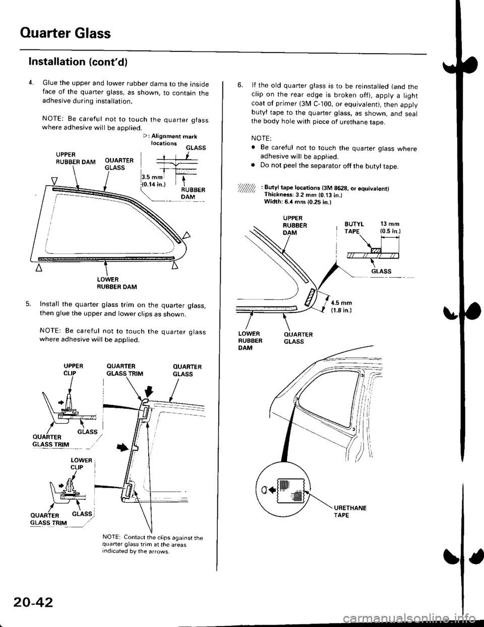
Installation (cont'd)
4. Glue the upper and lower rubber dams to the insideIace of the quaner glass, as shown, to contain theadhesive during installation.
NOTE: Be careful not to touch the quarter glasswhere adhesive will be applied.>: Alignment marklocationsGLASSUPPERRUBBER DAM
LOWERRUBEER DAM
Install the quarter glass trim on the quarter glass,then glue the upper and lower clips as shown.
NOTE: Be careful not to touch the quarter glasswhere adhesive will be applied.
OUARTERGLASS TRIMOUARTERGLASS
GLASS TRIM
NOTE: Contact the cljps against thequarter glass trim at the areasIndicated by the arrows.
UPPER
20-42
6. lf the old quarter glass is to be reinstalled (and theclip on the rear edge is broken off), apply a lightcoat of primer (3I/ C-100, or equivalent), then applybutyl tape to the quarter glass, as shown. and sealthe body hole with piece of urethane tape.
NOTE:
. Be careful not to touch the quaner glass whereadhesive will be applied,. Do not peel the separator offthe butyltape.
//////// '. 8�u'Jt tape tocarions t3M 8628, or equivetenrl' Thickness:3.2 mm lo.t3 in.lWidth: 6.4 mm {0.25 in.)
BUTYL 13 mmTAPE (0.5 in.l
\\l
,7r--/r4--;*--T-
.. GLASS
UPPERRUEBERDAM
Page 1281 of 2189
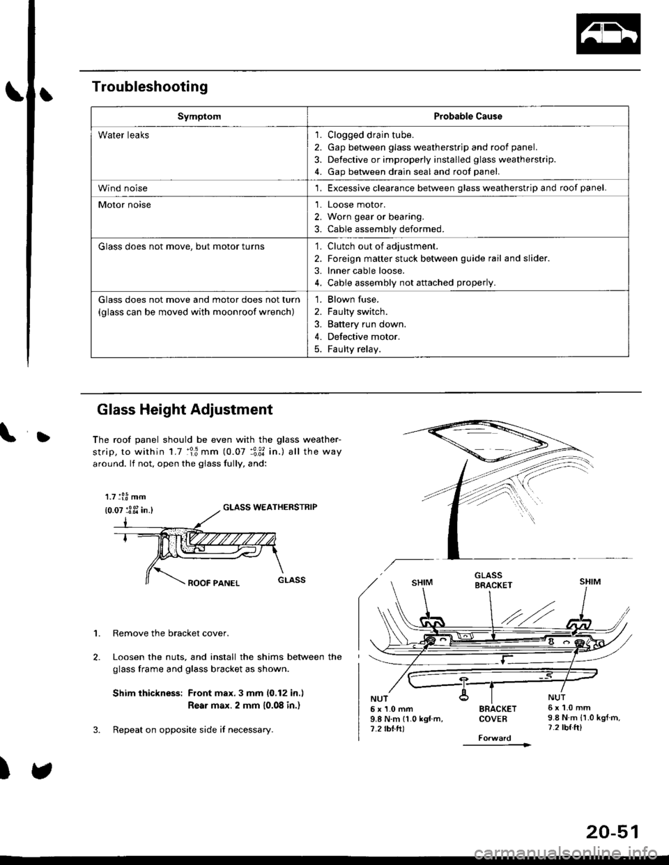
Troubleshooting
SymptomProbable Cause
Water leaks1. Clogged drain tube.
2. Gap between glass weatherstrjp and roof panel.
3. Defective or improperly installed glass weatherstrip.
4. Gap between drain seal and roof panel.
Wind noise'1. Excessive clearance between glass weatherstrip and roof panel.
Motor noise1. Loose motor.
2. Worn gear or bearing.
3. Cable assembly deformed.
Glass does not move, but motor turns'1. Clutch out of adjustment.
2. Foreign matter stuck between guide rail and slider.
3. lnner cable loose.
4. Cable assembly not attached properly.
Glass does not move and motor does not turn
{glass can be moved with moonroof wrench)
1. Blown fuse,
2. Faulty switch.
3. Battery run down.
4. Defective motor.
5. Faulty relay.
D
Glass Height Adjustment
The roof panel should be even with the glass weather-
strip, to within 1.7 :lr3 mm (0.07 :3:31 in.) all the way
around. lf not, open the giass fully, and:
GLASS WEATHERSTRIP
1. Remove the bracket cover.
Loosen the nuts, and install the shims between the
glass frame and glass bracket as shown.
Shim thickness: Front max.3 mm 10,12 in.l
Rear max. 2 mm 10.08 in.)
Repeat on opposite side i{ necessary.
)
5x1.0mm9.8 N.m 11.0 kgf m,7.2 rbtft)
SRACKETCOVEB
----------1>
6x1.0mm9.8 N.m {1.0 kgtm,7.2 tbf.ft)
1.7 tl.8 mm
{0.07 :3 3i in.}
20-51
Page 1285 of 2189
L
L
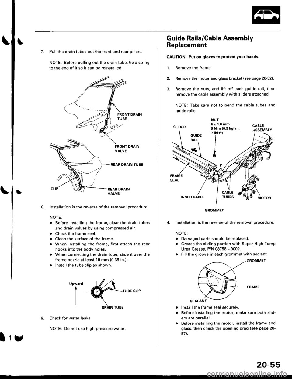
7. Pull the drain tubes out the front and rear pillars.
NOTE: Before pulling out the drain tube, tie a string
to the end of it so it can be reinstalled.
Installation is the reverse of the removal procedure.
NOTE:
. Before installjng the frame, clear the drain tubes
and drain valves by using compressed air.
. Check the frame seal.
. Clean the surface of the frame.
. When installing the frame, first attach the rear
hooks into the body holes.
. When connecting the drain tube, slide it over the
frame nozzle at least 10 mm (0.39 in.).
. Install the tube clip as shown.
UpwardI
I
I
TUBE CLIP
Check for water leaks.
NOTE: Do not use high-pressure water.
DRAIN TUBE
Ity
20-55
Guide Rails/Cable Assembly
Replacement
CAUTION: Put on gloves to protect your hands,
1. Remove the frame.
Remove the motor and glass bracket (see page 20-52).
Remove the nuts, and lift off each guide rail, then
remove the cable assembly with sliders attached.
NOTE: Take care not to bend the cable tubes and
guide rails.
Installation is the reverse of the removal procedure.
NOTE:
. Oamaged parts should be replaced.
. Grease the sliding portion with Super High Temp
Urea Grease, P/N 08758 - 9002.
. Fillthe groove in each grommet with sealant.
a
a
Install the frame seal securely.
Before installing the motor. make sure both slid-
ers are parallel.
Before installing the motor. install the frame and
glass, then check the opening drag (see page 20-
GROMMET