ac system HONDA CIVIC 1999 6.G Workshop Manual
[x] Cancel search | Manufacturer: HONDA, Model Year: 1999, Model line: CIVIC, Model: HONDA CIVIC 1999 6.GPages: 2189, PDF Size: 69.39 MB
Page 536 of 2189
1\
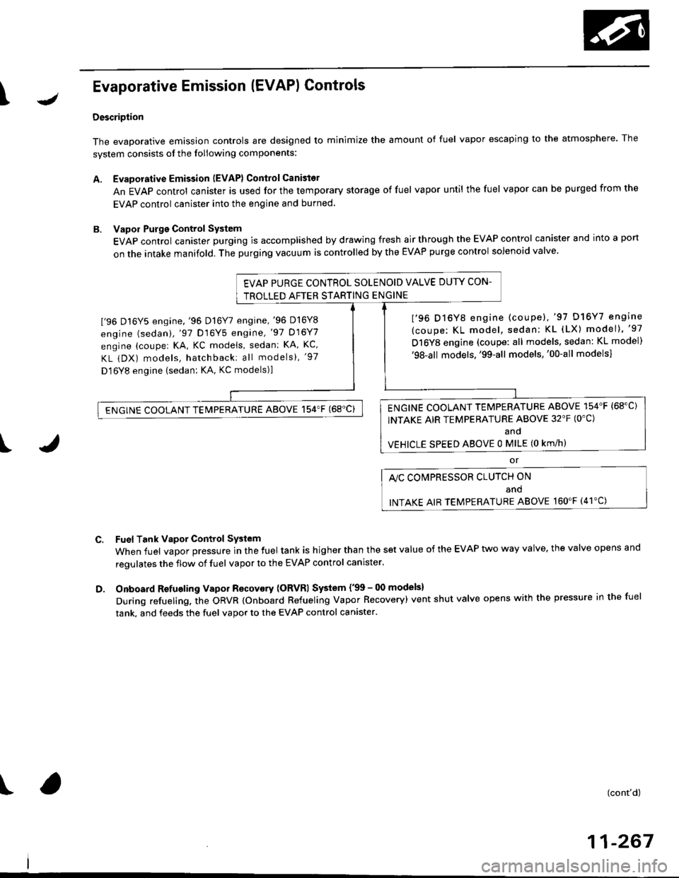
Evaporative Emission (EVAPI Controls
Description
The evaporative emission controls are designed to minimize the amount of fuel vapor escaping to the atmosphere. The
system consists of the foliowing components:
A. Evaporative Emission (EVAP) Control Canisto]
An EVAP control canister is used for the temporary storage of fuel vapor until the fuel vapor can be purged from the
EVAP control canister into the engine and burned.
B. Vapor Purge Control System
EVAP control canister purging is accomplished by drawing fresh air through the EVAP control canister and into a port
on the intake manifold. The purging vacuum is controlled by the EVAP purge control solenoid valve.
I'96 D16Y5 engine,'96 Dl6Y7 engine,'96 D16Y8
engine (sedan),'97 D16Y5 engine,'97 D16Y7
engine (couper KA, KC models, sedan: KA, Kc'
KL iDX) models, hatchback: all models), '97
D 16Y8 engine (sedan: KA, KC models)l
I'96 D16Y8 engine (coupe),'97 D16Y7 engine
(coupe: KL model, sedan: KL (LX) model)"97
D16Y8 engine (coupe: all models, sedan: KL model)'98-all models,'99-all models,'00-all modelsl
I
c.
D.
or
l'lc COMPRESSOR CLUTCH ON
and
INTAKE AIR TEMPERATURE ABOVE 160"F (41'C)
Fuel Tank Vapor Control System
When fuel vapor pressure in the fuel tank is higher than the set value of the EVAP two way valve, the valve opens and
regulates the flow of fuel vapor to the EVAP control canister.
Onboard Refueling Vapor Recovery (ORVRI System {'99 - 00 models}
During refueling. the oRVR {onboard Refueling Vapor Recovery) vent shut valve opens with the pressure in the fuel
tank. and feeds the fuel vapor to the EVAP control canister.
t(cont'd)
11-267
EVAP PURGE CONTROL SOLENOID VALVE DUTY CON-
TROLLED AFTER STARTING ENGINE
ENGINE COOLANT TEMPERATURE ABOVE 154'F {68"C)
INTAKE AIR TEMPERATURE ABOVE 32'F (O'C)
and
VEHICLE SPEED ABOVE O MILE (O KM/h}
ENGINE COOLANT TEMPERATURE ABOVE 154'F (68'C)
Page 537 of 2189
Emission Control System
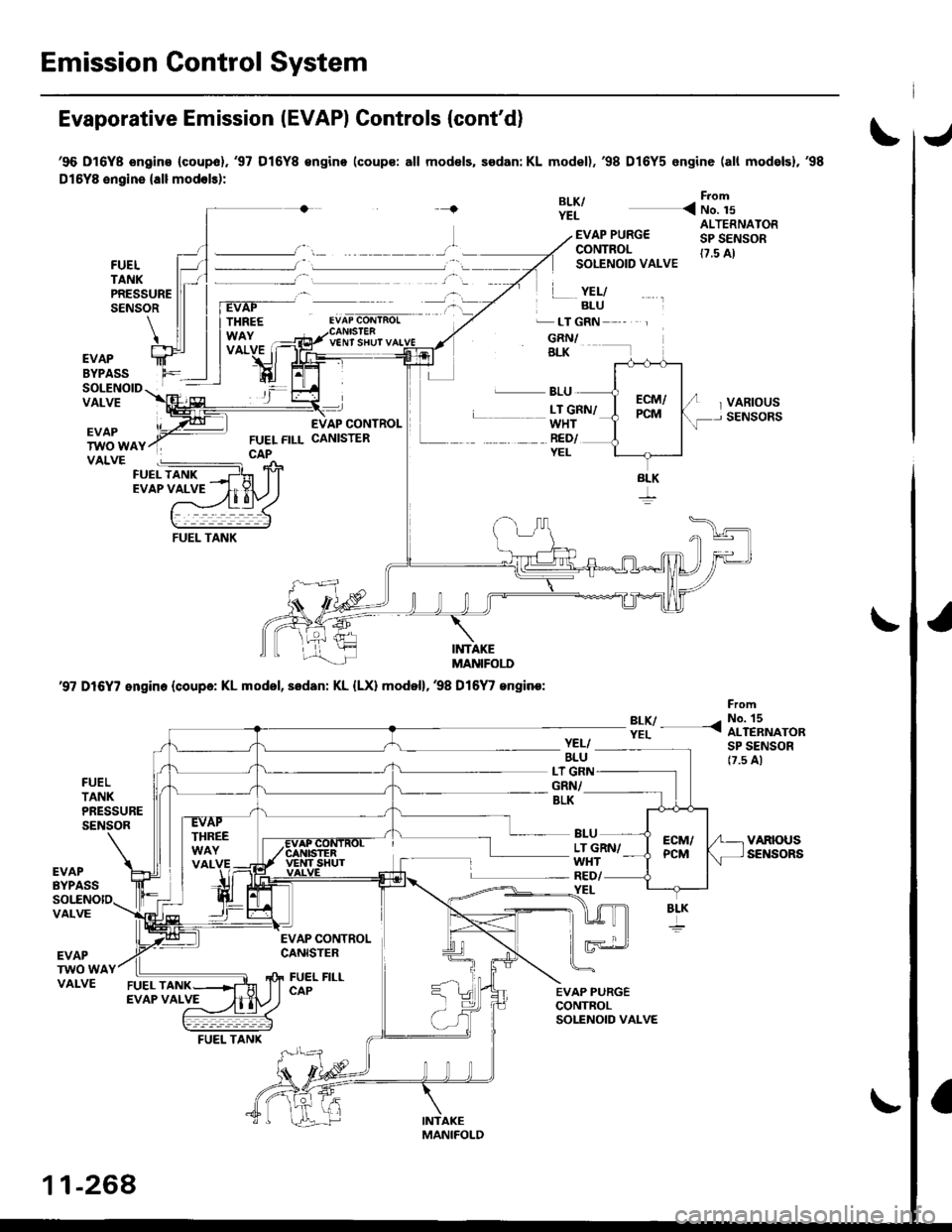
Evaporative Emission IEVAPI Controls (cont'd)
'96 D16Y8 ongins (coupol.'97 D16Y8 €ngino (coups: all mod€ls, sedan: KL model),'98 D16Y5 engine (all mod6lsl,'98
Dl5YB engine {all modols):
{BLK/YEL
From
< No. 15
FUELTANKPRESSURESENSOR
EVAP PURG€CONTROLSOLENOID VALVE
.� LT GRN
GRN/BLK
ALTERNATORSP SENSOR(7.5 A)
VARIOUSSENSORS
YEL/BLU
V€NT SHUT
EVAPBYPASSSOLENOIDVALVEL BLU
WHTRED/YEL
L __ LT GRN/
EVAPTWO WAYVALVE
INTAKEMANIFOI.I'
'97 D16Y7 engin. (coupa: KL model, sedan: KL {LX) model},38 Dl6
/ engine:
?:y- -<
FromNo. 15ALTERNATORSP SENSOR17.5 A)
FUELTANKPRESSURESENSOR
YEL/BLULT G]GRN/BLK
LT GRN/WHT
BLU
YEL
EVAPBYPASSRED/
VALVE
EVAPTWO WAVALVE
EVAP CONTROLCANISTER
FUEL FILLCAP
BLK
11-268
FUEL TANK
Page 539 of 2189
Emission Control System
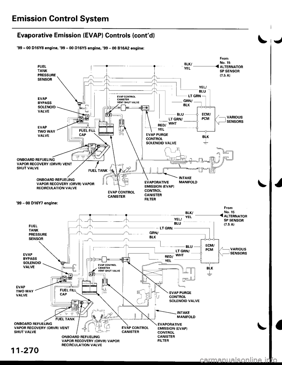
Evaporative Emission (EVAPI Controls (cont'd)
'99 - 00 Dl6Yg engine,'99 - 00 Dl6Y5 €ngine,'99 - 00 81642 engine:
FUELTANKPRESSURESENSOR
EVAPBYPASSSOLENOIDVALVE
From
BLK/ - No. 15
YEL _ ALTERNATORSP SENSOR
{7.5 A)
- GRN/BLK
BLU
*=ol
LT GRN/WHT
ONBOARD REFUELING
FUEL TANK
EVAP PURGECONTROLSOLENOID VALVE
EVAPORATIVEEMISSION {EVAP)CONTROLCANISTERFILTER
YEL
LT GRN
VAPOR RECOVERY IONVR) VENTSHUT VALVE
ONBOARD REFUELINGVAPOR RECOVERY IORVN} VAPORRECIRCULATION VALVE
'99 - 00 D16Y7 engine:
EVAP CONTROLCANISTER
BLK/YEL
FromNo. 15< ALTERNATORSP SENSOR{7.5 A}FUELTANKPRESSURESENSOR
EVAPEYPASSSOLENOIDVALVE
- BLULT GNN/WHT
EVAP PURGECONTROLSOLENOIO VALVE
INTAKEMANIFOLD
EVAPTWO WAYVALVE
FUEL TANK
ONBOARD REFUELINGVAPOR RECOVERY {ORVRI VENTSHUT VALVE
EVAPORATIVEEMISSION {EVAPICONTROL
EVAP CONTROL
ONBOARD REFUELINGVAPOR RECOVERY IORVRI VAPORRECIRCULATION VALVE
CANISTERFILTER
YELI
8LK
11-270
CANISTER
Page 540 of 2189
\J
\
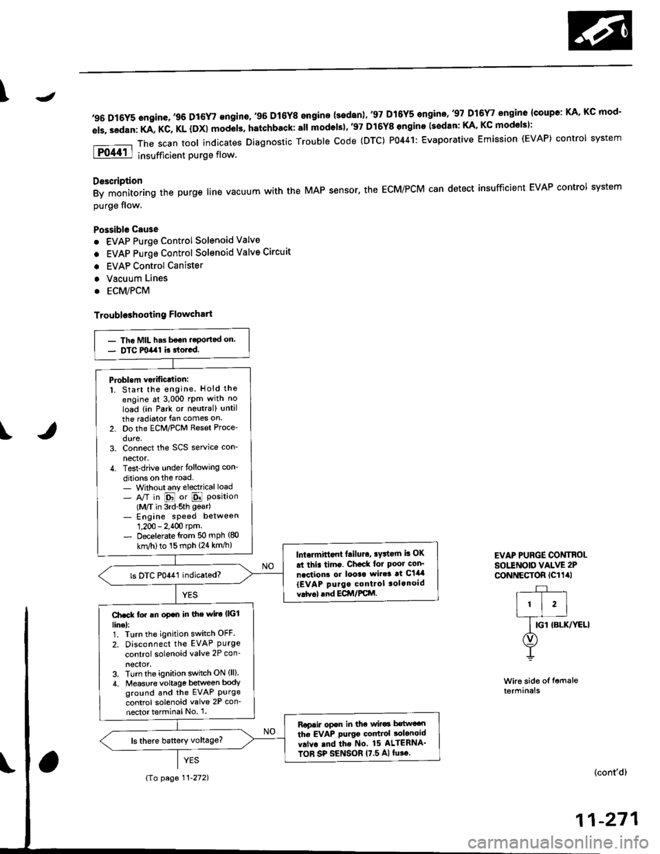
,96 D16Y5 engine,,96 D16r,gngino,,96 Dt6Y8 engine {3edan)' 37 D16Y5 engino..97 D16r, engine {coupe: KA, Kc mod-
els. sedan: KA, KC, KL {DX} models. hatchback: all modols}''97 Dl6Y8 ongine (s€dan: KA' KC mod€lsl:
The scan tool indicates Diagnostic Trouble code (DTC) P0441: Evaporative Emission (EVAP) control system
insufficient purge flow.
Description
By monitoring the purge line vacuum with the MAP sensor, the ECM/PCM can detect insufficient EVAP control system
purge flow.
Possible Cau3e
. EVAP Purge Control Solenoid Valve
. EVAP Purge Control Solenoid Valve Circuit
. EVAP Control Canister
. Vacuum Lines
. ECM/PCM
Troubl93hooting Flowchart
Wire side of femaleterminals
EVAP PURGE CONTROI-sottNotD vALvE 2P
CoNNECTOR (Cl1al
r-+-r
I'l'l
lG-ro.*l'rr"r
O)
Y
(cont'd)
11-271
- The MIL has bsGn.eportad on.- DTC milal k rtored.
Pioblem vsrificJtion:1. Start the engine. Hold the
engine at 3,000 rPm with no
load {in Park or noutral) until
the radiator fan comes on.
2. Do the ECM/PCM Reset Proce'
dure,3. Connect the SCS service con-
nector.4. Test-drive under following con-
ditions on the road- Without any electrical load- A/T in E or E Position(M/T in 3rd-sth gear)- Engine sPeed betweon
1,200 - 2.400 rpm.- Decelerate {rom 50 mph (80
knl/h)to 15 mph (24 km/h)lntormittont lailuro, sFtorn b OK
at thi. timo. Ch€ck tor Poor con'
ncction3 or looac wir.3 at C144
{EVAP purgo control tolonoid
vrtv.l .nd ECir/FCttl.
ls DTC P0441 indicatod?
Ch.ck fo. !n op€n in the wiro l|(illinel:1. Turn the ignition switch OFF.
2. Disconnect the EVAP Purgecontrol solenoid valve 2P con_
neclor,3. Turn the ignition switch ON (ll)
4. Measur€ voltage between bodyground and the EVAP Purgecontrol solenoid valve 2P con-
nector terminal No 1.
Rop.ir opor in tho wir6 b€two€n
the EVAP purgo codtiol tolonoid
v.lvo rnd tho No 15 ALIERNA'
TOR SP SENSOR 17.5 A)lu.o.
{To page 11-272)
Page 541 of 2189
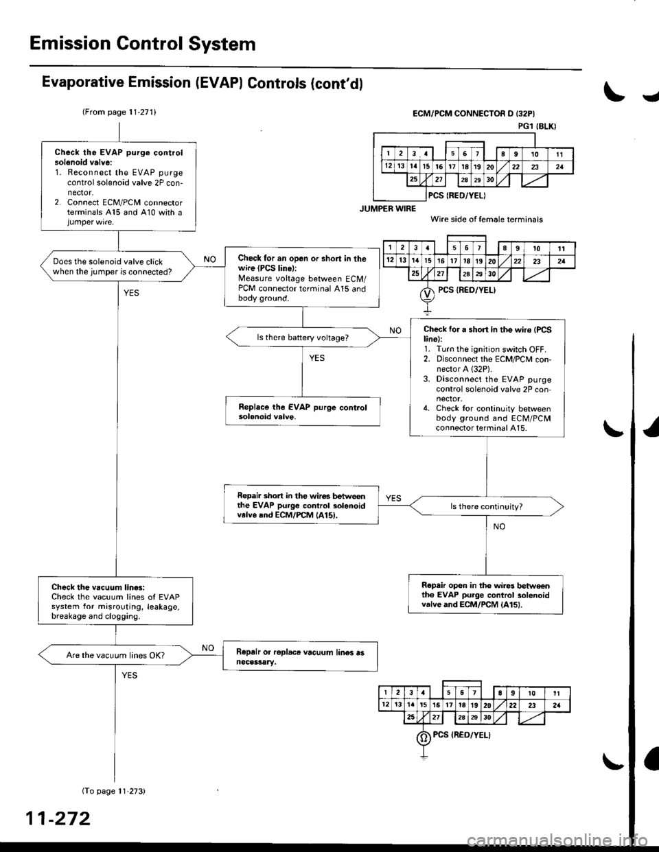
Emission Gontrol System
Evaporative Emission (EVAPI Controls (cont'dl
(From page 11-271)
I
ECM/PCM CONNECTOR D I32P}
PGl IBLKI
Check the EVAP purge controlsolenoid valvei1. Reconnect the EVAP purge
control solenoid valve 2P con-nector.2. Connect ECM/PCM connectorterminals A15 and 410 with a
Check for an open or short in thewire (PCS line):Measure voltage between ECM/PCM connector terminal A15 andbody gro!nd.
Does the solenoid valve clickwhen the jumper is connected?
Che'ck for a short in the wir6 {PCSline):1. Turn the ignition switch OFF.2. Disconnect the ECM/PCM con-nector A (32P).
3. Disconnect the EVAP purgecontrol solenoid valve 2P connector.4. Check lor continuity betweenbody ground and ECM/PCMconnector terminal A15.
Repai. short in the wir6s betwoonthe EVAP purge control solanoidvalve and ECM/rcM lA15l.
R€pair op€n in the wir$ betwo€ntho EVAP purge control solenoidvalve and ECM/rcM lA15l.
Check the vacuum lin€3:Check the vacuum lines ol EVAPsystem for misrouting, leakage,breakage and clogging.
Are the vacuum lines OK?
PCS {REO/YEL)
t389t0'tt
12l3'I'tt5t5'11IE1920232a
?5212A2930
PCS {RED/YEL)
23a67E9t0It
12t3'ta't5l617ta1920222321
2a2728A30
0) Pcs {REo/YELI
-272
Page 543 of 2189
Emission Control System
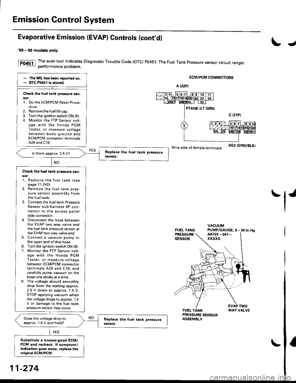
Evaporative Emission (EVAP) Gontrols (cont'd)
'99 - 0O models only:
The scan tool indicates Diagnostic Trouble Code (DTC) P0451: The Fuel Tank Pressure sensor circuit range/oerformance Droblem.
ECM/PCM CONNECTORS
wire side ot femare terminars sG2 IGRN/BLK)
FUEL TANKPRESSURESENSOR
VACUUMPUMP/GAUGE,0 - 30 in.Hg
FUEL TANKPRESSURE SENSORASSEMBLY
EVAP TWOWAY VALVE
IJ
tl'
Ths MIL has been reDortgd on.DTC m/$1 i3 stored.
Check the tuel tank pros3ure ser|-sor:1. Do the ECM/PCM Reset Proce-dure.2. Remove the tuellill cap.3. Turn the ignition switch ON (ll).4. N4onitor the FTP Sensor volt-age with the Honda PGMTester, or measure voltagebetween body ground andECN4/PCM connector terminalsA29 and C18.
ls there approx. 2.5 V7
Check tho tuel tank pressure !on-soa:1. Remove the fuel tank (seepage 11 2421.2. Remove the fuel tank pres-sure sensor assembly fromthe fueltank.3. Connect the fuel tank PressureSensor sub-harness 6P con-nector to the access panelside connector,4. Disconnect the hose betweenthe EVAP two way valvg andthe fuel tank pressure sensor atthe EVAP two way valve end.5. Connect a vacuum pump tothe open end ofthat hose.6. Turn the ignition switch ON (ll).7. Monitor the FTP Sensor volt,age with the Honda PGMTester, or measure voltagebetween ECM/PCM connectorterminals A29 and C18, andcarefully pump vacuum on thehose one stroke at a time.8. The voltage sho!ld smoothlydrop from the stading approx.2.5 V down to approx. '1.5 V.STOP applying vacuum whenthe voltage drops to approx. 1.5V or damage to the fuel tankpressure sensor may occur.
Does the voltage drop toapprox. 1.5 V and hold?
Sub3titute a known-good ECM/PCM and r6check. It symptom/indicltion 90e3 aw.y, replac\. th€original ECM/PCM.
A (32P)
A973X - 041 -
xxxxx
11-274
Page 544 of 2189
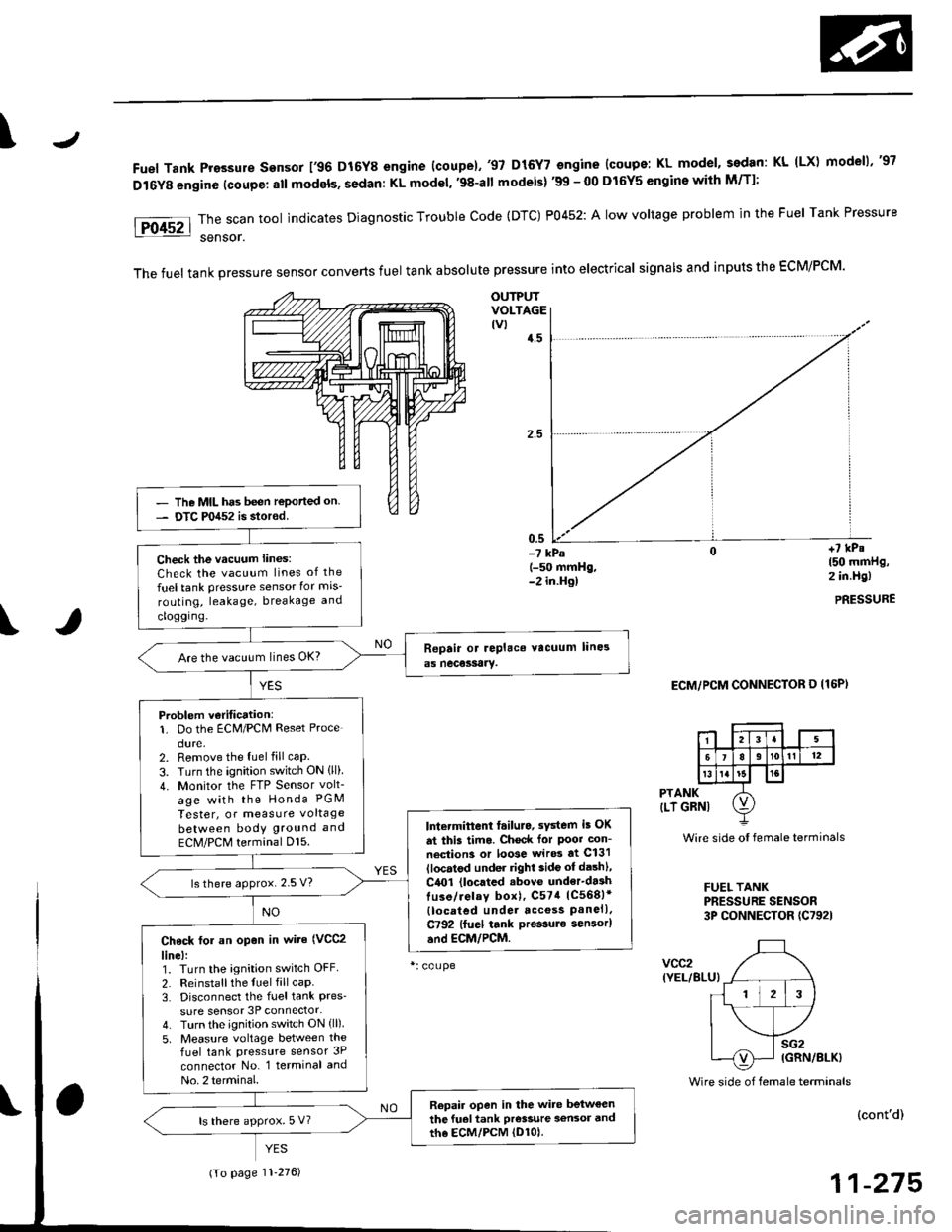
\J
Fuel Tank Pro3sure sensor 196 D16Y8 engine (coupe).'97 D15Y7 engine {coupe: KL model, sedan: KL (LX) modeu,'97
D16Y8 engine (coupe: all models, sedan: KL model, '98-all models) '99 - 00 D16Y5 engine with M/Tl:
\
PTANK
{LT GRNI
vcc2(YEL/BLU}
Wire side oI female terminals
FUEL TANKPRESSURE SENSOR3P CONNECTOR (C7921
sG2IGRN/8LK)
Foc2l::il":"toolindicatesDiagnosticTroublecode(DTc)P0452:A|owvo|tageprob|emintheFue|TankPressure
The fuel tank pressure sensor converts fuel tank absolute pressure into electrical signals and inputs the EcM/PCM.
OUTPUTVOLTAGEtvt4.5
-? kPa(-50 mmHg,-2 in.Hg)
ECM/PCM CONNECTOR O I16P)
Wire side of female terminals
+7 kPs150 mmHg,2 in.Hg)
PRESSURE
(cont'd)
11-275
- The MIL has been reported on- DTC P0452 is stored.
Check the vacuum lines:
Check the vacuum lines of the
fuel tank pressure sensor for mis-
routing, leakage, breakage and
cloggrng.
Are the vacuum lines OK?
Problem v€ritication:1. Do the ECM/PCM Reset Proce
dure.2. Remove the luel fill caP.
3. Turn the ignition switch ON lll)4. Monitor the FTP Sensor volt_
age with the Honda PGM
Tester, or measure voltage
between bodY ground and
ECM/PCM terminal Dl5.lntermittent tailuro, sYstem i5 OK
dt this timo. Chock for Poot con-
neciion3 or loose wir* at C131
llocatod under right side ot dashl,
C4O1 (located .bove under'da3htuso/ielay box), C574 1C568)*
{located under acc€ss Panell.C792 lfuel tank pressule sen3or)
and EcM/PCM.
ls there approx. 2.5 V?
Check tol an op€n in wite (VCC2
line):1. Turn the ignition switch OFF
2. Reinstallthe fuel fill caP.3. Disconnect the fuel tank Pres'sure sensor 3P connector-4. Turn the ignition switch ON (ll)
5, Measure voltage between the
fuel tank pressure sensor 3P
connector No. l terminal and
No. 2 terminal.
Repair open in the wite betweenthe fuel tank Pr€s3ure a€n3or andth6 EcM/PcM (D1ol.ls there approx. 5 V?
(To page 11'276)
Page 545 of 2189
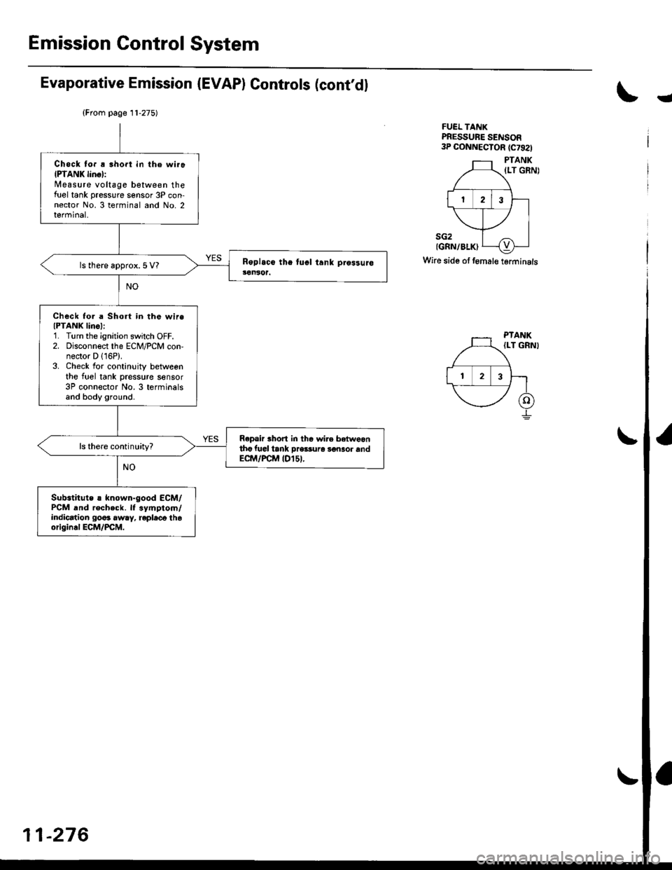
Emission Control System
Evaporative Emission (EVAP) Controls (cont'dl
!
FUEL TANKPRESSURE SENSOR3P CONNECTOR {C7921
PTANK
{LT GRN)
sG2{GRN/BLK)
Wire side of f€mal€ terminals
{From page 11-275)
Check to. ! short in the wiroIPTANK linol:Measure voltage between thefirel tank pressure sensor 3P con-nector No. 3 terminal and No. 2terminal,
ls there approx.5 V?
Check fo. a Short in the wireIPTANK IinoI:1. Turn the ignition switch OFF.2. Disconnect the ECM/PCM con,nector D 116P).3. Check for continuity betweenthe fuel tank pressure sensor3P connector No.3 terminalsand body ground.
Repair thort in thc wire betweantho fuel iank pre$uro 3€naor andECM/FCM tDl5t.
ls there continuity?
Substitute ! known-good ECM/PCM and recheck. lf .ymptom/indication go6s awry, repleco th6origin.l ECM/PCM.
PTANK{LT GRNI
-276
Page 547 of 2189
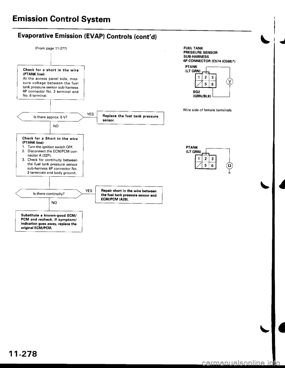
Emission Control System
Evaporative Emission (EVAPI Controls {cont,dlJ
FUEL TANKPRESSURE SENSORSU8-HABNESS6P CONNECTOR 1C574 tC568)rt
PTANK
{LT GRN}
PTANK
ILT GRN}
Wire side of female terminals
(From page 11-277)
Check for a short in the wire{PTANK line):At the access panel side, measure voltage between the fueltank pressure sensor sub-harness6P connector No. 2 terminal andNo. 6 terminal.
ls there approx. 5 V?
Chock lor a Short in the wi.e(PTANK line):1. Turn the ignition switch OFF.2. Disconnect the ECM/PCM con-nector A (32P).
3. Check for continuity betweenthe fuel tank pressure sensorsub-harness 6P connector No.2 terminals and body ground.
Repair short in the wi.e betwsenthe luel tank pressure sensor andECM/PCM {A291.
Subsiitute a known-good ECM/PCM and rechock. lf symptom/indication goes away, replac€ theoriginal ECM/PCM.
11-278
Page 549 of 2189
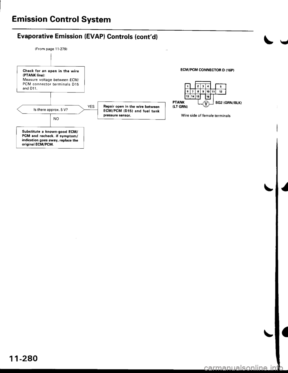
Emission Control System
Evaporative Emission (EVAPI Controls (cont'dl
\v
ECM/PCM CONNECTOR D {16PI
PTANK
{LT GRN)SG2 (GRN/BLK}
Wire side of female terminals
lFrom page 11-2791
Check for an open in the wire{PTANK line):Measure voltage between ECM/PCM connector terminals D15and D]1.
Repair open in the wire betweenECM/PCM lD15) and luel tankpressuae sensor.
ls there approx. 5 V?
Substitute a known'good ECM/PCM end recheck. lt symptom/indication goes awav, replace theoriginal ECM/PCM.
-2AO