mat HONDA CIVIC 1999 6.G Workshop Manual
[x] Cancel search | Manufacturer: HONDA, Model Year: 1999, Model line: CIVIC, Model: HONDA CIVIC 1999 6.GPages: 2189, PDF Size: 69.39 MB
Page 1825 of 2189
How To Use This Manual
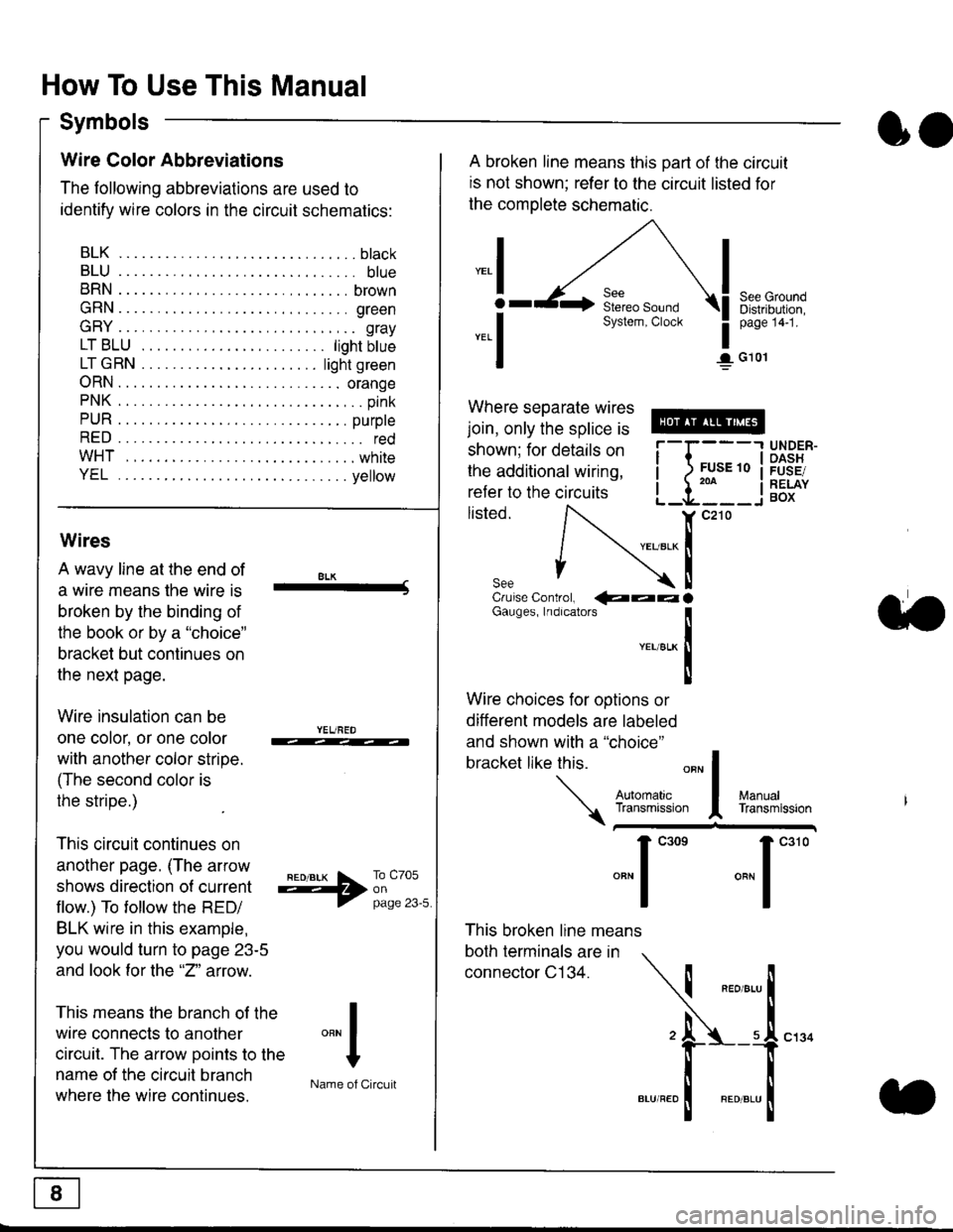
Symbols
oo
Wire Color Abbreviations
The following abbreviations are used to
identify wire colors in the circuit schematics:
BLK.... .........b|ack
BLU.... ......... blue
BRN.... ,....... brown
GRN.... ........ green
GRY.... ......,.. gray
LTBLU . .....lightbtue
LTGRN. ....lightgreen
ORN.... ....... orange
PNK .... .......,.. pink
PUR .... ........ purple
RED .... .......... red
WHT... .........white
YEL .... ........ yellow
A broken line means this part of the circuit
is not shown; refer to the circuit listed for
the complete schematic.
"ral
o
-.1
See GroundDistribution,page 141.
I G101
Where separate wires
join, only the splice is
shown; for details on
the additional wiring,
refer to the circuits
listed.ili::i
{[
UNDER-OASHFUSE/RELAYBOX
Wires
A wavy line at the end of
a wire means lhe wire is
broken by the binding of
the book or by a "choice"
bracket but continues on
the next page.
Wire insulation can be
one color, or one color
with another color stripe.
(The second color is
the stripe.)
This circuit continues on
another page. (The arrow
shows direction o{ current
flow.) To tollow the RED/
BLK wire in this example,
you would turn to page 23-5
and look for the "2" anow.
This means the branch of the
wire connects to another
circuit. The arrow Doints to the
name of the circuit branch
where the wire continues.
8LK-Cruise Control, €�aaaGauges, Indrcalors
!YEUsLK
Ttl
Wire choices for options or
different models are labeled
and shown with a "choice"
bracket like this.
This broken line means
both terminals are in
connector C134.
a.
+##l:i""lManuallransmission
ryil;::,
.""1
""'
"""1".'0
I
""^l
:-lName of Circuit
Page 1826 of 2189
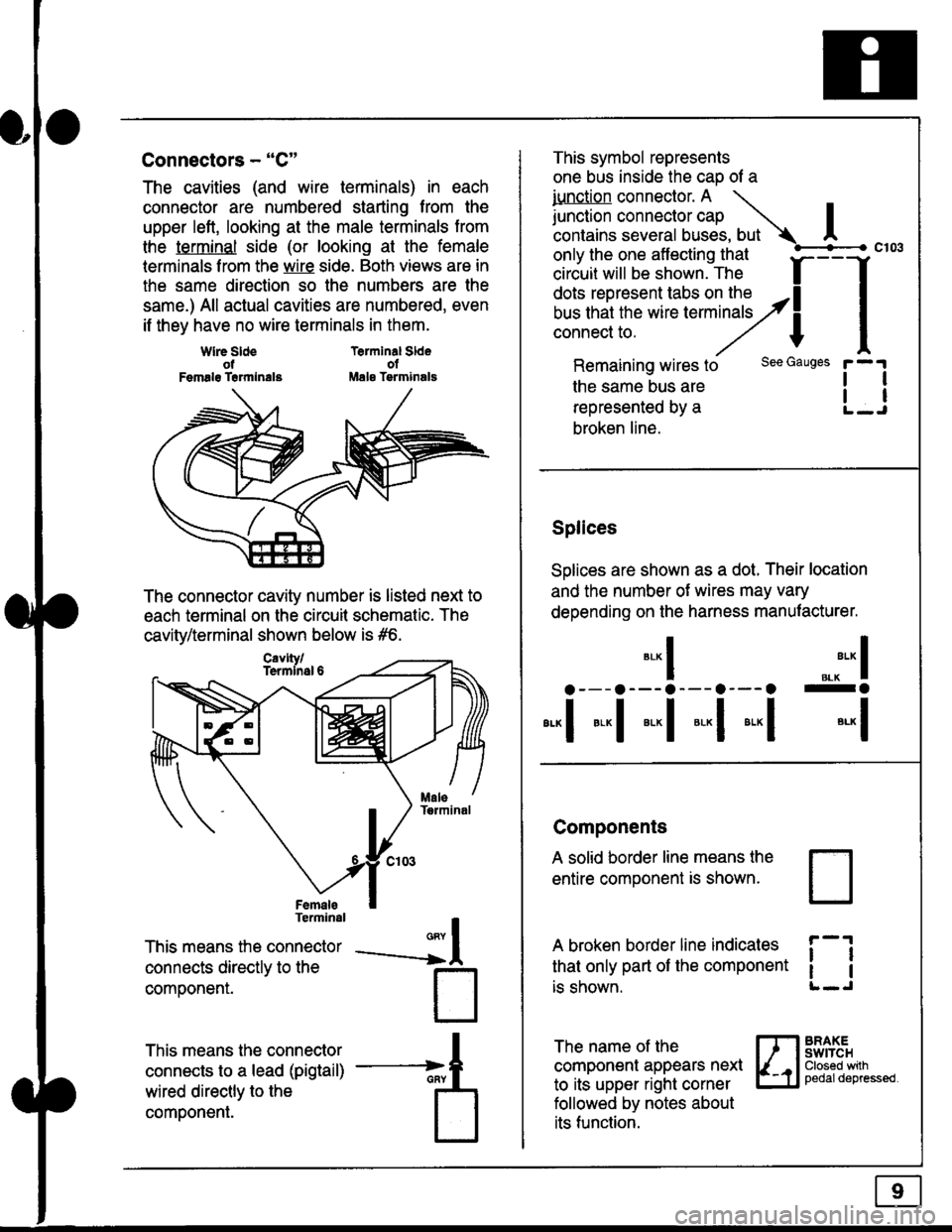
Connectors - "C"
The cavities (and wire terminals) in each
connector are numbered starting from the
upper left, looking at the male terminals trom
the terminal side (or looking at the female
lerminals f rom the wire side. Both views are in
the same direction so the numbers are the
same.) All actual cavities are numbered, even
if they have no wire terminals in them.
Terminal SldeolMale Tsrminals
{
T
_A
Wlre SldeotFemalg Trrmlnala
The connector cavity number is listed next to
each terminal on the circuit schematic. The
cavity/terminal shown below is #6.
Terminal
This means the connector
connects directly to the
componenr.
This means the connector
connects to a lead (pigtail)
wired directly to the
component.
Cavlty/Termlnsl 6
only the one affecting that
ciriuit will be shown. The f
--f
!!*!"*F"#fi5'�;,Hy4
I
Remaining wires to
the same bus are
represented by a
broken line.
The name of the
component appears next
to its upper right corner
followed by notes about
its function.
This symbol represents
one bus inside the cao of a
iunction connector. A \
lr"ctb. connectorcap |contains several buses, but Ac103
tl
tl
*-
I ",.-"* I
a---a---a--- a--- o -a
*"1 *-l *-l *-l *"1 *-l
See Gauges
Splices
Solices are shown as a dot. Their location
and the number of wires may vary
depending on the harness manufacturer.
Components
A solid border line means the
entire component is shown.
A broken border line indicales
that only part of the component
is shown.
t_J
ll
ll
BRAXEswtTcHClosed wilhpedaldepressed.
Page 1828 of 2189
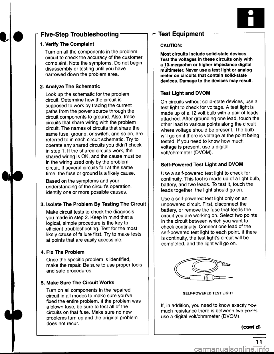
Five-Step Troubleshooting
L Verify The Complaint
Turn on all the components in the problem
circuil lo check the accuracy of the customer
complaint. Note the symptoms. Do not begin
disassembly or testing until you have
narrowed down the problem area.
2. Analyze The Schematic
Look up the schematic for the problem
circuit. Determine how the circuit is
supposed to work by tracing the current
paths lrom the power source through the
circuit components to ground. Also, trace
circuits that share wiring with the problem
circuit. The names of circuits that share the
same fuse, ground, or switch, and so on, are
referred to in each circuit schematic. Try to
operate any shared circuits you didn't check
in step 1 . lt the shared circuits work, the
shared wiring is OK, and the cause must be
in the wiring used only by the problem
circuit. lf several circuits fail at the same
time, the fuse or ground is a likely cause.
Based on the symptoms and your
understanding of the circuit's operation,
identify one or more possible causes.
3. lsolate The Problem By Testing The Circuit
Make circuit tests to check the diagnosis
you made in step 2. Keep in mind that a
logical, simple procedure is the key to
efficient troubleshooting. Test for the most
likely cause of failure first. Try to make tests
at points that are easily accessible.
4. Fix The Problem
Once the specific problem is identified,
make the repair. Be sure to use proper tools
and safe procedures.
5. Make Sure The Circuit Works
Turn on all components in the repaired
circuit in all modes to make sure you've
fixed the entire problem. ll the problem was
a blown fuse, be sure to test all of the
circuits on that fuse. Make sure no new
problems turn up and the original problem
does not recur.
Test Equipment
Most circuits include solid-state devices.
Test the voltages in these circuits only with
a 1o-megaohm or higher impedance digital
mUltimeter. Never use a test light or analog
meter on circuits that contain solid-state
devices. Damage to the devices may result.
Test Light and DVOM
On circuits without solid-state devices, use a
test light to check for voltage. A test light is
made up of a 12 volt bulb with a pair of leads
attached. After grounding one lead, touch the
other lead to various points along the circuit
where voltage should be present. The bulb
will go on if there is voltage at the point being
tested. lf you need to know how much
voltage is present, use a digital
volVohmmeter (DVOM).
Self-Powered Test Light and DVOM
Use a self-powered test light to check for
continuity. This tool is made up of a light bulb,
battery, and tlvo leads. To test it, touch the
leads together: the light should go on.
Use a self-powered test light only on an
unoowered circuit. First, disconnect the
battery, or remove the fuse that feeds the
circuit you are working on. Select two points
in the circuit belween which you want to
check continuity. Connecl one lead of the
self-powered test light to each point. lf there
is continuity, the test light's circuit will be
completed, and the light will go on.
SELF-POWERED TEST LIGHT
lf, in addition, you need lo know exacW hc'.
much resistance there is between two oo'^=
use a digital volUohmmeter (DVOM)
acdrt'Cn
t1
Page 1831 of 2189
How To Use This Manual
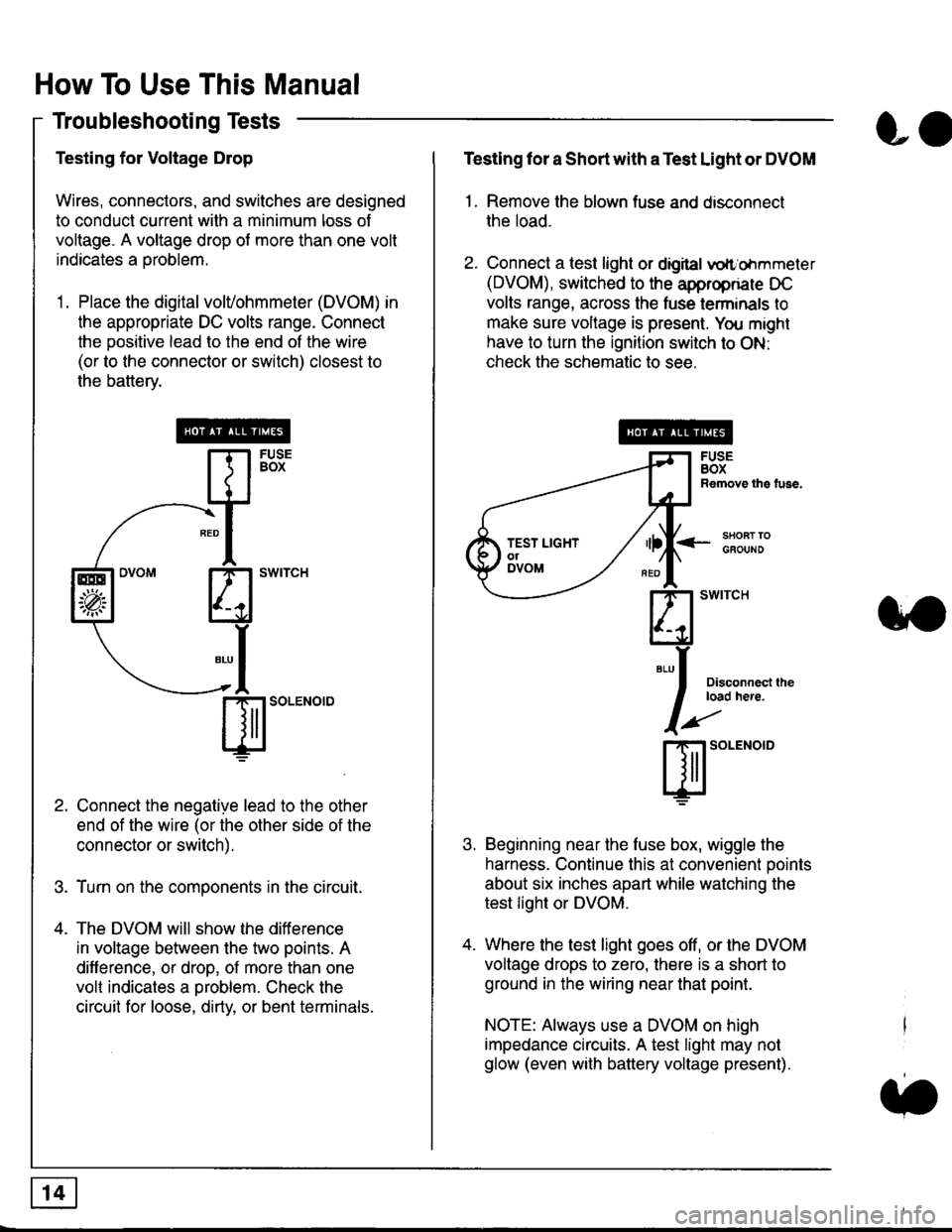
Troubleshooting Tests
Testing for Voltage Drop
Wires, connectors, and switches are designed
to conduct current wilh a minimum loss of
voltage. A voltage drop of more than one volt
indicates a Droblem.
'1. Place the digital volVohmmeter (DVOM) in
the appropriate DC volts range. Connect
the positive lead to the end of the wire
(or to the connector or switch) closest to
the bafterv.
Connect the negative lead to the other
end of the wire (or the other side of the
connector or switch).
Turn on the components in the circuit.
The DVOM will show the difference
in voltage between the two points. A
difference, or drop, of more than one
volt indicates a oroblem. Check the
circuit for loose, dirty, or bent terminals.
co
Testing lor a Short with a Test Light or DVOM
1. Remove the blown fuse and disconnect
the load.
2. Connect a test light or digital
oltr'ohmmeter
(DVOM), switched to the appropnare DC
volts range, across the tuse lerminals to
make sure voltage is present. You might
have to turn the ignition switch to ON:
check the schematic to see.
<-s80RT TOGFOUNO
Disconnecl lheload here.
Beginning near the luse box, wiggle the
harness. Continue this at convenient ooints
about six inches apart while watching the
test light or DVOM.
Where the test light goes off, or the DVOM
voltage drops to zero, there is a short to
ground in the wiring near that point.
NOTE: Always use a DVOM on high
impedance circuits. A test light may not
glow (even with battery voltage present).
3'�'
ffito.'"o'o
.t.
TEST LIGHTolDVOM
Page 1834 of 2189
![HONDA CIVIC 1999 6.G Workshop Manual Fuse/Relay Information
- Under-dash Fuse/Relay Box
Front View
c712(To moonroof wire harness)
. : Canadai : Not UsedO : C926 loprion (+B)l
@ : C927 loption (dash lights)]
O : C928 [Option (ACC]I
@ : C9 HONDA CIVIC 1999 6.G Workshop Manual Fuse/Relay Information
- Under-dash Fuse/Relay Box
Front View
c712(To moonroof wire harness)
. : Canadai : Not UsedO : C926 loprion (+B)l
@ : C927 loption (dash lights)]
O : C928 [Option (ACC]I
@ : C9](/img/13/6068/w960_6068-1833.png)
Fuse/Relay Information
- Under-dash Fuse/Relay Box
Front View
c712(To moonroof wire harness)
. : Canadai : Not UsedO : C926 loprion (+B)l
@ : C927 loption (dash lights)]
O : C928 [Option (ACC]I
@ : C929 loption (lc2)l
Rear View
css2
c421(To main wire harness)
c801CI-o SRS main harness)
c501(To dashboard wire harness)
^ : Not used ('96-'97 models)
c913(To ignition switch)
INTEGRATEDCONTROL UNITCONNECTOR A
c419Oo main wire harness)
REAR WINDOWDEFOGGER RELAY
TURN SIGNAUHAZARD RELAY
c423(To main wire harness)
co
c422(To main wire harness)
POWERwtNDowRELAY
c551flo lloor wire harness)c439 f96.'97 MODELSand ALL GX MOOELS)(To main wire harness)
T1 T-t T"l T"t r-r r-'l T1 F n r-l r-l r'123 24 25 26 27 28 29 30 31 32 33I-J I.J I.J IJ IJ IJ LJ IJ IJ I.J I.J I-I
r"1 r-t r-t T-l r"l r-r Fl r:1 n rJ n -12 13 14 t5 16 17 t8 19 2A 2t 22LI I.J L! LI tJ LJ (J LI IJ IJ T-I I.J
n r:l rj.l |-l T"l Tl r:t n r-l |;.l r-r r-l1 2 3 4 5 6 7 I 9 10 11LI LI IJ LJ LJ I,J T-I I.J TJ IJ I.-I tJ
c420(To main wire harness)
6
(To floor wire harness)
Page 1836 of 2189
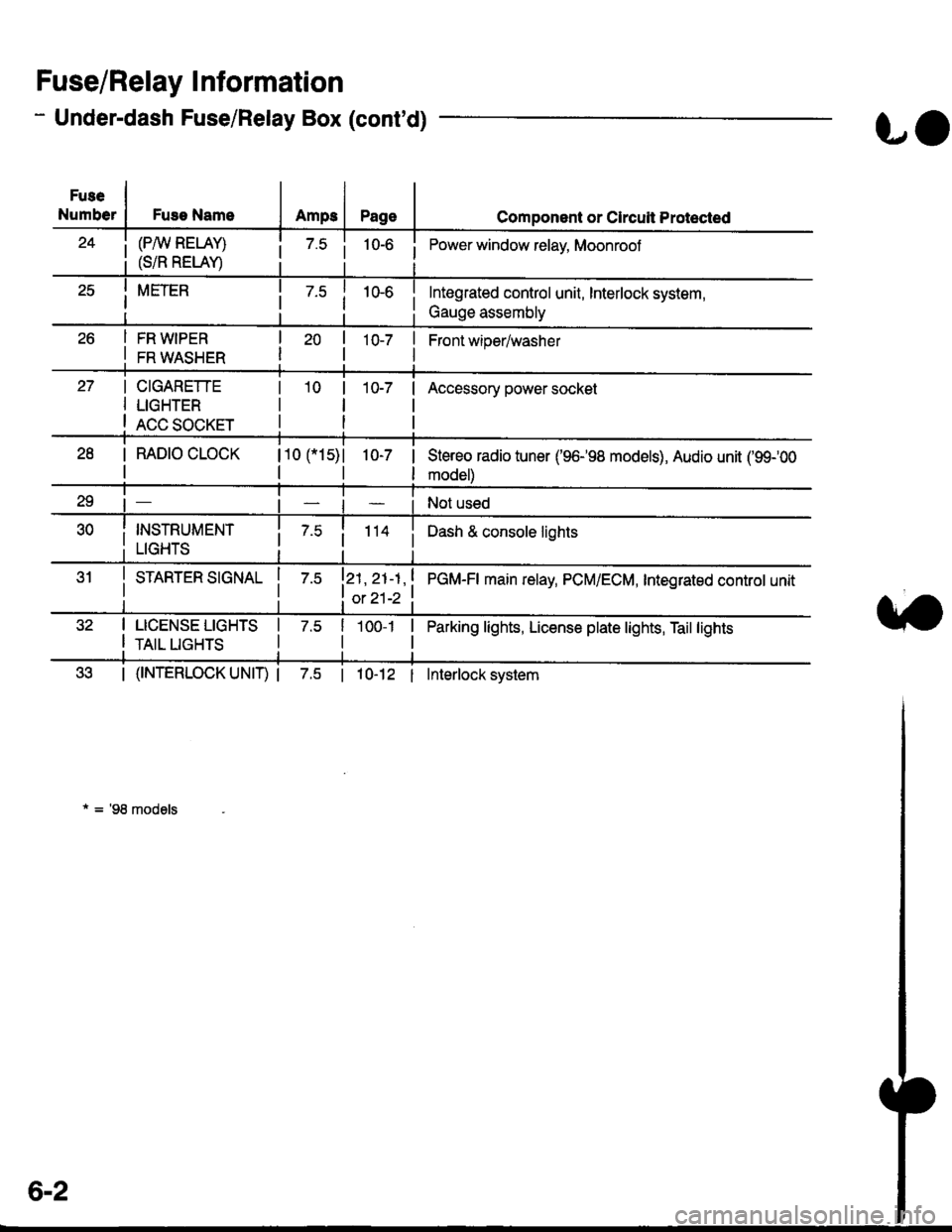
- Under-dash Fuse/Relay Box (cont'd)
Fuse/Relay I nformation
Fuse
NumberFuse NameAmps
(P/W RELAY)
(S/R RELAY)
FR WIPER
FR WASHER
LO
Page
10-7 |
I
Component or Clrcuit Protected
i Power window relay, Moonrool
Front wioer/washer
CIGARETTE
LIGHTER
ACC SOCKET
10-7Accessory power socket
I RAD|O CLOCK
I
110 115)l
tl
1O-7 |
I
Stereo radio tuner ('96198 models), Audio unit ('99100
model)
Not used
i 7.5i 114 iDash & console lights
I srnnrensrorunl | 7.slzl , zt -t , ! eCU-n main retay, PCM/ECM, Integrated controt unit
I ot 21-2 t
I LICENSE LIGHTS I 7.5
I rerr uesls I
Parking lights, License plate lights, Tail lights| 1oo-1 |
tl
| (f NTERLOCK UNIT) | 7.5 | 10-12 I Interlock system
* = '98 models
6-2
Page 1838 of 2189
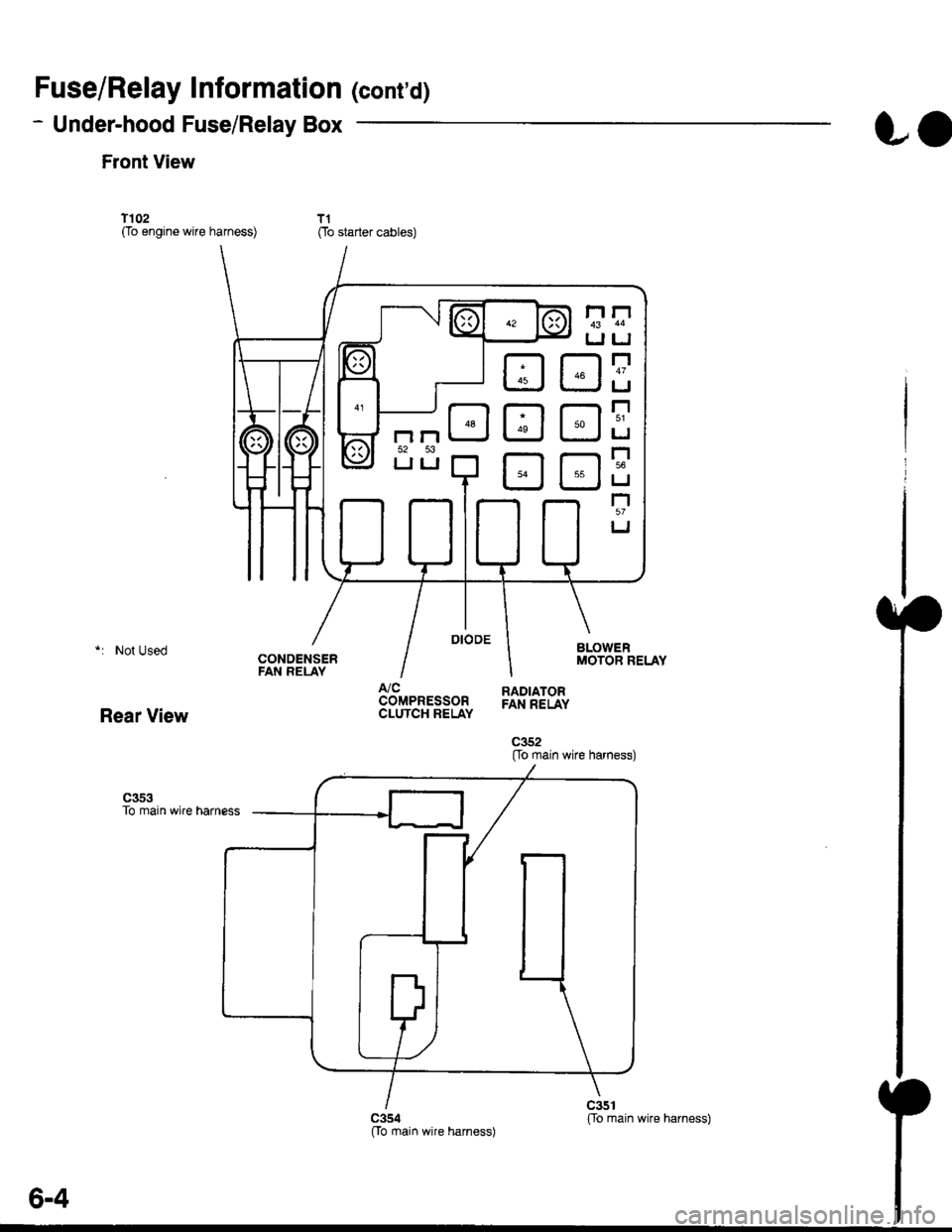
Fuse/Relay Information lcont'd)
- Under-hood Fuse/Relay Box
Front View
T'102(To engine wire harness)
LO
T1Oo starter cables)
*: Not Used
Rear View
c353To main wire harness
DE
tr
tr
tr
t-l
IJ
n
tJ
t-l51
IJ
n
IJ
n5T
IJ
[[o main wire harness)
6-4
ffo main wire harness)fto main wire harness)
Page 1858 of 2189
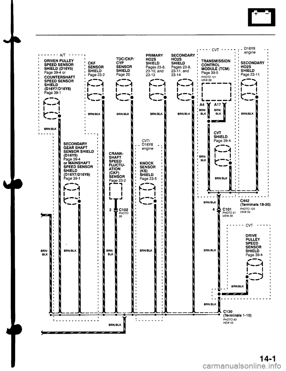
----" A/T -----t
DRIVEN PULLEY , ^.,.
;iftTBilis'".f l5Ftr,.""_
co'rinienixnn '. Pase 23'2
SPEED SENSOR ; .'-\.SHIELD 'F--.1
TDC/CKP/CYPSENSORSHIELDPage 20
ll
r_:.-i
23-13
t1
23- l4
tl
PRIMARY SECONDARYHO2S HO2SSHIELD SHIELDPages 23-8, Pages 23-9,23-10. and 23-11. and
--- CW ----.
TRANSMISSION ;CONTROLMODULE(TCM) ,Page 39-5 :PHO|O 121vlEw 69r____1 ,
tt:
tt:L----J,
. D16Y8engine
SECONDARY .
HO2S :SHIELD ;Page 23-11
l. - -..1 ;
tt:(D16Y/i D15Y8)Page 39-1
l.--.1
1l
r:--iBFN/BLKARN/BLK
A4
6FN/BLK' EFN/BI
i i srco"oo"t :' I GEAR SHAFT
I I Or MAtN!'tAt I. II SPEED SENSOR '
CW. - D16Y8 -, engine: N SENSoR SHTELD ,
i !i?il3li*u,, i
CWSHIELD :Page39-4,
CRANK-SHAFTSPEEDFLUCTU-ATION(cKF)SENSORPage 23-2
tl
ll
;I;..
26
i xNocx' SENSOR, (KS)' SHIELD
, Fage zJ-5
: F--.1
:ll
iilr-:i
----:.--------:
c442(Terminals 18-20)
c10.1 PHofo 125\HOTO 21 VIEW 54vtEw 29
'----- cw ----'
DRIVE
BFN/BLK
PULLEY :SPEEDSENSORSHIELDPage 39-4 :
1.---{ :I t;
cl30Oermlnal8'l-10)
vtEw 52
14-'�,
Page 1875 of 2189
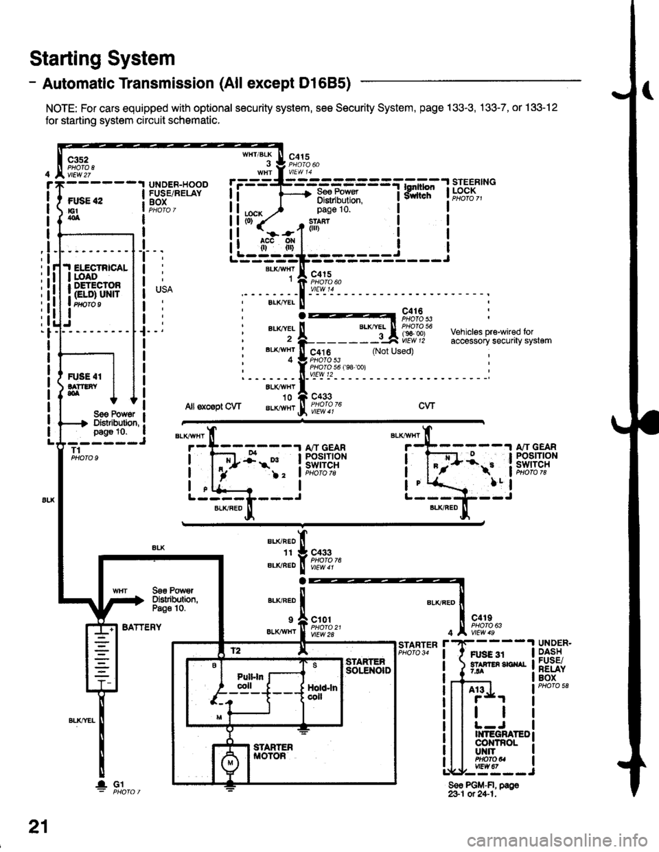
- Automatic Transmission (All except Dl685)
NOTE: For cars equipped with optional security system, see Security System, page 133-3, .133-7, or 133-12
for starting system circuit schomatic.
Starting System
c3s2PHO|O IvlEw 27
ftxiE "2E1404
WHT/BLK
I
lta":
c415
=-mF,Uf.
--l
9,lLT i ld;f,,"-
I
I
It
I
I
I
I
I
I
I
I
pag€ 10.
slan?(ll)
c415
I
Ji.I ELECTRICALI roAoI DETECTOR
I Gt ol ulra Ptfifo I
IJ
BLKAIVHT1
ELK./YEL
au(|vEL
BL'(4I/HT
4
c416PHOTO 53
c4t 6PHO|O 53PHO|O 56 f98 '�oo)vtEw t2
c433
Vehiclss pre-wired foraccessory securaty system(Not Used)
R'SE 4IlA??tNY,olALXAVHY'10
Allsxcsptow aLKlvHrcwSoe Pow6r IDistibution, !page 10. a- ----JT1PHOTO 9
BATTERY
BLKAVHT
7
L-----L---JBLKFED
13:;-1ifl;ft?R
!-
)2 'lPHoto tg
a
BLI(RED
1I
ELIVBED
ALKNED
c433PHOTO 76
Soe PowrDslributbn,Pa€o 10.
9 a c101
er.xiwxr I ffo,rtfl'�t
c4rIPHO|O 63
Ft gg 3r5? F En 3E ^r7.94
4
r'STARTERPHO|O 34UNDER.DASHFUSE/RELAYBOX
A13
tl
II{TEGRATEDco|{TnoLUT{ITPHOfOUvtEw 67,--==--J
Sso PGM-FI, page&1 ot 24-1.
21
lGl
Page 1876 of 2189
![HONDA CIVIC 1999 6.G Workshop Manual - Automatic Transmission (D1685)
c352
vtEw27
FUSE 42tGtao
.I ELECTRICALI LOADr DETECIOn
| (ELD) uNtrI PHOTO 9
I
UNDER.HOOOFUSE/RELAYBOX
r=-----L-_-_-_-_-_-=_-_-Tl.*1"","1#"Ei]""
li F 3,"j,[,ul
WHT/BL HONDA CIVIC 1999 6.G Workshop Manual - Automatic Transmission (D1685)
c352
vtEw27
FUSE 42tGtao
.I ELECTRICALI LOADr DETECIOn
| (ELD) uNtrI PHOTO 9
I
UNDER.HOOOFUSE/RELAYBOX
r=-----L-_-_-_-_-_-=_-_-Tl.*1"","1#"Ei]""
li F 3,"j,[,ul
WHT/BL](/img/13/6068/w960_6068-1875.png)
- Automatic Transmission (D1685)
c352
vtEw27
FUSE 42tGtao
.I ELECTRICALI LOADr DETECIOn
| (ELD) uNtrI PHOTO 9
I
UNDER.HOOOFUSE/RELAYBOX
r=-----L-_-_-_-_-_-=_-_-Tl.*1"","1#"Ei]""
li F 3,"j,[',ul
WHT/BLK
. J 9,1'3.WHt a V|EW 14
tcx,^ ) Page 10'
PHOTO 76
1--*---''!N"t- \o3bz7
See PowerDistribution,page 10.
c433
ALKRED4
r-^==.1
Stadorcontrol
POWERTRAINCONTROLMODULE (PCM)
c101
vtEw 28
ll
"'{----1iLi.' | |
Li-gl{l======i---i
"i*-iIr-m'
:il
See PowerDistribdion,Page '10.
".u,"if---'
-,*! s#;:{"
BLKAVHT N V/EW a t
STARTERCUTFELAYPHO|O 129
(99100)
A"/T GEARPOStTtONswrTcH
See PGlr-Fl,page 25.
STARTER
c419
FUSE 31STAffER Src{AI7.54
UNDER-DASHFUSE/NELAYBOX
BLKREO
11
"'-";;tr
A't 3
BATTERY
21-1