Lift HONDA CIVIC 1999 6.G Owner's Manual
[x] Cancel search | Manufacturer: HONDA, Model Year: 1999, Model line: CIVIC, Model: HONDA CIVIC 1999 6.GPages: 2189, PDF Size: 69.39 MB
Page 378 of 2189
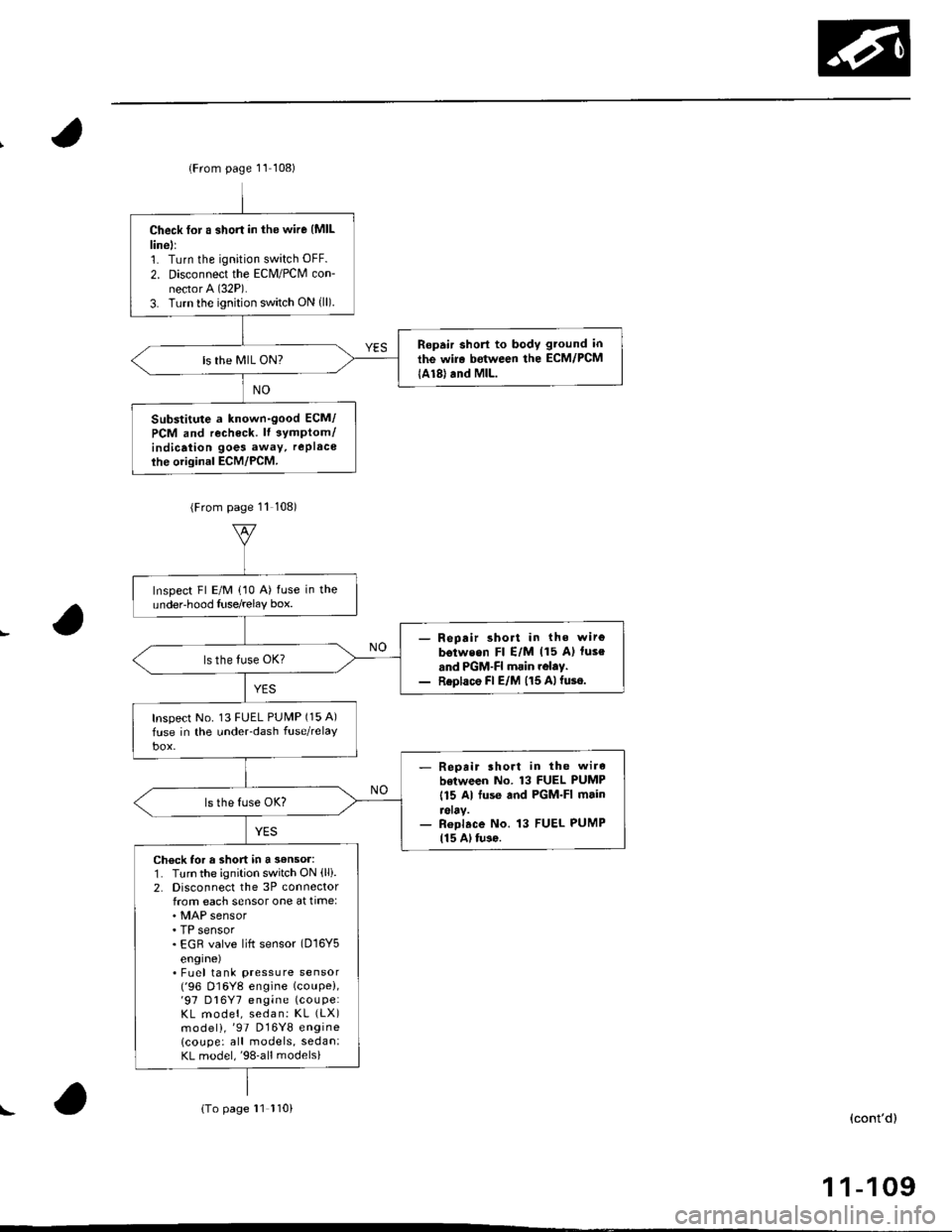
lFrom page 11 108)
Check for a short in the wire {MlLlinell1. Turn the ignition switch OFF.
2. Disconnect the Eclvl/PCM con-nector A (32P).
3. Turn the ignition switch ON {ll).
Ropair short to body gtound in
the wir. between the ECM/PCM
lA18) and MlL.ls the MIL ON?
Substitute a known-good ECM/
PCM and recheck. lt 3ymptom/indicaiion goes away, rePlace
ihe original ECM/PCM.
(From page 11 108)
Inspect Fl E/M (10 A) fuse in theundeFhood Iuse/relay box.
- Repair short in the wirg
b€tweon Fl E/M (15 A) luse
and PGM-FI main rolay.- Replace Fl E/M (15 Alfuse.
Inspect No. 13 FUEL PUMP (15 A)
fuse in the under-dash fuse/relaY
- Repait lhort in the wire
botween No. 13 FUEL PUMP
115 Al fuse and PGM-FI main
reray.- Roplace No. 13 FUEL PUMP115 Al tu3o.
Check for a short in a 3€nsor:1. Turn the ignition switch ON (lli.
2. Disconnecl the 3P connectorfrom each sensor one at time:
. TP sensor. EGR valve lift sensor (D16Y5
engrne). Fuel tank pressure sensor('96 D16Y8 engine (coupe),'97 D16Y7 engine (couPe:
KL model, sedan: KL (LX)
model),'97 D16Y8 engine
lcoupe: all models, sedan:KL model,'98-all models)
{To page 11 110)(cont'd)
1 1-109
!
Page 379 of 2189
PGM-FI System
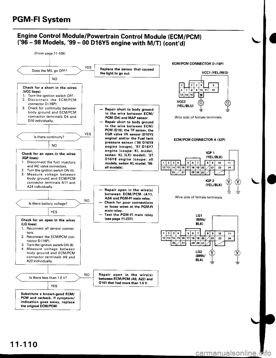
(From page 11-109)
Replace the sensor that causedthe light to go out.Does the N4lL go OFF?
Check fo. a short in the wi.os(VCC lines):':. Turn the ignition switch OFF.2. Disco n n ect the ECM/PCMconnector D (16P).
3. Check for continuity betweenbody ground and ECM/PCMconnector terminals D4 andD10 individually.
Ropair short to body groundin the wire betweon ECM/PCM {O4) and MAP s6n3or.Repair short to body groundin the wire between ECM/PCM lD10l, the TP sensor, theEGR valve lift sensor {D16Y5engine) and/or the Fuel tankpressure sensor {'96 Dl6Ygengine lcoupe),'97 D16Y7engine (coupe: KL model,sedan: KL (LXl model), '97
D16Y8 engine (coupe: allmodels, sedan: KL model. €8-allmodelsl.
ls there continuity?
Check tor rn open in the wires(lGP lines):1. Disconnect the fuel injectorsand IAC valve connectors,2. Turn the ignition switch ON (ll).3. Meas u re voltage betweenbody ground and ECM/PCMconnector terminals A11 and424 indivjdually.- Repair open in the wirels)between ECM/PCM (A11,A24land PGM-Fl main relay.- Check for poor connectionsor loose wiras at the PGM-FImain relay,- Test the PGM-FI mdin relavlsee pag6 11-237).
ls there battery vohage?
Check for an open in the wires(LG line3):1. Reconnect all sensor connectors.2. Reconnect the ECM/PCM con-nector D (16P).
3. Turn the ignition switch ON (ll).4. Measure vo ltage betweenbody ground and ECM/PCMconnector terminals Ag andA22 individually.
Repair open in the wirolglb€twe€n ECM/PCM {A9, A22} andG101 that had more than 1.0 V.
ls there less than 1.0 V?
Substitute 6 known-good ECM/PCM and r€check. lf symptom/indication 9o€s away, replacethe original ECM/PCM.
Engine Control Module/Powertrain Control Module (ECM/pCMl
('96 - 98 Models, '99 - 00 D16Y5 engine with M/Tl (cont,dl
ECM/PCM CONNECTOR D {16P}
Wire side of female terminals
ECM/PCM CONNECTOR A (32P}
Wire side of female terminals
11-110
LG1
VCCl {YEL/RED}
IGP 1{YEL/BLKI
2I11
1213l5t6Itt8t9202321
25272a2930
IGP 2(YEL/BLKIv) (l
{8RN/BLK)
I258tol1'12tt11t5l617t8t920232a
2A2330
LG2{8RN/8LK}
Page 380 of 2189
Engine Control Module/Powertrain Control Module (ECM/PCM)
('95 - 00 Models except Dl6Y5 engine with M/T)
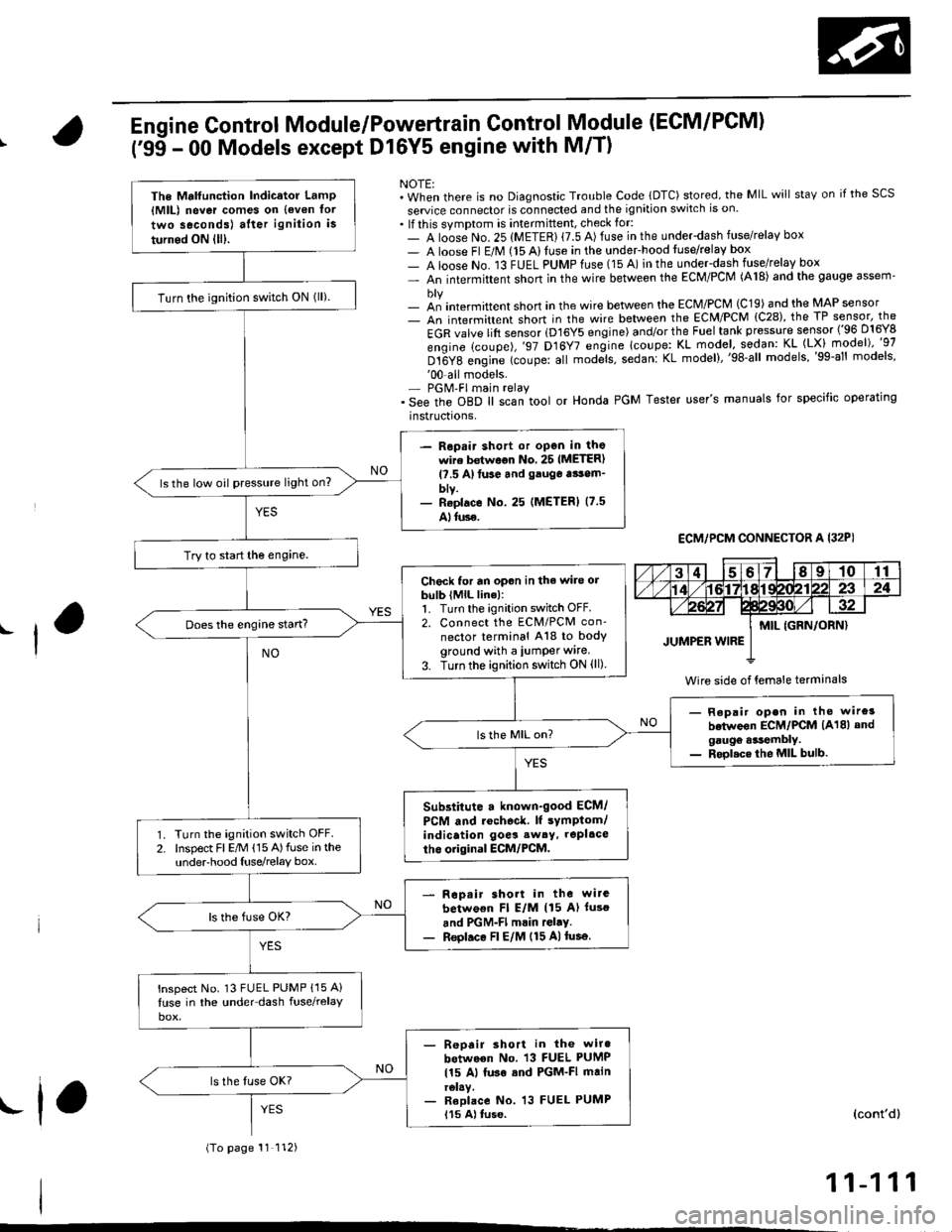
NOTE:. When there is no Diagnostic Trouble Code lDTC) stored, the MIL will staY on if the SCS
seruice connector is connected and the ignition switch is on.. lf this symptom is intermittent, check for:- A loose No. 25 (METER) {7.5 A) fuse in the underdash fuse/relay box- A loose Fl E/M (15 Alluse in the undeFhood fuse/relay box- A loose No. 13 FUEL PUMPfuse (15 A) in the under-dash fuse/relay box- An intermittent shon in the wire between the ECM/PCM (A18) and the gauge assem'
- an intermittent short in the wire between the ECM/PCM (C19) and the MAP sensor- An intermittent short in the wire between the ECM/PCM {C28), the TP sensor, the
EGR valve lift sensor (D16Y5 engine) and/or the Fuel tank pressure sensor ('96 D16Y8
engine (coupe),'97 D16Y7 engine lcoupe: KL model, sodan: KL (LX) model)"g7
Dt6Y8 engine (coupe: all mod;ls, sedanl KL model),'98-all models,'99-al' models''00-all models.- PGM'FI main relay. See the oBD ll scan tool or Honda PGM Tester user's manuals for specific operating
instructrons,
ECM,/PCM CONNECTOR A I32PI
Wire side of {emale terminals
The Mrlfunction Indicator LamP{MlL) never comes on {even tor
two seconds) after ignition is
turned ON lll).
Turn the ignition switch ON lll).
- Repair shott or open in thowire bstwoon No. 25 IMETER)l?.5 A)tuse and gauga tsom_blv.- Reolace No. 25 (METERI (7.5
Alluse.
ls the low oil pressure light on?
Try to start the engine.
Check for an opon in the wire orbulb (MlL line):1. Turn the ignition switch OFF.2. Connect the ECM/PCM con'
nector terminal A18 to bodyground with a iumper wire.
3. Turn the ignition switch ON (ll)
Does the engine start?
- Repair open in tho wire3
betwoon ECM/PCM (A18) andgaugo .*tembly.- Rool.ce the MIL bulb.
Substitute a known-good ECM/
PCM and rochoc&. lf sYmptom/indication goes sw6y, repl.ce
tho original ECM/PCM.Turn the ignition switch OFF.Inspect Fl E/M (15 A)fuse in theunderhood Iuse/relay box.
Rop.ir short in the wirc
betwo€n Fl E/M (15 A) luso
and PGM-Fl mrin rGl.y.Reol.ce Fl E/M (15 A)tusa.
lnspect No. 13 FUEL PUMP {15 A}
luse in the under-dash fuse/relay
- Reoair short in the wiro
between No. 13 FUEL PUMP
115 Al luse sod PGM-FI mainrelay.- Reolace No. 13 FUEL PUMP115 A) tuse.
(To page 11 112)
(cont'd)
11-111
.f,
Page 433 of 2189
PGM-FI System
Fuel Supply System
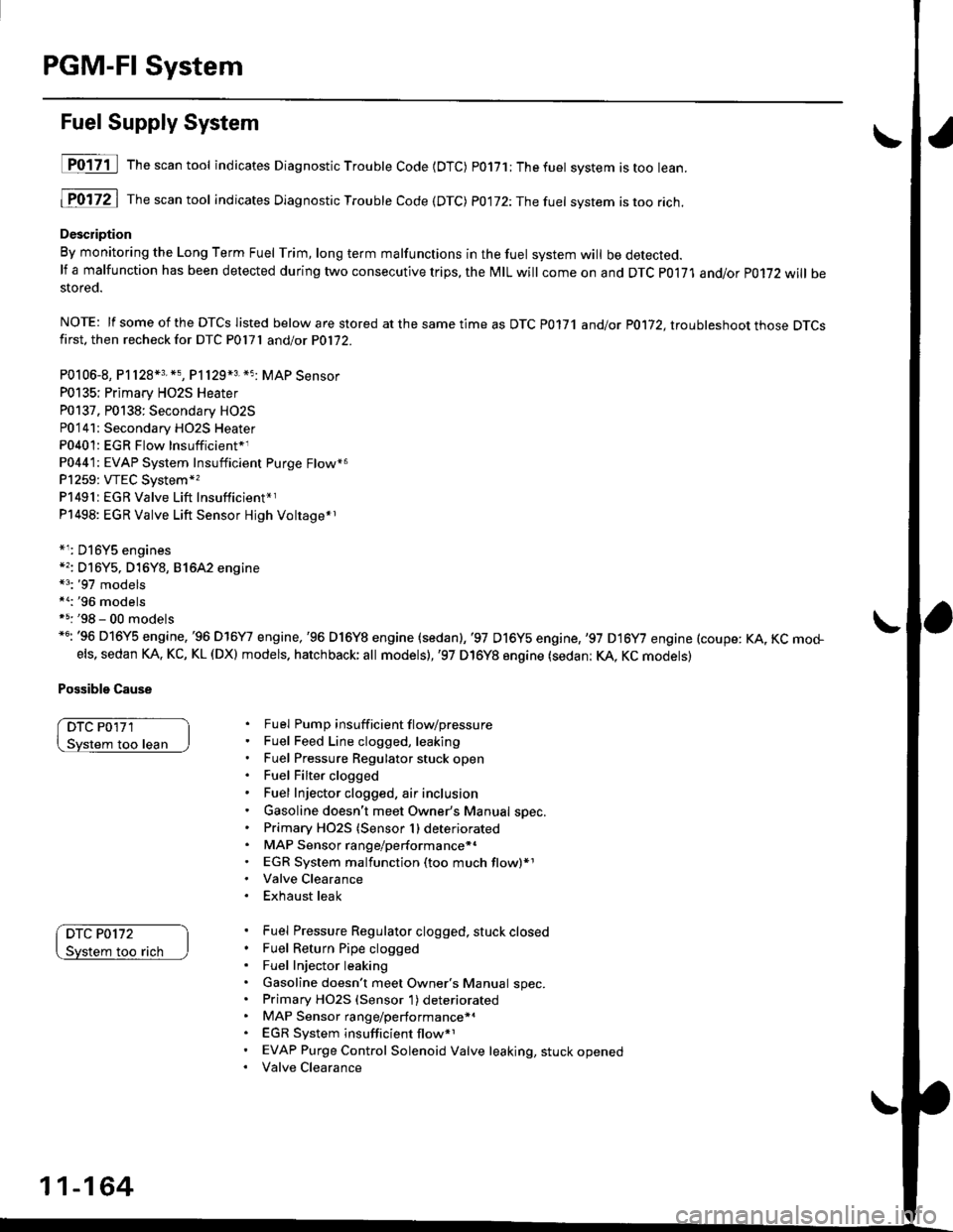
D017-il Th""""ntool indicates Diagnostic Troubte Code {DTC) p0171;Thefuet system istoo lean.
1P0172 | fne scan tool indicates Dlagnostic Trouble Code (DTC) P0172:Thefuel system istoo rich.
Description
By monitoring the Long Term Fuel Trim, long term malfunctions in the fuel system will be detected.lf a malfunction has been detected during two consecutive trips, the MIL will come on and DTC P0171 and/or P0172 will bestored.
NOTE: lf some of the DTCS listed below are stored at the same time as DTC P0171 andlot P0172, ltouhleshoot those DTCSfirst. then recheck for DTC P0l7l andlot P0172.
P0106-8, P1128*3. *5, P1129*3 *5 MAP Sensor
P0135; Primary HO2S Heater
P0137. P0138: Secondary HO2S
P0'141: Secondary HO2S Heater
P0401: EGR Flow Insufficient*1
P0441: EVAP System Insufficient Purge Flow*6
P1259: VTEC System*,
P1491:EGR Valve Lift Insufficient*r
P1498: EGR Valve Lift Sensor Hjgh Voltage*r
*r: D16Y5 engines*'�: Dl6Y5, D16Y8, 81642 engine*3: '97 models*a:'96 modelsf 5: '98 - 00 models*6: '96 D16Y5 engine,'96 D16Y7 engine,'96 D16Y8 engine (sedan),'97 D16y5 engine,,97 D16y7 engine (coupe: KA, KC mo+els, sedan KA. KC, KL (DX) models. hatchback; all models),'97 D16Y8 engine (sedan: KA, KC models)
Possible Cause
DTC P0'171
loo lean
DTC P0172
too rach
Fuel Pump insuff icient f lovpressure
Fuel Feed Line clogged, leaking
Fuel Pressure Regulator stuck open
Fuel Filter clogged
Fuel Injector clogged, air inclusion
Gasoline doesn't meet Owner's Manual spec.
Primary HO2S (Sensor 1) deteriorated
MAP Sensor range/performance*.
EGR System malfunction (too much flow)*1
Valve Clearance
Exhaust leak
Fuel Pressure Regulator clogged, stuck closed
Fuel Return Pipe clogged
Fuel Injector leaking
Gasoline doesn't meet Owner's Manual spec.Primary HO2S (Sensor 1) deteriorated
MAP Sensor range/performance*a
EGR System insufficient flow*1
EVAP Purge Control Solenoid Valve leaking, stuck opened
Valve Clearance
11-164
Page 523 of 2189
Emission Control System
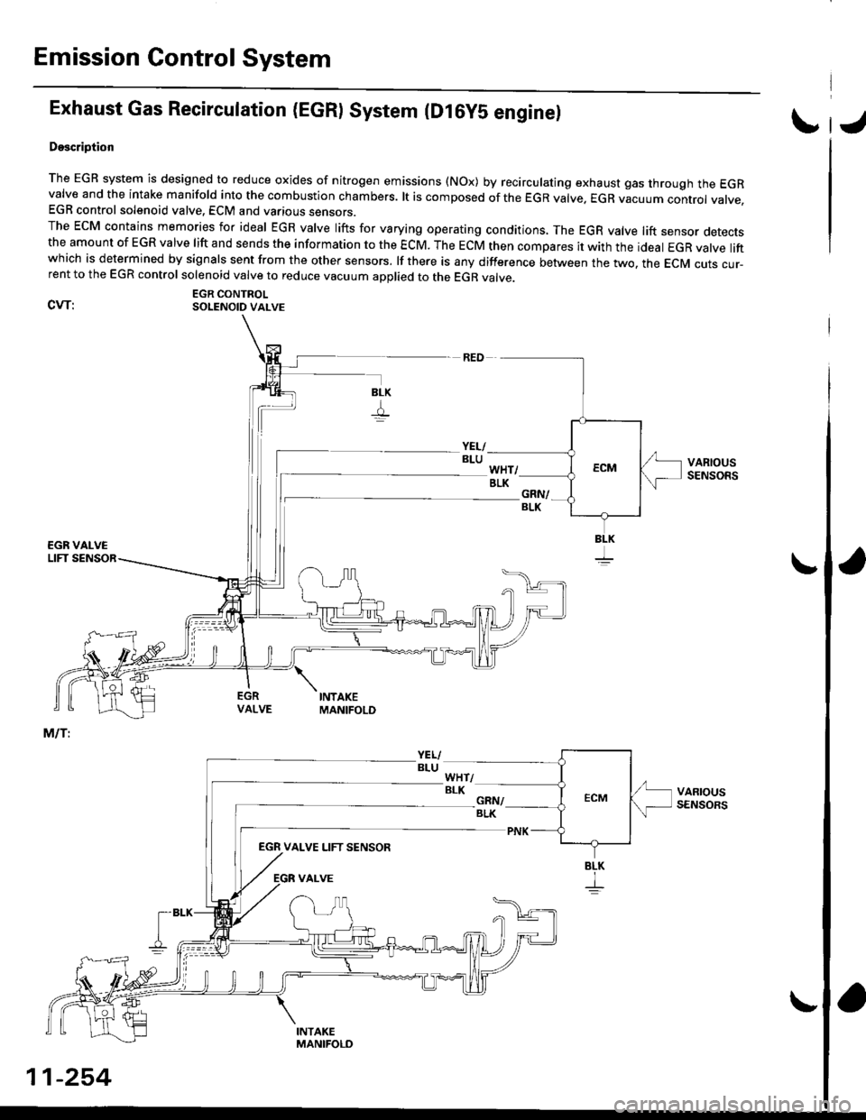
Exhaust Gas Recirculation (EGR) System (D16yS engine)
Doscription
The EGR system is designed to reduce oxides of nitrogen emissions (NOx) by recirculating exhaust gas through the EGRvalve and the intake manifold into the combustion chambers. lt is composed of the EGR valve. EGR vacuum conrrot vatve.EGR control solenoid valve. ECM and various sensors.The EcM contains memories for ideal EGR valve lifts for varying operating conditions, The EGR valve lift sensor detectsthe amount of EGR valve lift and sends the information to the ECM. The ECM then compares it with the ideat EGR valve liftwhich is determined by signals sent from the other sensors. lf there is any difference between the two. the EcM cuts cur-rent to the EGR control solenoid valve to reduce vacuum applied to the EGR valve.
EGR CONTROLCVT: SOLENoID vALvE
EGN VALVE LIFT SENSOR
BLK
I
I
11-254
Page 525 of 2189
Emission Control System
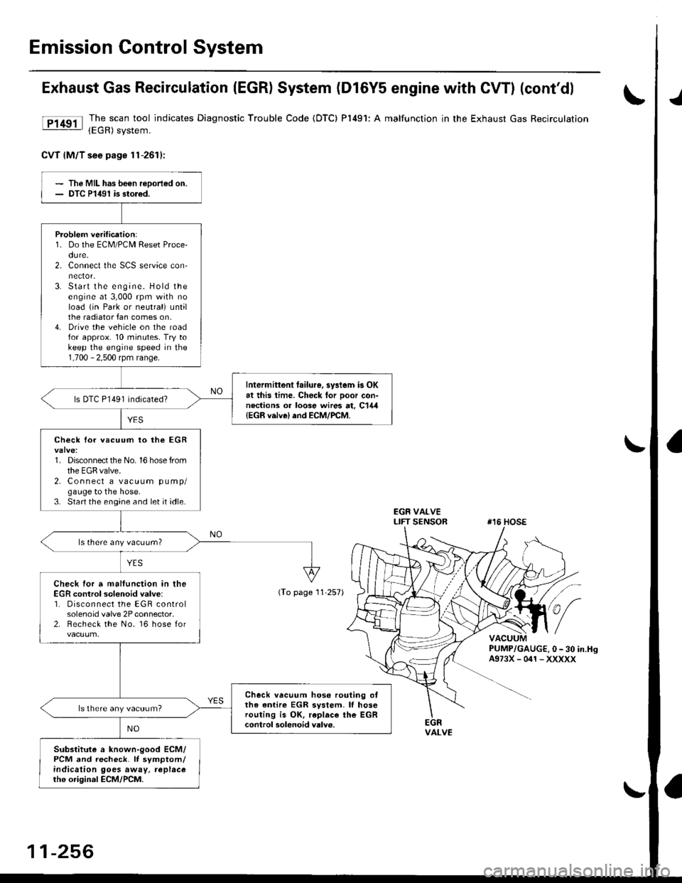
Exhaust Gas Recirculation (EGR) System (D16Y5 engine with GWI (cont'dl
lTl49il T_he scan tool indicates Diagnostic Trouble Code (OTC) P1491: A malfunction in the Exhaust Gas Recirculation- lEgh) svstem.
CvT lM/T see page 1l-2611:
J
EGR VALVELIFT SENSOR#16 HOSE
PUMP/GAUGE,0- 30 in.HsA973X-041-XXXXX
EGRVALVE
The MIL has been reoorted on.DTC P1491 is stoled.
Problem verification:1. Do the ECM/PCM Reset Proce-du re.2. Connect the SCS service con'
3. Start the engine. Hold theengine at 3,000 rpm with noload {in Park or neutral) untilthe radiator fan comes on,4. Drive the vehicle on the roadfor approx. 10 minutes. Try tokeep the engine speed in the1,700 - 2,500 rpm range.
Intermittonl failure, system is OKat this time. Check for Door con-nections or loose wires at, C144{EGR velve} and ECM/PCM.
ls DTC P l49l indicated?
Check fo. vacuum to ihe EGR
1. Disconnect the No. 16 hose fromthe EGR valve.2. Connect a vacuum pump/gauge to the hose.3. Start the engine and let it idle.
ls there any vacuum?
Check tor a malfunction in theEGR control solenoid valve:'1. Disconnect the EGR controlsolenoid valve 2P connector,2. Becheck the No. 16 hose for
Check vacuum hose routing o,the entire EGR svstem. lf hoserouting is OK, replac€ the EGRcontrol solenoidvalv6.
ls there any vacuum?
Substitute a known-good ECM/PCM and recheck. It symptom/indicalion goes away, replacethe original ECM/PCM.
(To page 11 257)
11-256
Page 526 of 2189
![HONDA CIVIC 1999 6.G Owners Manual \EGR VALVELIFT SENSOR#16 HOSE
I
(From page 11-256)
EGR VALVE LIFT SENSOR3P CONNECTOR lC14.l)
zF vcczI- . ] IYEL/BLU)ll 2l3l---l-r_ 7 |
v-,, ISG2IGRN/BLK) I ^ II{Vts
ECM CONNECTOR D {16P)
PUMP/GAUGE,0 HONDA CIVIC 1999 6.G Owners Manual \EGR VALVELIFT SENSOR#16 HOSE
I
(From page 11-256)
EGR VALVE LIFT SENSOR3P CONNECTOR lC14.l)
zF vcczI- . ] IYEL/BLU)ll 2l3l---l-r_ 7 |
v-,, ISG2IGRN/BLK) I ^ II{Vts
ECM CONNECTOR D {16P)
PUMP/GAUGE,0](/img/13/6068/w960_6068-525.png)
\EGR VALVELIFT SENSOR#16 HOSE
I
(From page 11-256)
EGR VALVE LIFT SENSOR3P CONNECTOR lC14.l)
zF vcczI- . ] IYEL/BLU)ll 2l3l---l-r_ 7 |
v-,, ISG2IGRN/BLK) I ^ II{Vts
ECM CONNECTOR D {16P)
PUMP/GAUGE,0 - 30 in.Hs4973X-041-XXXXX
sG2(GRN/BLKIvcc2IYEL/BLU}
Wire side ol temale terminals
PCM CONNECTORS C (31P}'
YES
Wire side of female terminals
1
(cont'd)
1-257
Check fo. a mallunction in theEGF valv€:1. ldove the vacuum pump/gauge
to the EGR valve.2. With the engine at idle, apply
26.7 kPa (200 mmHg,8.0 in.Hg)
ofvacuum to the EGR valve.
Does the engine stall or runrough and does the EGR valvehold vacuum?
Check for an open in the wire
IVCC2linel:1. Turn the ignition switch OFF.2. Disconnect the EGR valve liftsensor 3P connector.3. Turn the ignition switch ON (ll).
4. Measure voltage between theEGR valve lift sensor 3P con'
nector terminals No. 3 and
No.2.
ls lhere approx.5 V?
Check for an oDen in the wire
{VCC2 line}:Measure voltage between theECM/PCM connector terminalsD10 and Dl1 (C18 and C28)*.
Rep.ir open in the wire betweenrhe EGR valve snd ECM/PCM
{Dl0 {C28)*).lsthere approx.5 V?
Sub3titute t known-good ECM/PCM end recheck. lt 3ymptom/indication goos eway, replaceth6 original ECM/PCM.(To page 1l-258)*: '99 - 00 models
Page 527 of 2189
Emission Gontrol System
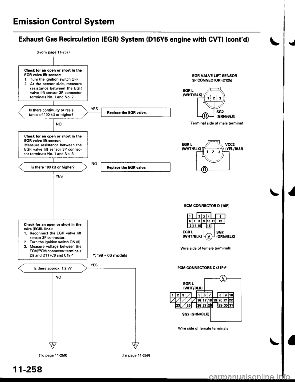
Exhaust Gas Recirculation (EGRI System (Dl6Y5 engine with CW) (cont'dl
EGR VALVE LIFT SENSOR3P CONNECTOR {Cl251
./
EGR L(WHT/BLKI
EGR LIWHT/BLKI
EGR L{WHT/BLKI
sG2
{GRN/BLK}
sG2{GRN/BLK}
Terminal side ol male terminal
ECIT'I CONNECTOR D II6PI
Wir€ side of f€male terminals
PCM CONNECTORS C (31PI*
{To page 11-259)
11-258
{From page 11-257}
Chock lor an opcn or short in th.EGR v.lve lift .€nsor'1. Turn the ignition switch OFF.2. At the sensor sid€, measur€resistance between the EGRvalve lift sensor 3P connectorterminals No. 1 and No.2.
ls there continuity or resis'tance ot 100 k0 or higher?
Chock tor sn op€n or lhort in theEGR valve lift lonror:Measure resistancg between theEGR valve lift s€nsor 3P connec-tor terminals No. 1 and No. 3.
ls there 100 k0 or higher?
Ch.ck tor an ooon or rhon in thcwiro IEGRL linc):1. Beconnect tho EGR v6lve liftsensor 3P connector.2. Turn tho ignition switch ON (ll).
3. Measure voltage between theECM/PCM connector terminalsD9 and Dl1 (C6 and C18l*.
ls there approx. 1.2 V?
(To page 11-259)
Wire side of female terminals
Page 534 of 2189
J\
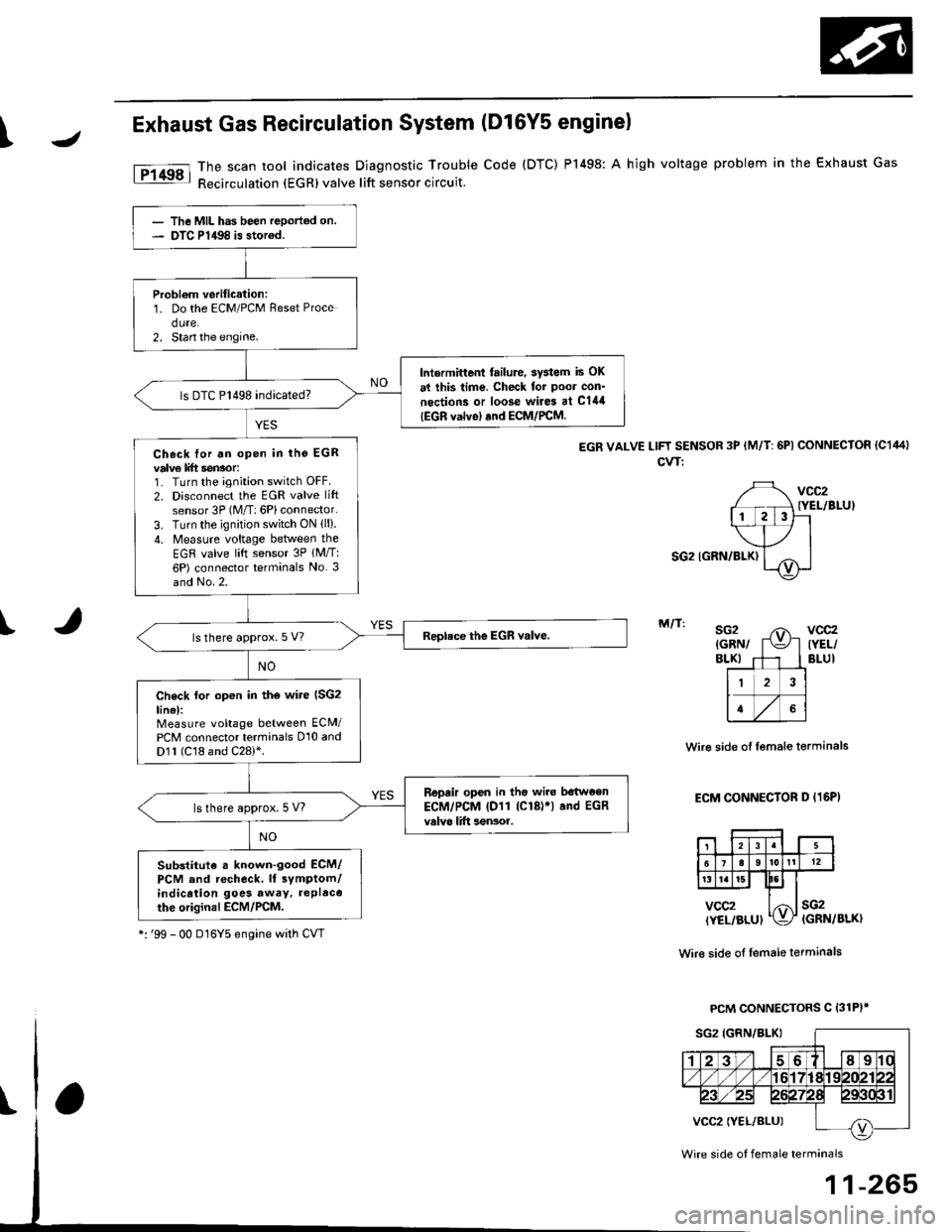
Exhaust Gas Recirculation System
The scan tool indicates Diagnostic Trouble
Recirculation (EGRlvalve lift sensor circuit.
(D16Y5 enginel
Code {DTC) P1498: A high voltage problem in the Exhaust Gas
EGR VALVE LlFf SENSOR 3P {M/T: 6Pl CONNECTOR (C1441
cvT:
vcc2{YEL/BLUI
SG2 IGRN/BLK)
IM/T:sG2{GRN/BLKI
Wir€ side ol lemale terminals
ECM CONNECTOR D (16P)
vcc2(YEL/BLUIsG2(GRN/BLK)
Wir€ side of female terminals
PCM CONNECTORS C 131P)'
Wire side oI female terminals
11-265
- The MIL has been reportod on.- DTC P1498 is storod.
Probl€m verification:1. Do the ECM/PCM Reset Proce
dure.2. Stan the engine.
Intermittent tailure, sy3lem is OK
at lhis time. Check tor poor con'
nections or loose wire3 at C144
|EGR valvel and ECM/PCM.
ls DTC P1498 indicated?
Check for an open in tho EGRvalv6 lift sen3or:1. Turn the ignition switch OFF.
2. Disconnect the EGR valve lift
sensor 3P (M/T: 6Pl connector.
3. Turn the ignition switch ON (ll).
4. Measure voltage between the
EGR valve litt sensor 3P lM/T:6P) connector terminals No. 3and No.2.
ls there approx.5 V?
Check lor op€n in th€ wire (SG2
line):Measure voltage between ECM/PCM connector terminals 010 andD1l (C18 and C28)*.
Repair open in tho wiro betwoen
ECM/PCM lDl1 (Cl8)r) and EGR
valvo lift sensor.ls there approx. 5 V?
Substitute . known-good ECM/PCM and recheck. ll symptom/indicrtion goes away, replacothe original ECM/rcM.
*:'99 - 00 D16Y5 engine with CVT
Page 535 of 2189
Emission Control System
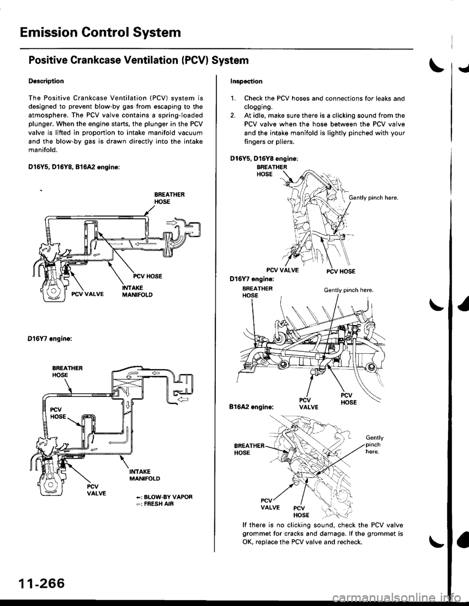
Positive Crankcase Ventilation IPCVI System
Descripiion
The Positive Crankcase Ventilation (PCV) system is
designed to prevent blow-by gas from escaping to the
atmosphere. The PCV valve contains a spring-loaded
plunger. When the engine starts, the plunger in the PCV
valve is lifted in proportion to intake manifold vacuum
and the blow-by gas is drawn directly into the intake
manifold.
D15Y5, D16Y8, 816A2 ongins:
BREATHERHOSE
Dl6'|11 6ngin6:
-: aLOW-BY VAPOR-: FnESH AIF
11-266
tJ
lrcpection
1. Check the PCV hoses and connections for leaks and
clogging.
2. At idle, make sure there is a clicking sound from the
PCV valve when the hose between the PCV valve
and the intake manifold is lightly pinched with your
fingers or pliers,
D16Y5, D16Y8 ongins:
BREATHERHOSE
PCV VALVE
Gently pinch here.
Bl6A2 engins:VALVE
lf there is no clicking sound, check the PCV valve
grommet for cracks and damage. If the grommet is
OK, replace the PCV valve and recheck.
PCV