Lug nut HONDA CIVIC 1999 6.G Owner's Manual
[x] Cancel search | Manufacturer: HONDA, Model Year: 1999, Model line: CIVIC, Model: HONDA CIVIC 1999 6.GPages: 2189, PDF Size: 69.39 MB
Page 1104 of 2189
Steering Gearbox
Removal {cont'dl
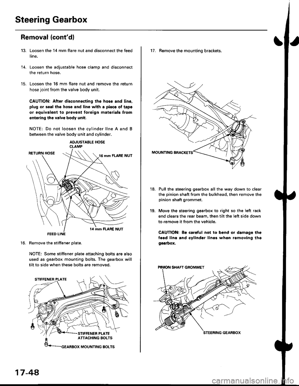
Loosen the 14 mm flare nut and disconnect the feed
line.
Loosen the adjustable hose clamp and disconnect
the return hose.
Loosen the 16 mm flare nut and remove the return
hose joint trom the valve body unit.
CAUTION: After disconnecting lhe hos6 and lin6.
plug or seal the hose and line with a pioca ol tapa
or equivalent to prevenl foreign matorials trom
entsring the valve body unit.
NOTE: Do not loosen the cvlinder line A and
between the valve body unit and cylinder.
ADJUSTABLE HOSECLAMP
Remove the stiffener Dlate.
NOTE: Some stiffener plate attaching bolts are also
used as gearbox mounting bolts. The gearbox will
tilt to side when these bolts are removed.
13.
14.
t9.
16.
17-48,
17. Remove the mounting brackets.
Pull the steering gearbox all the way down to clear
the pinion shaft from the bulkhead. then remove the
pinion shaft grommet.
Move the steering gesrbox to right so the left rack
end clears the rear beam, then tilt the left side down
to remove it from the vehicle,
CAUTION: Be careful not io bend or damage the
fagd ling and cylindsr lin99 whgn rgmoving thg
ggarbox,
18.
STEERING GEANEOX
Page 1139 of 2189
I
NOTE: Wash the knuckle and hub thoroughly in
high flash point solvent before reassembly.
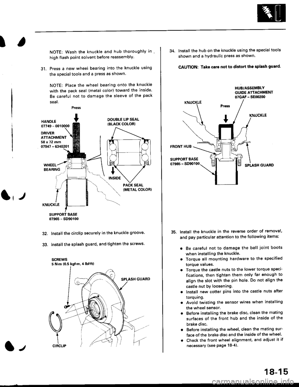
31. Press a new wheel bearing into the knuckle using
the specialtools and a press as shown
NOTE: Place the wheel bearing onto the knuckle
with the pack seal (metal color) toward the inside
Be careful not to damage the sleeve of the pack
seal.
Press
HANOI.E07749 - 001
DRIVERATTACHMENT58x72mm07947 - 6340201
DOUBLE LIP SEAL
{BLACK COLOR)
KNUCKLE
SUPPORT BASE07965 - SD90100
Installthe circlip securely in the knuckle groove'
Installthe splash guard, and tighten the screws.
scREws5 N.m (0.5 kgd m, 4lbt'ft)
32.
33.
l-,
18-15
34. lnstall the hub on the knuckle using the specialtools
shown and a hydraulic press as shown.
CAUTION: Take care not to distort tho splash gusrd'
HUB/ASSEMBLYGUIDE ATTACHMENT07GAF- SEflt2d)
KNUCKLE
FRONT HUB
SUPPORT BASE
07966 - StXx)100SPLASH GUARD
tnstall the knuckle in the reverse order of removal'
and pay particular attention to the following items:
. Be careful not to damage the ball joint boots
when installing the knuckle.
. Torque all mounting hardware to the specified
torque valugs.
. Torque the castls nuts to the low€r torque specl-
fications, then tighten them only far enough to
align the slot with the pin hole. Do not align the
castle nut by loosening.
. lnstall new cotter pins into the castle nuts after
torquing.
. Avoid twistin0 the sensor wires when installing
the wheel ssnsor.
. Before installing the brake disc, clean the mating
surfaces of the front hub and the inside of the
brake disc.
. Before installing the wheel, clean the mating sur-
face ofthe brake disc and the inside of the wheel
. Check the front wheel alignment, and adjust it if
necessary (see page 18-4).
Page 1228 of 2189
\il
Modulator Unit
RemovaUlnstallation
CAUTION:
. Do not spill brake tluid on the car; it may damage the paint; it brako lluid does contact the paint, wash it off immedi-
ately with wator.
a Take care not to damage or delorm the brake lin€s during removal and installation.
. To prevent the brake tluid from tlowing, plug and cover the hose €nds and ioints with a shop tow6l or equivalent
mat€rial.
NOTE| Tightentheflare nutsto 15 N.m (1.5 kgnm. l1 lbf.ft).
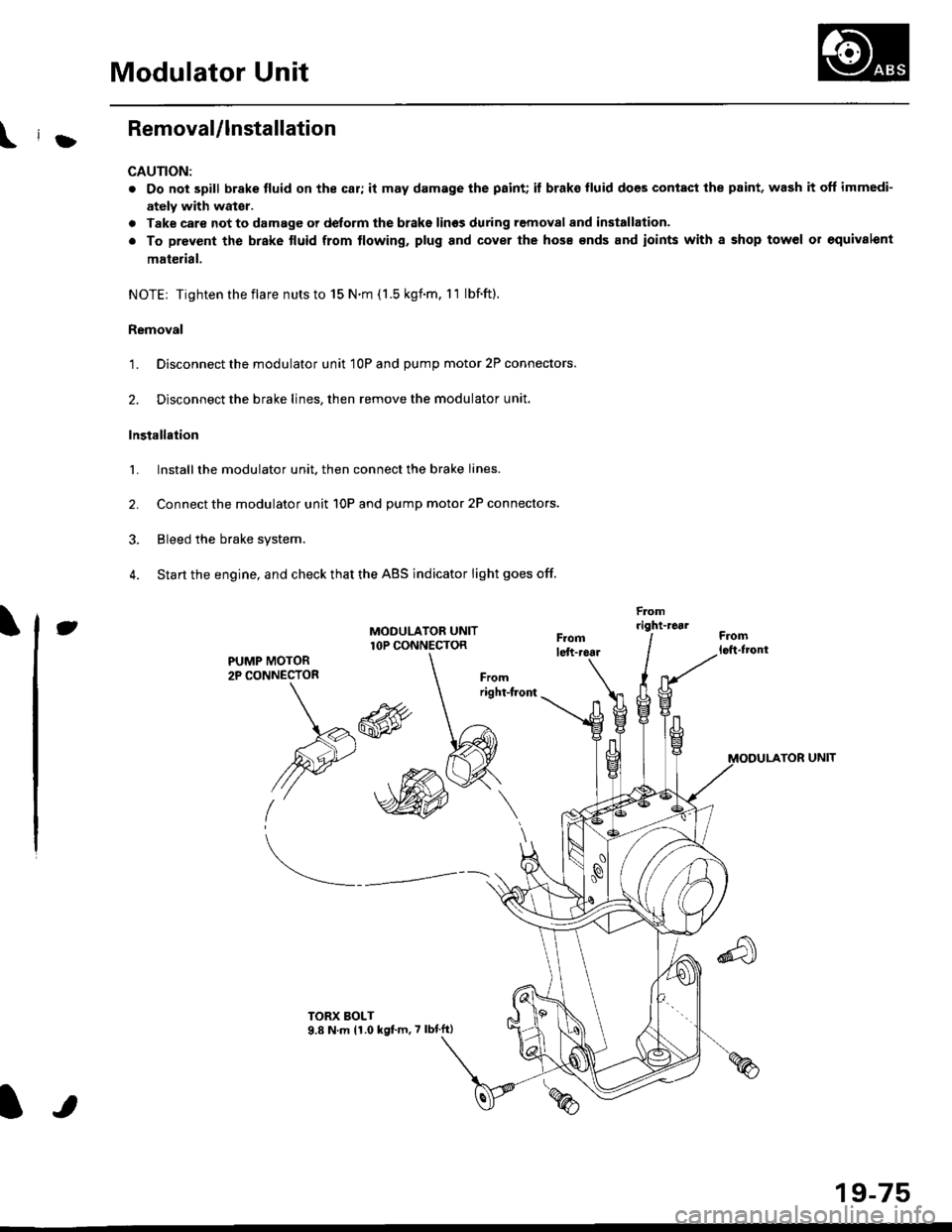
Removal
'1. Disconnect the modulator unit 10P and Dump motor 2P connectors.
2. Disconnect the brake lines, then remove the modulator unit.
Installaiion
1. Install the modulator unit. then connect the brake lines.
2. Connect the modulator unit 10P and oumD motor 2P connectors.
3. Bleed the brake system.
4. Start the engine, and check that the ABS indicator light goes off.
Fomright-1461
PUMP MOTOR2P CONNECTOR
J
-R
/2e'
t'
TOR UNIT
tt
19-75
Page 1452 of 2189
Evaporator
1.
Replacement
4.
Move the temperature control to "HOl"
'96-98: Slide the temoerature control lever.'99-00: Turn the ignition switch ON (ll), then turn
the temperature contol knob. Turn the ignition
switch off.
Remove the battsry.
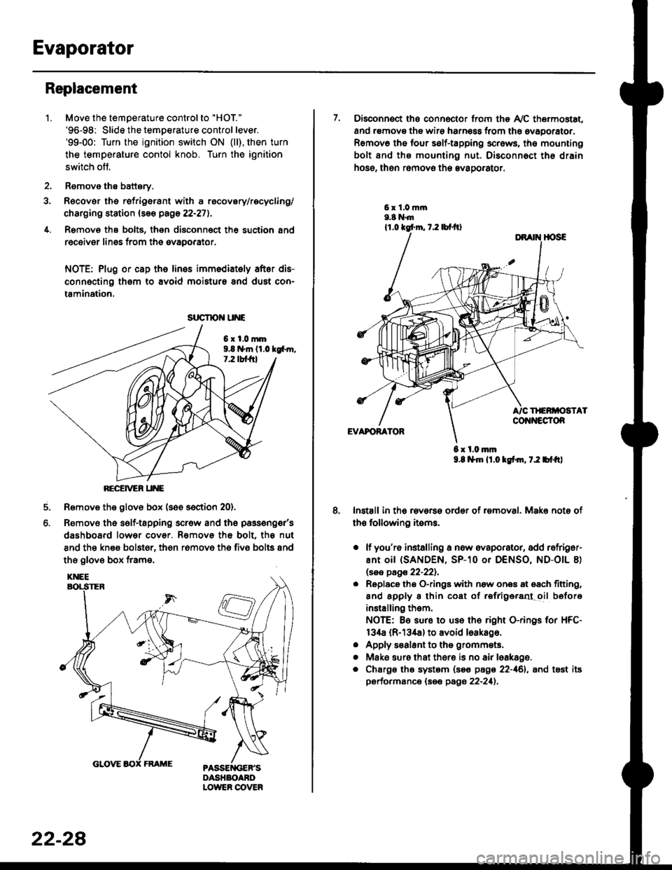
Rgcover the refrigerant with a rocovery/recycling/
charging station (see page 22-271.
Remove the bolts, then disconnect th6 suction 8nd
receiver lines from th6 evaoorator.
NOTE: Plug or cap the lines imm€diatoly after dis-
connecting them to avoid moisture and dust con-
tamination.
6xl.0mm9.8 n*ln ll.0 tg6m.7.2 lbt frl
RECEiVER UNE
Remove the glov6 box (see section 20).
Removo the self-tapping scr€w and the passeng€r's
dashboard lower cover. Removs the bolt. the nut
8nd the kn€e bolst6r, th6n r6mov6 th6 fiv6 bolts and
the glove box frame.
6.
srrcrrc u E
22-28
7. Disconnect the connector from th€ Ay'C thermostat,
and r€movs the wire harness from the ovaporator.
Remov6 tho four self-tapping screws, tho mounting
bolt and ths mounting nut. Disconnect th€ drain
hose, then remov€ th6 avagorator.
6 x l.0.nm9.8 l$m lt.o ldm, 7.2 bl.tt)
Install in the reverse order of removal. Make note of
th€ following items.
o lf you'r6 installing a new evaporator, add rofriger-
ANt OiI {SANDEN, SP-10 Or DENSO, ND-OIL 8)
lsas page 22-221.
. Replace the O-rings with now ones 8t 68ch titting,
and apply 8 thin coat of r€frlgersd oil before
installing them.
NOTE: Be sure to use the right O-rings for HFC-
134a (R-134a) to avoid loakago.
. Apply s€alant to tha grommets.
. Mske sure that ther€ is no air leakage.
. Chargs ths system {s€€ page 22-161, and tost its
performance (see pags 22-211.
Page 1454 of 2189
Compressor (SANDENI
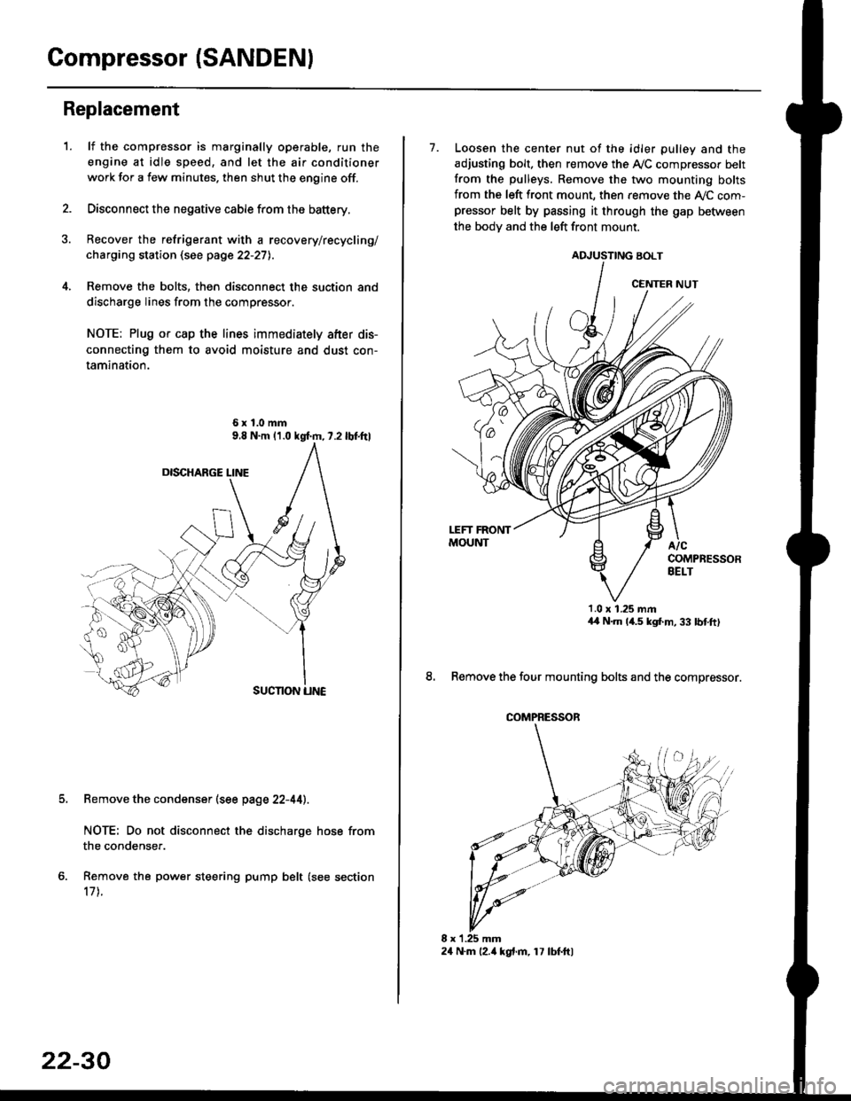
Replacement
1.lf the compressor is marginally operable, run the
engine at idle speed, and let the air conditioner
work for a few minutes. then shut the engine off.
Disconnect the negative cable from the battery.
Recover the refrigerant with a recovery/recycling/
charging station (see page 22-27l..
Remove the bolts, then disconnect the suction and
discharge lines from the compressor.
NOTE: Plug or cap the lines immediately after dis-
connecting them to avoid moisture and dust con-
tamination.
6xl.0mm
Remove the condenser (see page 22-44).
NOTE: Do not disconnect the discharge hose from
the condenser.
Remove the power steering pump belt (see section
17 t.
22-30
24 N.m l2.ia kgt.m, 17 lbf.ftl
7. Loosen the center nut of the idler pulley and the
adjusting bolt. then remove the A,/C compressor belt
from the pulleys. Remove the two mounting bolts
from the left front mount, then remove the ly'C com-pressor belt by passing it through the gap befiiveen
the bodv and the left front mount.
ADJUSTING BOLT
1.0 x 1.25 mmaa N.m 14.5 kgf,m, 33 bnft)
8. Remove the four mounting bolts and the compressor.
CENTER NUT
COMPRESSOR
Page 1461 of 2189
Compressor (DENSO)
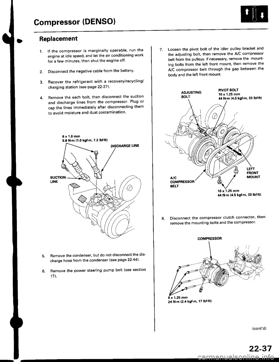
Replacement
1.lf the compressor is marginally operable, run the
engine at idle speed, and let the air conditioning work
for a few minutes, then shut the engine off
Disconnect the negative cable from the battery'
Recover the refrigerant with a recovery/recycling/
charging station lsee page 22-271
Remove the each bolt, then disconnect the suction
and discharge lines from the compressor' Plug or
cap the lines immediately after disconnecting them
to avoid moisture and dust contaminatlon.
6 x '1.0 mm9.8 N.m (1.0 kgf m,7.2 lbfft)
Remove the condenser, but do not disconnect the dis-
charge hose from the condenser (see page 22-441'
Remove the power steering pump belt (see sectron
17]-.
7. Loosen the pivot bolt of the idler pulley bracket and
the adjusting bolt. then remove the A,/C compressor
belt from the pulleys. lf necessary, remove the mount-
ing bolts from the left front mount. then remove the
fuC compressor belt through the gap between the
bodv and the left front mount.
'10 x 1,25 mm4,0 N.m (,1.5 kgf'm. 33 lbt ftl
Disconnect the compressor clutch connector, then
remove the mounting bolts and the compressor'
PIVOT BOLT10 x 1.25 mm4,1 N.m (4.5 kgt'm,33 lbfft)
COMPRESSOR
24 N.m (2.4 kgf m, 17 lbf ftl
(cont'd)
22-37