connection HONDA CIVIC 1999 6.G Owner's Manual
[x] Cancel search | Manufacturer: HONDA, Model Year: 1999, Model line: CIVIC, Model: HONDA CIVIC 1999 6.GPages: 2189, PDF Size: 69.39 MB
Page 315 of 2189
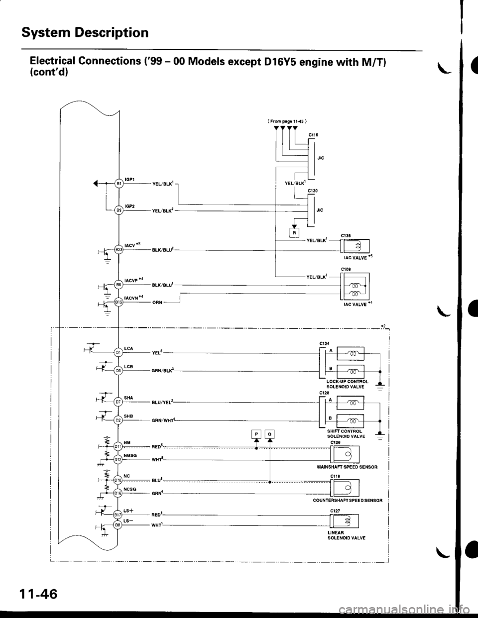
System Description
Electrical Connections ('99 - 00 Models except Dl6Y5 engine with M/Tl
(cont'd)
cl09
racvP*{- BLK/eLu-lqt
pl
MAINSHAFT SPEEO SENSOR
clla
COUN'IERSHAFTSPEED SENSOR
c121
tt I I
UNEARSOL€NOIDVALVE
SOLENOID VALVE --
11-46
Page 317 of 2189
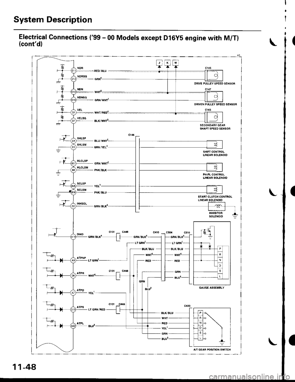
System Description
Electrical Connections ('99 - 00 Models except Dl6Y5 engine with M/Tl
(cont'dl
DRIVE PULIEY SPEEO SENSOF
SECONDAFY GEAFSHAFT SPEEO SENSOR
SCLSM
INHSOL
PNK/BLK
YE!'
PNK/BIU
cnvauC
c131 CrKa
GFN/Brf I f cnvsuCL_
,T GEAF POSII|ON SWITCH
11-48
Page 319 of 2189
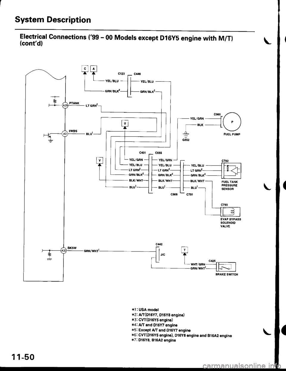
System Description
Electrical Connections ('gg - 00 Models except Dl6y5 engine with M/Tl(cont'd)
CsO5 -r-\- YELI6RN f/ \It P I
'- BLK __1 /
I \'----l
Ft,EL PUMP
EVAP BYPASSSOLENOIDVALVE
ft ti-l
I lJ/c TT__l It.] I c425 __
I LwHr GRN {-l_cnnzwm'_{h\_, IaBAKE StlflTCB
*l : USA mod6l*2: A/T(Di6W, Dt6Y8 engine)*3: CW(DI6Y5 engino)*4: A,rT e16 915y7 "nn,n"*5: ExceB AfT and Dl6Y7 engine,16: Cyr(DI6Y5 €n9ine), D16y8 engine and B,tOA2 engins*7: Dl5Y8, 816A2 engine
Elt^-l'tF'tF q23 r_ c446
I L vever-u - l l-- ,.,- ,.u
t|lL-- cnrzer-rc-{f cnnzar-x,
YEL/GRN
YEVELU
- YEL/GRN- YEVBLU
lr cat'�_ LT GRN2qar/auC- qaN/eud
BLVWHf- BLK/WiT
BLIII- BLul
1 1-50
Page 353 of 2189
Troubleshooting
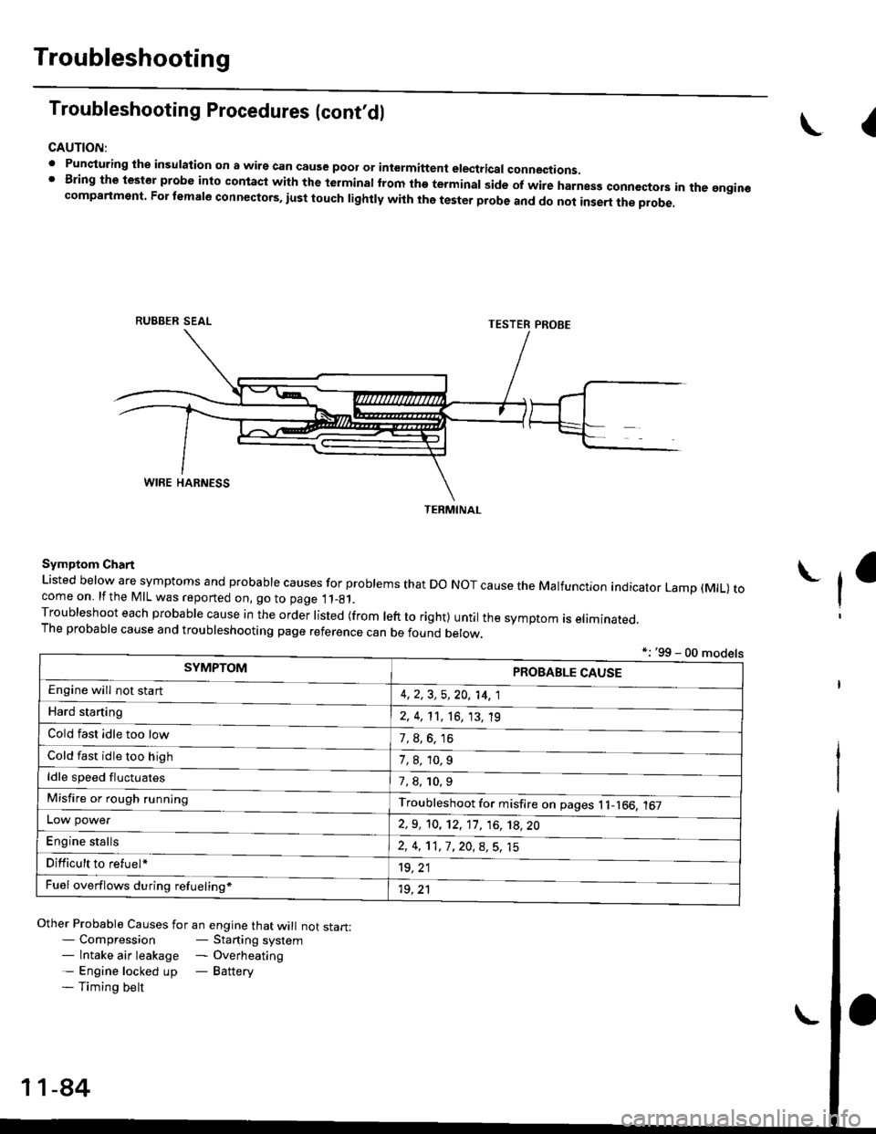
Troubleshooting Procedures (cont,dl
CAUTION:
. Punqturing ihe insulation on a wirs can cause poor or intermiftent electricar connections.I Bring the test€r probe into contacl with the terminatlrom the terminal side of wire harnesg conncctors in the gngin€compartment. For temale connectors, iust touch lightly with the tester probe and do not inse.t the probe.
\I
RUBBER SEAL
Other Probable Causes for an engine that will not start:- Compression- Starting system- lntake air leakage - Overheating- Engine locked up - Battery- Timing belt
TESTER PROBE
Symptom Chart
Listed below are symptoms and probable causes for problems that Do NoT cause the Malfunction indicator Lamp (MlL) tocome on. lfthe MIL was reported on, go to page 11_81.Troubleshoot each probabre cause in the order risted (from reft to right) untir the symptom is eriminated.The probable cause and troubleshooting page reference can be found berow.
L
*: '99 - 00 models
TERMINAL
SYMPTOMPROBABLE CAUSE
4,2,3, 5,20, 14, 1
2, 4, 11, 16, 13, 't9
?, s^6. 16
1,8,10.9
Engine will not sta rt
Hard starting
Cold fast idle too low
Cold fast idle too high
ldle speed fluctuates7,8, 10.9
Troubleshoot for misfire on pages l1-166, 167Misfire or rough running
LOW power
E"g|* "t"lb
2,9, 10, 12, 11, 16, 't8,20
2,4,11,7,20,8,5,15
't9, 21
1r, ,1
Difficult to refuel*
Fuel overflows during refueling*
11-84
Page 366 of 2189
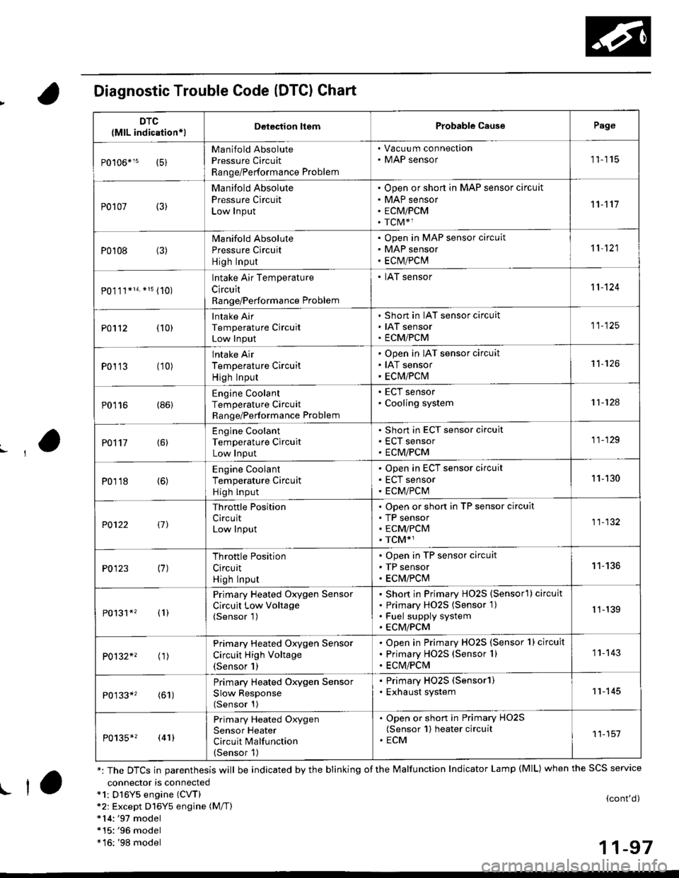
Diagnostic Trouble Code (DTCI Chart
connector is connecteda1: Dl6Y5 engine (CVT)*2: Except D16Y5 engine (M/T)*14:'97 model*15:'96 model*16: '98 model
(cont'd)
11-97
DTC
{MlL indication*lDelection liemProbable CausePage
Manifold Absolute
Pressure Circuit
Range/Performance Problem
. Vacuu m connection. MAP sensor11115
P0107 (3)
Manifold Absolute
Pressure Circuit
Low Input
Open or short in MAP sensor circuit
MAP sensor
ECMiPCM
TCM*1
11't1'l
P0108 (3)Manifold Absolute
Pressure Circuit
High Input
Open in MAP sensor circuit
MAP sensor
ECtvt/PCM
't 1 121
P0.111*14. *15 (10)
lntake Air Temperature
Circuit
Range/Performance Problem
. IAT sensor11-124
PO112 {10}
Intake Air
Temperature Circuit
Low Input
Short in IAT sensor circuit
IAT sensor
ECMiPCM
11-125
P0113 (10)lntake Air
Temperature Circuit
High Input
Open in IAT sensor circuit
IAT sensor
ECM/PCM
't1-126
P0116 (86)Engine Coolant
Temperature Circuit
Range/Performance Problem
. ECT sensor. Cooling system11-124
PO't't7 {6)
Engine Coolant
Temperature Circuit
Low Input
Short in ECT sensor circuit
ECT sensor
ECM/PCM
11-129
P0118 (6)Engine Coolant
Temperature Circuit
High lnput
Open in ECT sensor circuit
ECT sensor
ECM/PCM
11-130
?0122 t1l
Throttle Position
CircuitLow Input
Open or short in TP sensor circuit
TP sensorECM/PCM
TCM*1
11-132
P0123 (7)Throttle Position
Circuit
High Input
Open in TP sensor circuit
TP sensor
ECM/PClvl
11-136
P0131*' (1)
Primary Heated Oxygen Sensor
Circuit Low Voltage(Sensor 1)
Short in Primary HO2S (Sensorl ) circuit
Primary HO2S {Sensor 1)
Fuel supply system
ECM/PCM
1 1-139
P0132*' ('�r)
Primary Heated Oxygen Sensor
Circuit High Voltage(Sensor 1)
Open in Primary HO2S {Sensor 1} circuit
Primary HO2S (Sensor 1)
ECM/PCM
1 1- 143
P0133*' (61)
Primary Heated Oxygen Sensor
Slow Response(Sensor 1)
. Primary HO2S (Sensorl). Exhaust system11-145
P0135*? (41)
Primary Heated Oxygen
Sensor Heater
Circuit Malfunction(Sensor 1)
. Open or short in Primary HO2S(Sensor 1) heater circuit. ECM11-151
*: The DTCS in parenthesis will be indicated by the blinking of the Malfunction Indicator Lamp (MlL) when the SCS service
! ta
Page 370 of 2189
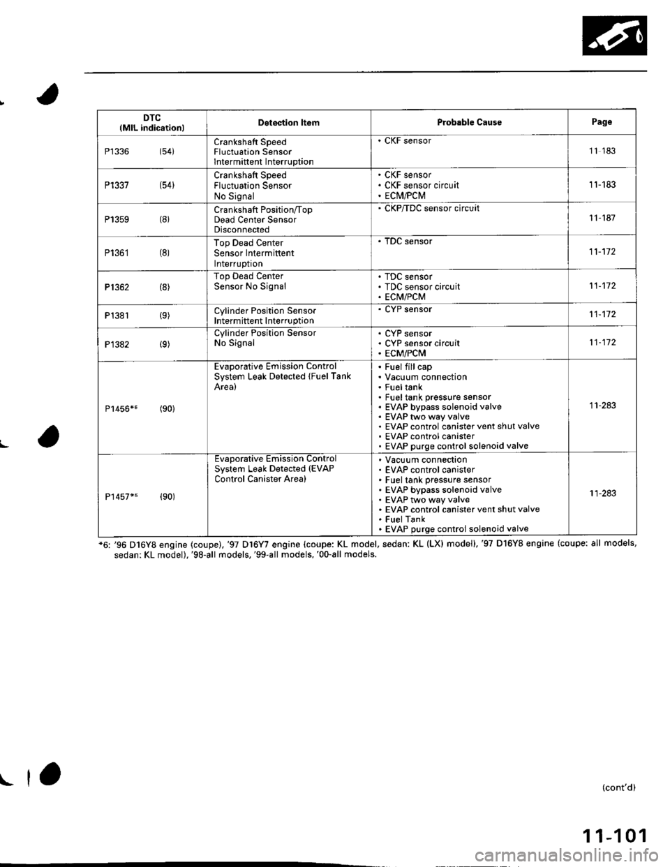
DTC(MlL indicationlDetection ltemProbable CausePage
P1336(54iCrankshaft SpeedFluctuation SensorIntermittent Interruption
. CKF sensor11 183
P1337 (54)Crankshaft SpeedFluctuation SensorNo Signal
CKF sensorCKF sensor circuitECM,PCM
11-'183
P13s9 (8)Crankshaft Position/TopDead Center SensorDisconnected
' CKP/TDC sensor circuit11-187
P1361 (8)Top Dead CenterSensor IntermittentInterruptron
. tuL sensor
11-172
P1362 (8)Top Dead CenterSensor No SignalTDC sensorTDC sensor circuitECIV/PCM
11-172
P1381 {9)Cylinder Position SensorIntermittent Interruption
. CYP sensor11-172
P1382 (9)Cylinder Position SensorNo SignalCYP sensorCYP sensor circuitECM/PCM
11-112
P1456*5(90)
Evaporative Emission ControlSystem Leak Detected {FuelTankArea)
FuelfillcapVacuum connectionFu€ltankFuel tank pressure sensorEVAP bypass solenoid valveEVAP two way valveEVAP control canister vent shut valveEVAP control canisterEVAP purge control solenoid valve
11-283
P1457*6 (90)
Evaporative Emission ControlSystem Leak Detected (EVAP
Control Canister Area)
Vacuum connectionEVAP control canisterFuel tank pressure sensorEVAP bypass solenoid valveEVAP two way valveEVAP control canister vent shut valveFuel TankEVAP purge control solenoid valve
11-283
L
*6: '96 D16Y8 engine (coupe),'97 Dl6Y7 engine (coupe: KL model, sedan: KL (LXl model),'97 D16Y8 engine (coupe: all models,
sedan: KL model),'98-all models,'99-all models,'00-all models.
(cont'd)
1 1-1 01
I ta
Page 372 of 2189
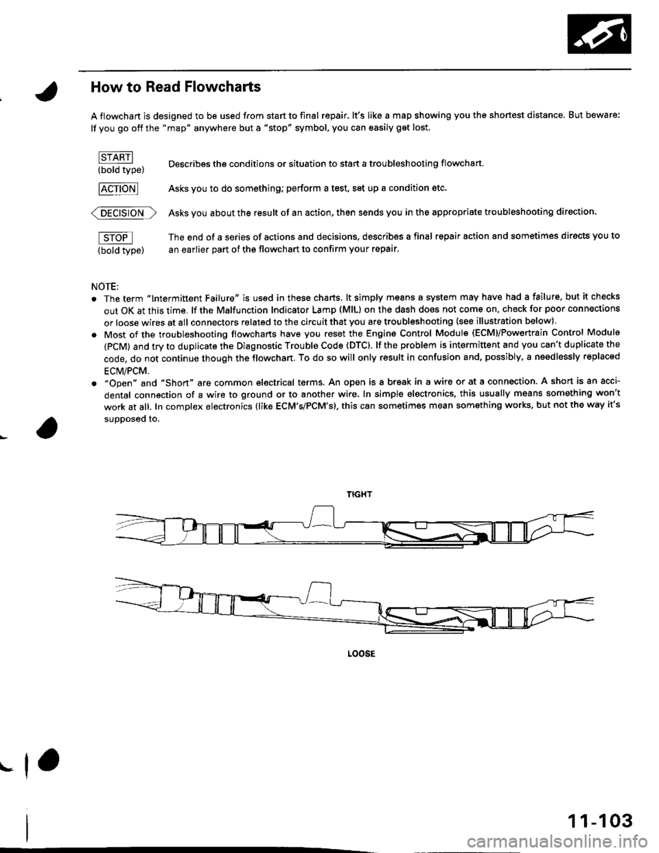
How to Read Flowcharts
A flowchart is designed to be used from start to final repair. lt's like a map showing you the shortest distance. But beware:
lf you go off the "map" anywhere but a "stop" symbol, you can easily get lost.
tSrARTl(bold type)
FanoNl
@
tsroP I
{bold type)
Describes the conditions or situation to start a troubleshooting flowchart.
Asks you to do something; perform a test, set up a condition etc.
Asks you about the result of an action, then sends you in the appropriate troubleshooting direction.
The end of a series of actions and decisions. describes a final repair action and sometimes directs you to
an earlier part of the flowchart to confirm your repair,
NOTE:
. The term "lntermittent Failure" is used in these charts, lt simply means a system may have had a failure. but it checks
out OK at this time. lf the Malfunction Indicator Lamp (MlL) on the dash does not come on, check for poor connections
or loose wires at all connectors related to the circuit that you are troubleshooting (see illustration below)'
. Most of the troubleshooting flowcharts have you reset the Engine Control Moduls (ECM)/Powertrain Control Module
(pCM) and try to duplicate the Diagnostic Trouble Code (DTC). lf the problem is intermittent and you can't duplicate the
code, do not continue though the flowchart. To do so will only result in confusion and, possibly, a needlessly replaced
ECM/PCM.
. ,,Open" and "Short" are common electrical terms. An open is a break in a wire or at a connection. A short is an acci-
dental connection of a wire to ground or to another wire. In simple electronics, this usually means something won't
work at all. In complex electronics (like ECM's/PCM'sl. this can sometim€s mean something works, but not the way it's
suDDosed to.
toosE
1 1-103
Page 376 of 2189
I
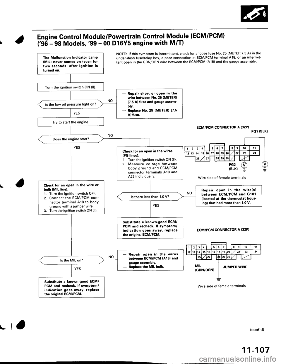
Engine Control Module/Powertrain Control Module (ECM/PCM)
t'96 - 98 Models,'99 - 00 Dl6Y5 engine with M/Tl
L
NOTE: lf th is svmptom is intermittent, check for a loose fuse No. 25 {METER 7.5 A) in the
underdash {use/relay box, a poor connection at ECM/PCM terminal A18, or an intermit
tent ooen in the GRN/ORN wire between the ECM/PCM (A18) and the gauge assemblv.
ECM/PCM CONNECTOR A I32PIPGl {BLKI
Wire side ot female terminals
ECM/PCM CONNECTOR A (32P}
Wire side of female terminals
(cont'd)
11-107
The Malfunc{ion Indicator Lamp
{MlLl never comes on (even lor
two secondsl atter ignition is
turned on.
Turn the ignition switch ON (ll).
- Repair short or open in thewile botwoen No. 25 {M€TERI
17,5 Altus€ and gau99 assem'
bty.- Replaco No.25 IMETERI (7,5
A)tuse.
ls the low oil pressure light on?
Try to start the engine.
Does the engine stan?
Check lor an open in the wiles
{PG linosl:1. Turn the ignition switch ON (ll).
2. ldeasure vo ltage betweenbody ground and ECM/PCMconnector terminals A10 andA23 individually.
Check tor an open in the wire ot
bulb (MlL line):1. Turn the ignition switch OFF.
2. Connect the ECM/PCM con-nector terminal A'18 to bodyground with a jumper wire.3. Turn the ignition switch ON (ll).
Repair open in the wire(s)
between ECM/PCM and G101(localod at the thetmostat hous_ingl that had more than 1.0 V.
ls thore less than 1.0 V?
Substituto . known-good ECM/PCM and recheck. It symptom/indication go6s away, roPlace
the origin.l ECM/PCM.
- Repair open in th€ wiresbetwoen ECM/PCM lAl8l andgaug6 a$embly.- Replace the MIL bulb,
ls the MIL on?
Substitute a known-good ECM/
PCM and .echeck. lf symptom/indication goes away, replacothe origin.l ECM/PCM.
268l011
12l3t5t61tIt192022232a
2527xt30
MrL I luanpen wrnrIGRN/ORN) I
!1,
Page 379 of 2189
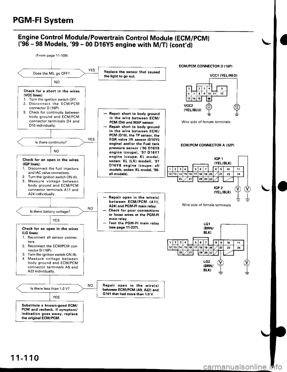
PGM-FI System
(From page 11-109)
Replace the sensor that causedthe light to go out.Does the N4lL go OFF?
Check fo. a short in the wi.os(VCC lines):':. Turn the ignition switch OFF.2. Disco n n ect the ECM/PCMconnector D (16P).
3. Check for continuity betweenbody ground and ECM/PCMconnector terminals D4 andD10 individually.
Ropair short to body groundin the wire betweon ECM/PCM {O4) and MAP s6n3or.Repair short to body groundin the wire between ECM/PCM lD10l, the TP sensor, theEGR valve lift sensor {D16Y5engine) and/or the Fuel tankpressure sensor {'96 Dl6Ygengine lcoupe),'97 D16Y7engine (coupe: KL model,sedan: KL (LXl model), '97
D16Y8 engine (coupe: allmodels, sedan: KL model. €8-allmodelsl.
ls there continuity?
Check tor rn open in the wires(lGP lines):1. Disconnect the fuel injectorsand IAC valve connectors,2. Turn the ignition switch ON (ll).3. Meas u re voltage betweenbody ground and ECM/PCMconnector terminals A11 and424 indivjdually.- Repair open in the wirels)between ECM/PCM (A11,A24land PGM-Fl main relay.- Check for poor connectionsor loose wiras at the PGM-FImain relay,- Test the PGM-FI mdin relavlsee pag6 11-237).
ls there battery vohage?
Check for an open in the wires(LG line3):1. Reconnect all sensor connectors.2. Reconnect the ECM/PCM con-nector D (16P).
3. Turn the ignition switch ON (ll).4. Measure vo ltage betweenbody ground and ECM/PCMconnector terminals Ag andA22 individually.
Repair open in the wirolglb€twe€n ECM/PCM {A9, A22} andG101 that had more than 1.0 V.
ls there less than 1.0 V?
Substitute 6 known-good ECM/PCM and r€check. lf symptom/indication 9o€s away, replacethe original ECM/PCM.
Engine Control Module/Powertrain Control Module (ECM/pCMl
('96 - 98 Models, '99 - 00 D16Y5 engine with M/Tl (cont,dl
ECM/PCM CONNECTOR D {16P}
Wire side of female terminals
ECM/PCM CONNECTOR A (32P}
Wire side of female terminals
11-110
LG1
VCCl {YEL/RED}
IGP 1{YEL/BLKI
2I11
1213l5t6Itt8t9202321
25272a2930
IGP 2(YEL/BLKIv) (l
{8RN/BLK)
I258tol1'12tt11t5l617t8t920232a
2A2330
LG2{8RN/8LK}
Page 381 of 2189
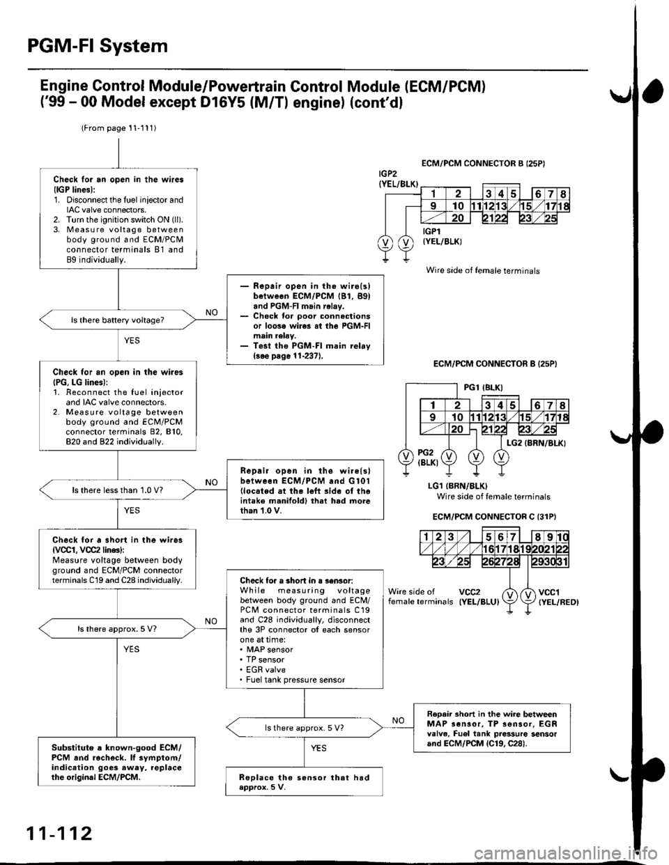
PGM-FI System
(From page'11-111)
Check loi an open in the wires(lGP linesl:1. Disconnect the lueliniector andIAC valve connectors.2. Turn the ignition switch ON (ll).
3, Measu re voltage betweenbody ground and ECM/PCMconnector terminals 81 andBg individually.
- Repair open in the wiro(3)between ECM/PCM lBl, B9land PGM-Fl main relay.- Check tor poor connectionsor loose wires al the PGM-FImain relav.- Test tho PGM-FI main rehy(3.e page 11-237).
ls there battery voltage?
Check tor an open in the wires(PG, LG lines):1. Reconnect the fuel iniectorand IAC valve connectors.2. Measure voltage betweenbody ground and ECM/PCMconnector terminals 82, 810,820 and 822 individually.
Repair open in the wirels)between ECM/PCM and G 101llocated ai the l6ft side of thointaks m.nifoldl thrt h.d morethan 1.0 V.
ls there lessthan 1.0 V?
Check for a short in the wires
{VCCI, VCC2 lin6s}:Measure voltage between bodyground and ECM/PCM connectorterminals C19 and C28 individually.Check toa a 3hort in s 3ensor:While measuring voltagebetween body ground and ECM/PC[/t connector terminals C19and C28 individually, disconnectthe 3P connector of each sensorone at time:. MAP sensor. TP sensor. EGR valve. Fueltank pressure sensor
ls there approx.5 V?
Reoair short in lhe wire betwe.enMAP 3ansor, TP sensor, EGRvalve, Fuel tank pres3ure 3ensorand ECM/PCM {Cl9, C28).
ls there approx. 5 V?
Substiiute a known-good ECM/PCM and racheck. ll symptom/indicetion goes eway, replaceth6 original ECM/PCM.Replace tho sansor that had.pprox. 5 V.
Engine Control Module/Powertrain
('99 - 00 Model except Dl6Y5 (M/Tl
Module (ECM/PCM)
(cont'd)
Control
engine)
ECM/PCM CONNECTOR B {25P)
LG1 (BRN/BLKI
Wire side of female terminals
ECM/PCM CONNECTOR C (31P)
female terminalsvcc2IYEL/BLUIvccl{YEL/RED)
Wire side of female terminals
11-112