connection HONDA CIVIC 1999 6.G Repair Manual
[x] Cancel search | Manufacturer: HONDA, Model Year: 1999, Model line: CIVIC, Model: HONDA CIVIC 1999 6.GPages: 2189, PDF Size: 69.39 MB
Page 1392 of 2189
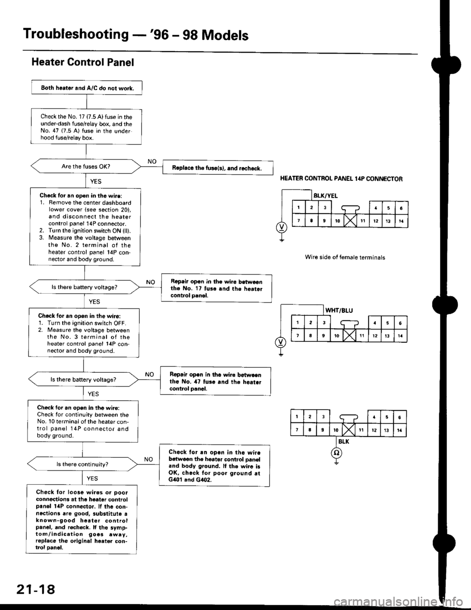
Troubleshooting -'96 - 98 Models
Both heater and A/C do not work.
Check the No. 17 {7.5 A) fuse in theunderdash fuse/relay box, and theNo. 47 (7.5 A) fuse in the underhood fuse/relay box.
R.phce the fuso{s), .nd rccheck.
Chack tor an open in the wi.e:1. Remove the center dashboardlower cover (see section 20),and disconnect the heatercontrol panel 14P connector.2. Torn the ignition switch ON {ll).3. Measure the voltage betweenthe No. 2 terminal of theheater control panel 14P con-nector and body ground.
Rcpair opGn in th€ wiro betwoonthe No. 17 tuse and the hoatclcontrol panel.
ls there baftery voltage?
Check for an opon in the wiro:1. Turn the ignition switch OFF.2. Measure the voitage betweenthe No. 3 terminal of theheater control panel 14P con-nector and body ground.
Rgprii open in th6 wira b€twacnthe No. il7 tui. and the heat.tcont.ol p.nal.
ls there battery voltage?
Check foi an open in the wi.e:Check for continuity between theNo. 10 terminal ot the heater con-trol panel 14P connector andbody ground.
Check lor an opon in tho wireb€{w6on the hoator control oaneland body ground. lI the wirc isOK, check tor poor ground atG401 .nd G4O2.
Check for looae wiaos or ooolconnections at the hoater controlpanol 14P connector. lf the con-nactions dre good. 3ubstitute tknown-9ood heater controlpanel, and rech6ck. It tho symp-tom/indication 9oe3 .wry,replace the original heatel con-trol oanol.
Heater Control Panel
HEATER CONTROL PANEL 1,lP CONNECTOR
Wire side of female terminals
21-18
Page 1396 of 2189
Troubleshooting -'gg - 00 Models
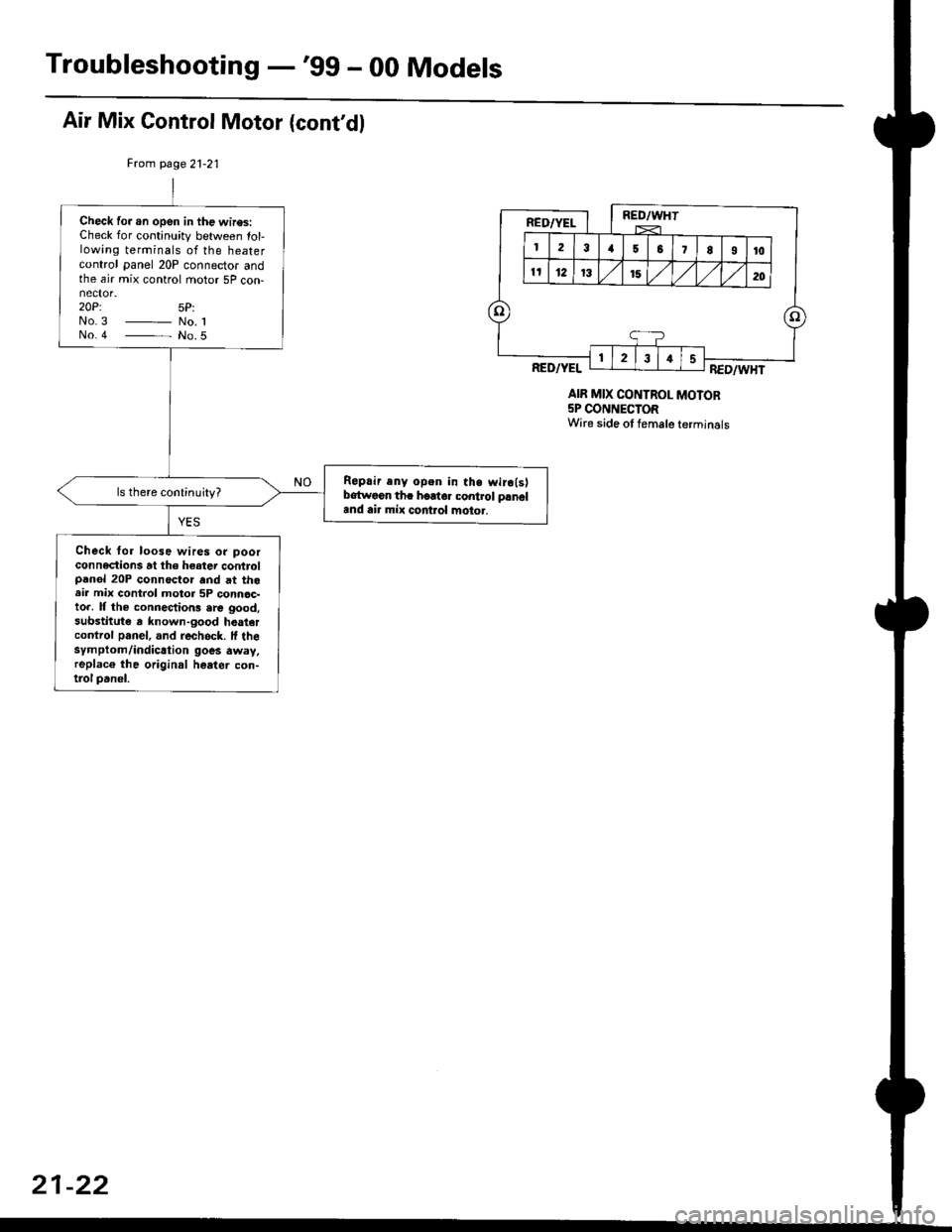
Air Mix Control Motor (cont'dl
Frcm page21-21
AIR MIX CONTROL MOTOR5P CONNECTORWire side ot female terminals
Check fo..n open in the wires:Check for continuity between lol-lowing terminals of the heatercontrol panel 20P connector andthe air mix control motor 5P con-
20P: 5P:No3 _ No. 1No.4 - No.5
Repair any open in the wiro(s)bdtwoon tha hoator control panaland air mix control motor.
Check for loo3e wires or poorconneclions at the heater controlpanol 20P connoctor and at theair mix control motor 5P connoc-to.. It the connections .rc good,substitute a known-good hoaiercontrol panel, and rech6ck. lf thesymptom/indicrtion goes away,replac6 the original heater con-trol panel.
21-22
Page 1398 of 2189
Troubleshooting -'99 - 00 Models
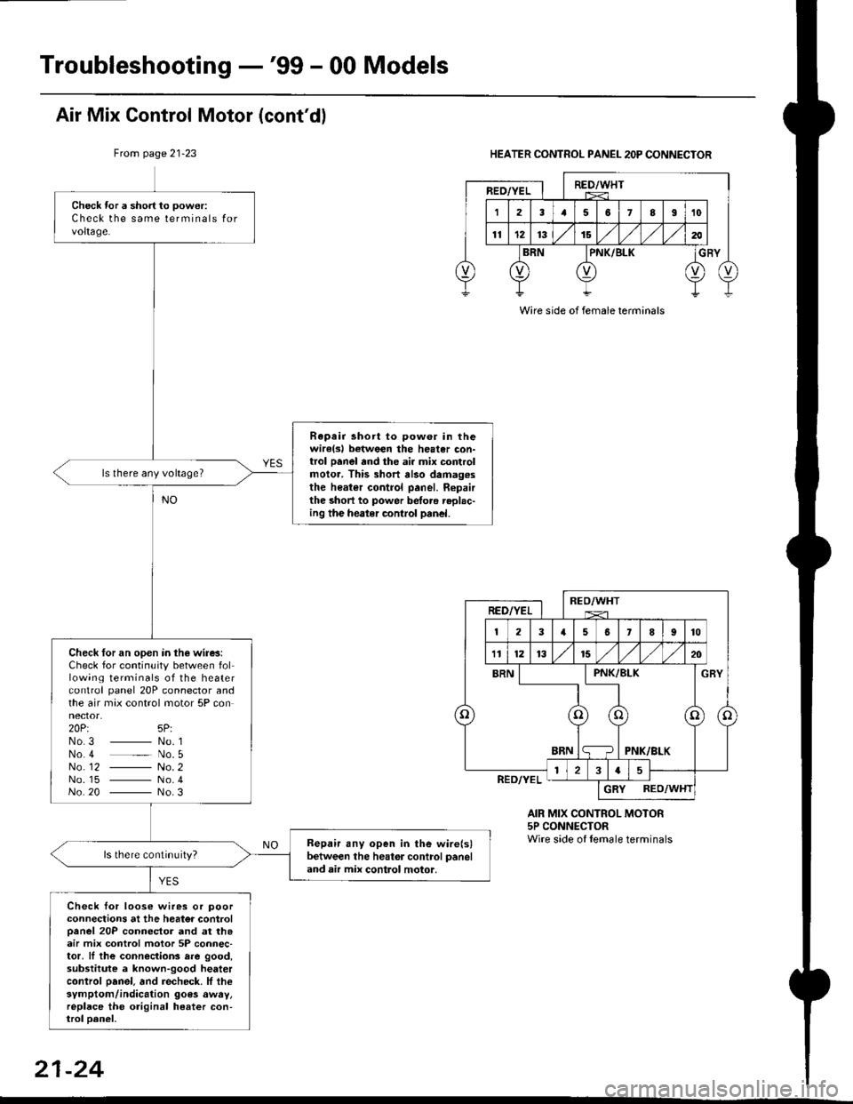
Check tor a short to power:
Check the same terminals forvoltage.
Rapair short to pow6r in thewirelsl botween the heater con-trol panel and the ai. mix controlmolor. This short also damag.sthe heater control panel. Ropairthe short to power betoro replac-ing the heater control panel.
ls there any voltage?
Check for an open in the wire3:Check for continuity between following terminals of the heatercontrol panel 20P connector andthe air max control motor 5P connector.20Pt 5P:No3 _ No. 1No 4 _ No. 5No_ 12 - No. 2No. 15 - No.4No 20 - No.3
Bepair any open in the wire(s)between the heator control paneland air mix control motor,
Check tor loose wires or poorconnections at the heator controloanel 20P connector and at th.air mix control motor 5P connec-tor, ll the connections rre good,substitute a known-good heatercontrol oanel. and recheck. lf thesymptom/indication goes awry,replace the original heater con-trol oanel,
Air Mix Control Motor (cont'dl
From page 21-23HEATER CONTROL PANEL 2OP CONNECTOR
AIR MIX CONTROL MOTOR5P CONNECTORWire side of lemale terminals
Wire side of female terminals
21-24
Page 1400 of 2189
Troubleshooting -'gg - 00 Models
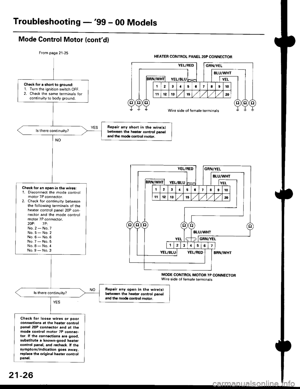
Mode Gontrol Motor (cont'dl
From page 21-25
MODE CONTROL MOTOR ?P CONNECTORWire sade of lemale terminals
Chock tor a short to ground:1. Turn the ignition switch OFF.2. Check the same terminals forcontinuity to body ground.
Repair any 3hort in the wirelslbetween the heater control paneland ihe mode control motor.
ls there continuity?
Check lor.n open in tho wires:1, Disconnect the mode controlmotor 7P connector.2. Check for continuity betweenthe following terminals of theheater control panel 20P connector and the mode controlmotor 7P connector.2OP: lPiNo.2 - No.7No.5- No.2No.6- No.6No.7 - No.5No.8- No.4No.I - No.3
Repair any opon in the wire(s)t€tween the h€ater control paneland tha modc contol motor.
ls there continuity?
Check for loose wiaes or ooorconnections at the heater controlpanel 20P connector rnd at themode control motor 7P connec-toa, lf the connoctions ere good,substitute a known-good heatercontrol panol, and recheck. lf thesyfiptom/indication goes away,replac€ the original hoater controlpanel.
HEATER CONTROL PANEL 2OP CONNECTOR
Wire side of female terminals
21-26
Page 1402 of 2189
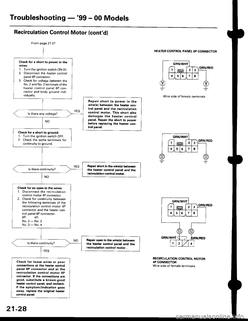
Troubleshooting -'99 - 00 Models
Recirculation Control Motor (cont'd)
Frcm page 21-27
HEATER CONTROL PANEL 8P CONNECTOR
Check for a short to power in the
1. Turn the ignition switch ON {ll).2. Disconnect the heater controlpanel 8P connector.3. Check for voltage between theNo.2 and No. 3 terminals oftheheater control panel 8P con,nector and body ground individually.
Repair 3hort to powe. in thewire{a) b.tween tho haetor con-trol panel and the recirculationGontrol moto.. This short alsodamagos the heate. controlpanel. Repair the short to powerb€tore .eplecing the h€ater con-trol panel.
ls there any voltage?
Check to. a short to ground:1. Turn the ignition switch OFF.2- Check the same terminals forcontinuity to ground.
Roprir lhon in tho wir.{s) b€tweothe horter control panel and theracircr alion conhol motoa.
Check for an open in the wires:1. Disconnect the recirculationcontrol motor 4P connector.2. Check for continuity betweenthe following terminals of therecirculation control motor 4Pconnector and the heater con,trol panel 8P connector.8P: 4PiNo.2 - No.2No.3 - No.4
Repair open in ths wirolsl betw€€nthe heate. co.rkol panol and therecirculation control motor .
Check lor loo3a wires or pootconn€ctions at the hoater controlpanel 8P connector and at theaecirculation control motor ilPconnector, It tho connections aregood. substitut€ e known-goodheatei control panel, and aecheck.lf th€ symptom/indication goesaway, replace the original hedtercontrcl Danel.
GRN/WHT
I1
GRN/RED
RECIRCULATION CONTROL MOTOR4P CONNECTORWire side of female terminals
21-28
Page 1404 of 2189
Troubleshooting -'99 - 00 Models
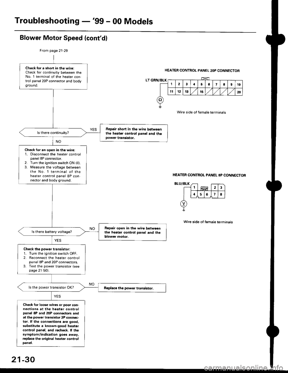
Blower Motor Speed (cont'dl
HEATER CONTROL PANEL 2OP CONNECTOR
Wire side oJ female terminals
Wire side ot female terminals
Frcm page 21.29
LT GRN/BLK
Check tor a short in the wi.a:Check for continuity between theNo. 1 terminal of the heater control panel 20P connector and bodyground.
Repair short in ths wire betwsenthe hoater control panel and theoower transastoa.
Check for an open in the wire:1. Disconnect the heater controlpanel 8P connector,2. Turn the ignjtion switch ON 1ll).3. Measure the voltage betweenthe No. 'l terminal of theheater control panel 8P connector and body ground.
Repeir open in the wiio betweenthe heater control panel and theblower motoa.
Check the power transistor:1. Turn the ignition switch OFF.2. Reconnect the heater controlpanel 8P and 20P connectors.3. Test the power transistor {seepage 21 50).
ls the power transistor OK?
Check for loos€ wiras or poor con-nections at the h€at€r controlpanel 8P and 20P connectols andat th6 power transistor 3P conn€c-tor. lf the connections are good,substituto a known-good hoatercontrol panel, and recheck. It thesymptom/indication goes away,replace the original heater controloanel,
HEATER CONTNOL PANEL 8P CONNECTOR
21-30
Page 1409 of 2189
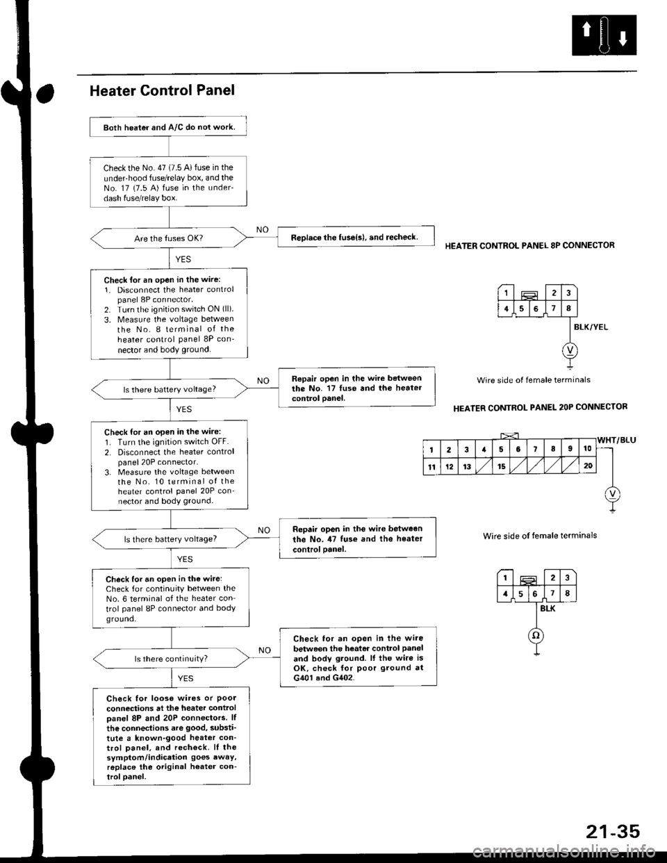
Both heater and A/C do nol work.
checkthe No.47 (7.5 A)fuse in the
under-hood fuse/relay box, and theNo. 17 {7.5 A) fuse in the under-
dash fuse/relay box.
ReDlace the tuse{s), and recheck.
Check lor an open in the wire:
1. Disconnect the heater controlpanel 8P connector,2. Turn the ignition switch ON (ll).
3. Measure the voltage between
the No. I terminal of the
heater control panel 8P con-
nector and body ground.
Repair open in the wire betweenthe No. '17 luse and th6 heatercontrol oanel,ls there battery voltage?
Check for an open in the wire:
1. Turn the ignition switch OFF.
2. Disconnect the heater controlpanel20P connector.3. Measure the voltage lletweenthe No. 10 terminal of theheater control Panel 20P con-nector and body ground.
Repair op6n in the wir€ between
the No. il7 tuse and the heater
controloanel,ls there battery voltage?
Check for an open in the wite:Check for continuity between theNo. 6 terminal of the heater con
trol panel 8P connector and bodyground.
Ch6ck tor an open in lhe wire
betwoen the heator control Paneland bodv ground. lf the wire isOK, check for poor ground atG401 and G402.
ls there continuity?
Check for looso wires or Poolconneciions at the heater controloanel 8P and 20P connectors. lf
the connections are good, substi'
tute a known-good heat€r con-trol Danel, and recheck. lI thesymptom/indication goes awaY,r6place the original h€ater con-troloanel.
HEATER CONTROL PANEL 8P CONNECTOR
BLK/YEL
Wire side of female terminals
HEATER CONTROL PANEL 2OP CONNECTOR
Wire side of temale terminals
I2
1578
BLK
o
1
4I
v
Page 1420 of 2189
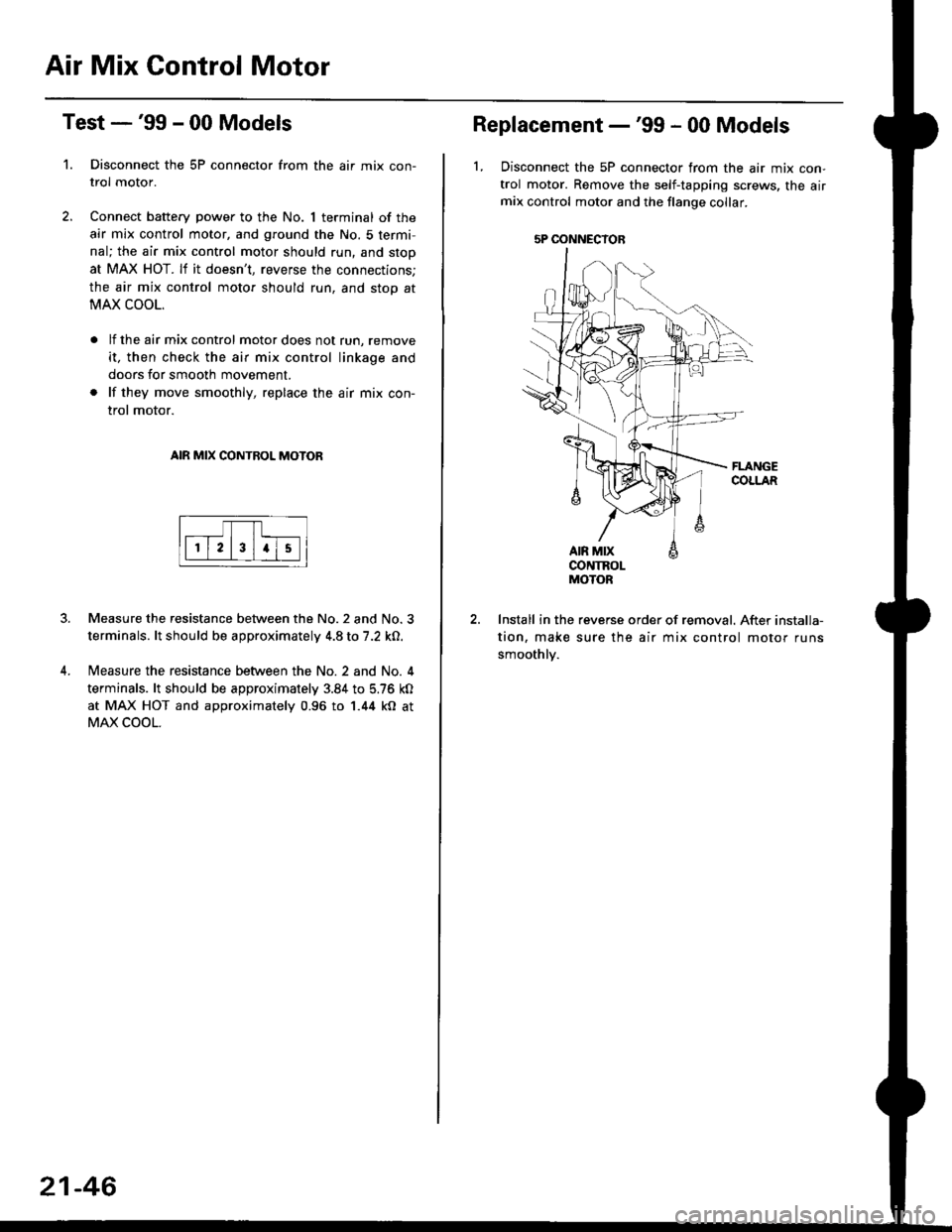
Air Mix Gontrol Motor
't.
Test -'99 - 00 Models
Disconnect the 5P connector from the air mix con-
trol motor.
Connect battery power to the No. 1 terminal of the
air mix control motor, and ground the No. 5 termi,
nal; the air mix control motor should run, and stop
at MAX HOT. lf it doesn't, reverse the connections;
the air mix control motor should run, and stop at
MAX COOL.
lf the air mix control motor does not run, remove
it, then check the air mix control linkage and
doors for smooth movement.
lf they move smoothly, replace the air mix con-
trol motor.
AIR MIX CONTROL MOTOR
Measure the resistance between the No.2 and No.3
terminals. lt should be approximately 4.8 to 7.2 kO.
Measure the resistance between the No. 2 and No. 4
terminals. lt should be approximately 3.84 to 5.76 kO
at MAX HOT and approximately 0.96 to 1.44 kO at
MAX COOL.
21-46
5P OONNECYOB
Replacement -'99 - 00 Models
1, Disconnect the 5P connector from the air mix con-
trol motor. Remove the self-tapping screws, the airmix control motor and the flange collar.
CONTROLMOTOR
Install in the reverse order of removal. After installa-
tion, make sure the air mix control motor runs
smoothly.
Page 1421 of 2189
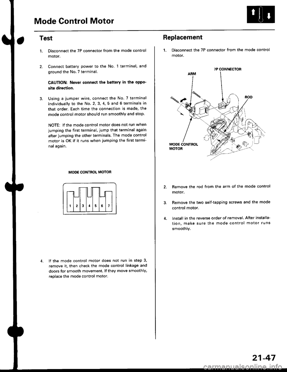
Mode Control Motor
2.
Test
1.
4.
Disconnect the 7P connector from the mode control
motor.
Connect battery power to the No, 1 terminal, and
ground the No.7 terminal,
CAUTION: Never connecl the battery in iho oppo-
site direction.
Using a jumper wire, connect the No. 7 terminal
individually to the No. 2,3, 4,5 and 6 terminals in
that order. Each time the connection is made, the
mode control motor should run smoothly and stop.
NOTE: lf the mode control motor does not run when
jumping the first terminal, jump that terminal again
after jumping the other terminals. The mode control
motor is OK if it runs when jumping the first termi-
nal again.
MODE CONTROL MOTOR
lf the mode control motor does not run in step 3,
remove it. then check the mode control linkage and
doors for smooth movement. lf they move smoothly,
reolace the mode control motor,
Replacement
1. Disconnect the 7P connector from the mode control
motor,
Remove the rod from the arm of the mode control
motor.
Remove the tyvo self-tapping screws and the mode
control motor.
lnstall in the reverse order of removal. After installa'
tion, make sure the mode control motor runs
smoothly.
7P CONNECTOR
21-47
Page 1440 of 2189
Troubleshooting
Gompressor (cont'dl
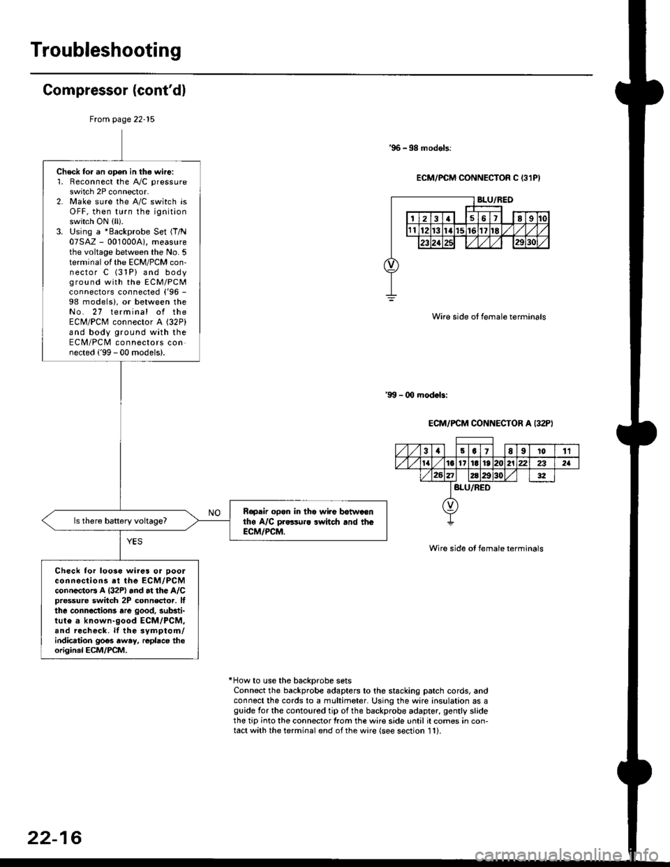
'96 -98 models:
ECM/PCM CONNECTOR C 13lPI
Wire side ot female terminals
'9!t - 00 mod.bi
ECM/PCM CONNECTOR A I32P)
Wire side ot female terminals
*How to use the backprobe setsConnect the backprobe adapters to the stacking patch cords, andconnect the cords to a multimeter. Using the wire insulation as aguide for the contoured tip of the backprobe adapter, gently slidethe tip into the connector from the wire side until it comes in con-tact with the terminal end ofthe wire {see section 11}.
From page 22-15
Check for an open in thg wire:'1. Reconnect the A"/C pressure
switch 2P connector.2. Make sure the A/C switch isOFF, then turn the ignitionswitch ON (ll).
3. Using a *Backprobe Set {T/N07SAZ - 001000A), measurethe voltage between the No. 5terminal of the ECM/PCM con-nector C (31P) and bodyground with the EcM/PcMconnectors connected ('96 -
98 models), or between theNo. 27 terminal of theECM/PCM connector A (32P)
and body ground with theECM/PCM connectors connected ('99 - 00 models).
Rapdir open in tho wi?e botwaonthe A/C pr..-ruro lwitch rnd th.ECM/PCM.
Check lor loo3e wires or ooolconnections at the ECM/PCMconnectoB A l32P) and at the A/Cpressure switch 2P connector, lfthe connections are good, substi-tute a known-good ECM/PCM,and recheck. lf the svmptom/indication goos away, repbce theoriginal ECM/PCM.
31501E91011
tat6l11E1921222321
BLU/RED
22-16