engine HONDA CIVIC 1999 6.G Workshop Manual
[x] Cancel search | Manufacturer: HONDA, Model Year: 1999, Model line: CIVIC, Model: HONDA CIVIC 1999 6.GPages: 2189, PDF Size: 69.39 MB
Page 533 of 2189
Emission Gontrol System
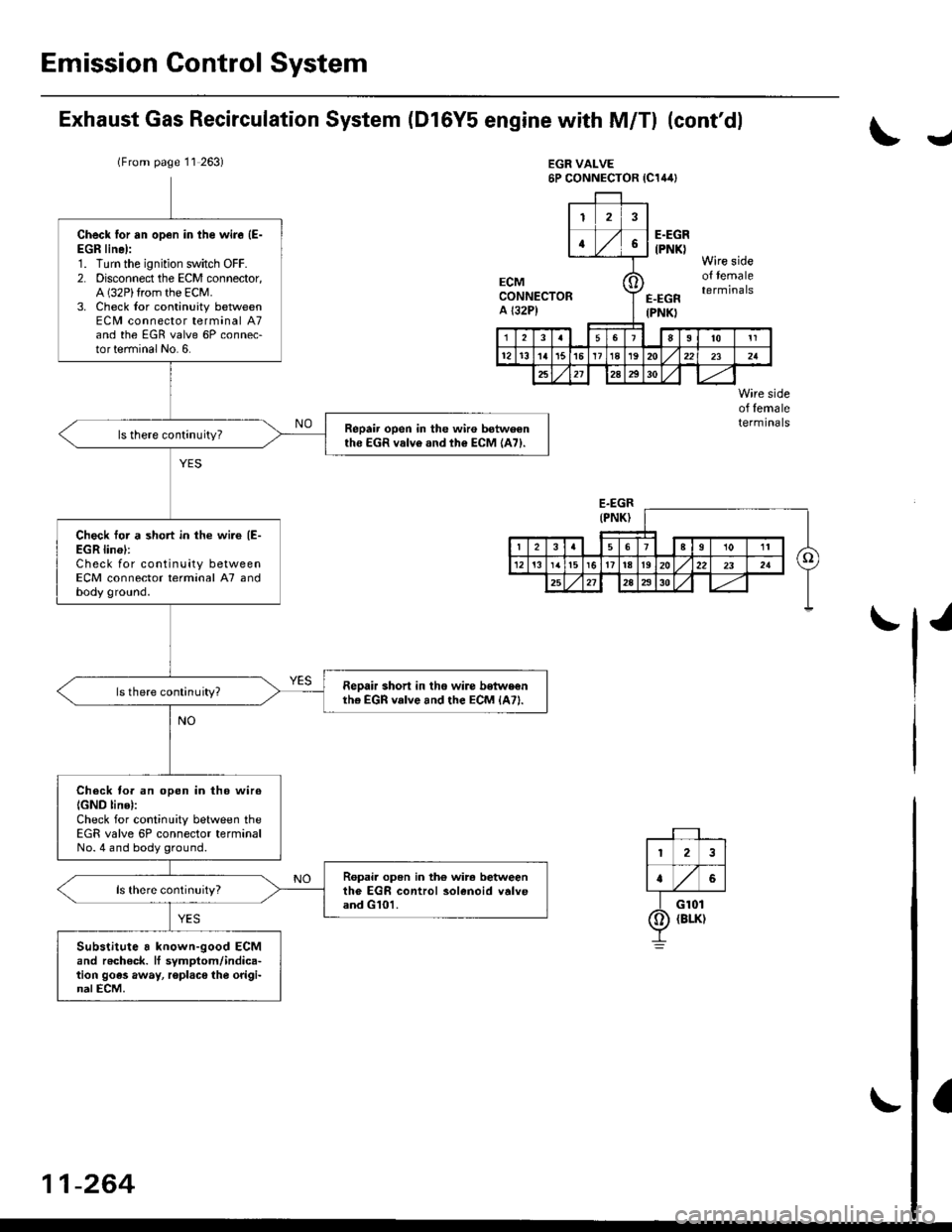
Exhaust Gas Recirculation System (Dl6Y5 engine with M/Tl (cont'dl
lFrom page 11 263)EGR VALVE6P CONNECTOR {C144}
J
Wire sideof femaletermtnals
J
Check lor an op€n in the wire (E-
EGR line):1. Turn the ignition switch OFF.2. Disconnect the ECM connector,A (32P)trom the ECM.3. Check lor continuity betweenECM connector terminal A7and the EGR valve 6P connec-torterminal No. 6.
Repair open in the wiro botweenthe EGR valv6.nd th€ ECM {A71.
Check tor a short in the wire {E-EGR lin6l:Check for continuity betweenECM connector terminal A7 andbody ground.
Reoair shorl in tho wiro belwe€nthe EGn vake rnd the ECM lA7l.ls there continuity?
Check fo. an open in tho wiro
IGND line):Check for continuity between theEGR valve 6P connector terminalNo.4 and body ground.
R6pai. open in th€ wir. betweenth6 EGF control solenoid v6lveand G101.
Substitute 8 known-good ECMand recheck. It symptom/indica-tion goes away, roplace the origi-nalECM.
CONNECTORA l32P)
2
a
I G101
Q) raur
-264
Page 534 of 2189
J\
Exhaust Gas Recirculation System
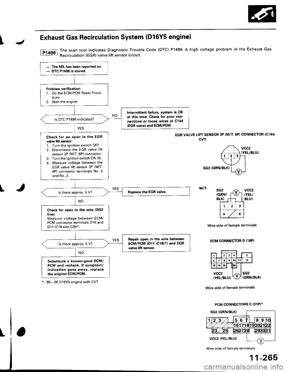
The scan tool indicates Diagnostic Trouble
Recirculation (EGRlvalve lift sensor circuit.
(D16Y5 enginel
Code {DTC) P1498: A high voltage problem in the Exhaust Gas
EGR VALVE LlFf SENSOR 3P {M/T: 6Pl CONNECTOR (C1441
cvT:
vcc2{YEL/BLUI
SG2 IGRN/BLK)
IM/T:sG2{GRN/BLKI
Wir€ side ol lemale terminals
ECM CONNECTOR D (16P)
vcc2(YEL/BLUIsG2(GRN/BLK)
Wir€ side of female terminals
PCM CONNECTORS C 131P)'
Wire side oI female terminals
11-265
- The MIL has been reportod on.- DTC P1498 is storod.
Probl€m verification:1. Do the ECM/PCM Reset Proce
dure.2. Stan the engine.
Intermittent tailure, sy3lem is OK
at lhis time. Check tor poor con'
nections or loose wire3 at C144
|EGR valvel and ECM/PCM.
ls DTC P1498 indicated?
Check for an open in tho EGRvalv6 lift sen3or:1. Turn the ignition switch OFF.
2. Disconnect the EGR valve lift
sensor 3P (M/T: 6Pl connector.
3. Turn the ignition switch ON (ll).
4. Measure voltage between the
EGR valve litt sensor 3P lM/T:6P) connector terminals No. 3and No.2.
ls there approx.5 V?
Check lor op€n in th€ wire (SG2
line):Measure voltage between ECM/PCM connector terminals 010 andD1l (C18 and C28)*.
Repair open in tho wiro betwoen
ECM/PCM lDl1 (Cl8)r) and EGR
valvo lift sensor.ls there approx. 5 V?
Substitute . known-good ECM/PCM and recheck. ll symptom/indicrtion goes away, replacothe original ECM/rcM.
*:'99 - 00 D16Y5 engine with CVT
Page 535 of 2189
Emission Control System
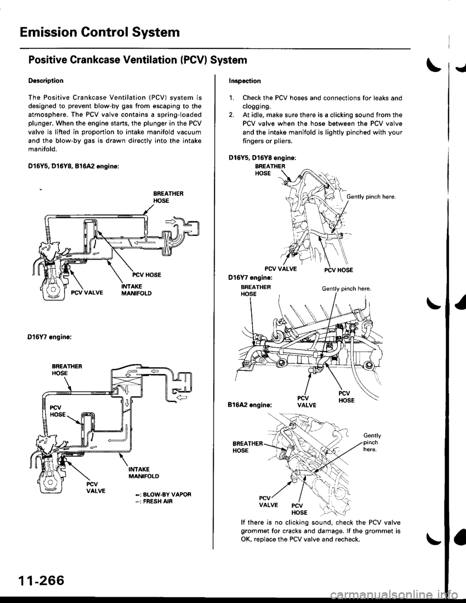
Positive Crankcase Ventilation IPCVI System
Descripiion
The Positive Crankcase Ventilation (PCV) system is
designed to prevent blow-by gas from escaping to the
atmosphere. The PCV valve contains a spring-loaded
plunger. When the engine starts, the plunger in the PCV
valve is lifted in proportion to intake manifold vacuum
and the blow-by gas is drawn directly into the intake
manifold.
D15Y5, D16Y8, 816A2 ongins:
BREATHERHOSE
Dl6'|11 6ngin6:
-: aLOW-BY VAPOR-: FnESH AIF
11-266
tJ
lrcpection
1. Check the PCV hoses and connections for leaks and
clogging.
2. At idle, make sure there is a clicking sound from the
PCV valve when the hose between the PCV valve
and the intake manifold is lightly pinched with your
fingers or pliers,
D16Y5, D16Y8 ongins:
BREATHERHOSE
PCV VALVE
Gently pinch here.
Bl6A2 engins:VALVE
lf there is no clicking sound, check the PCV valve
grommet for cracks and damage. If the grommet is
OK, replace the PCV valve and recheck.
PCV
Page 536 of 2189
1\
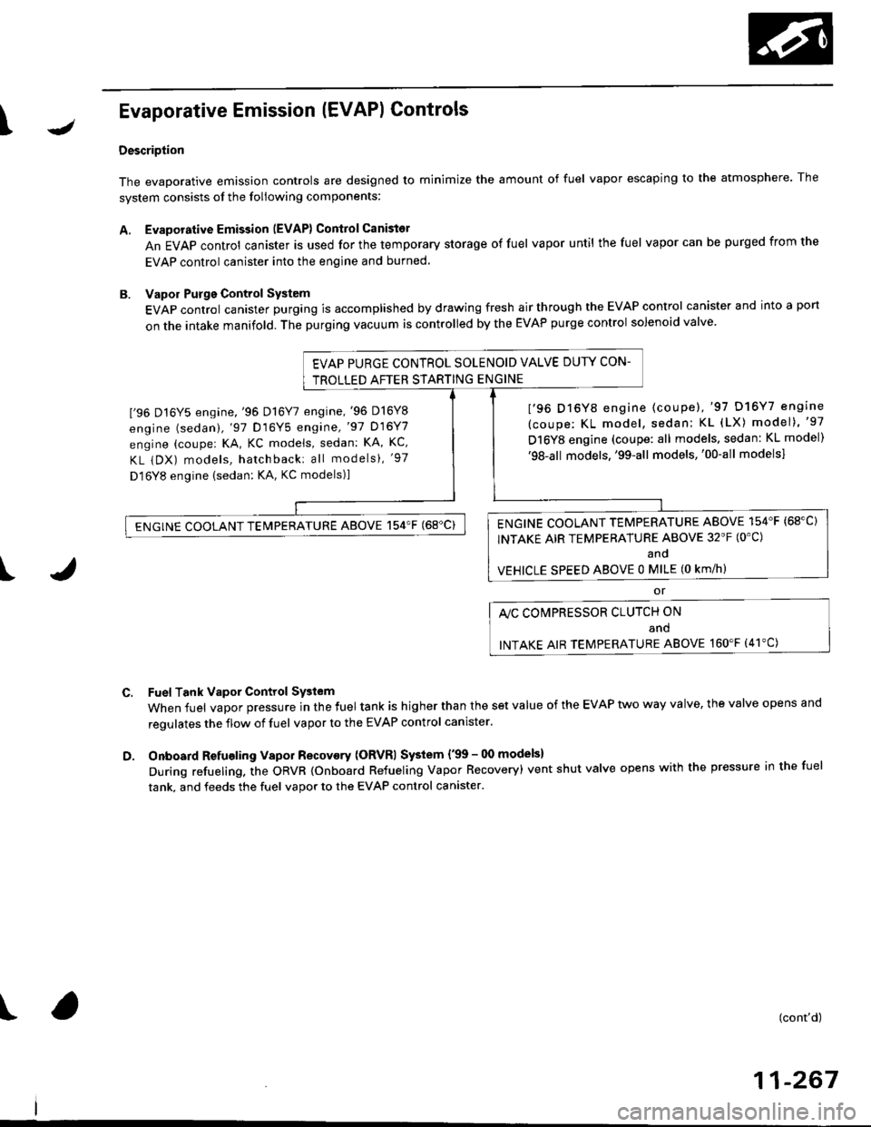
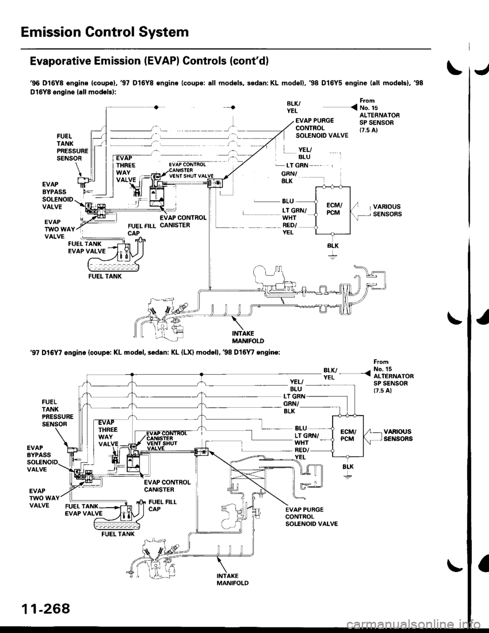
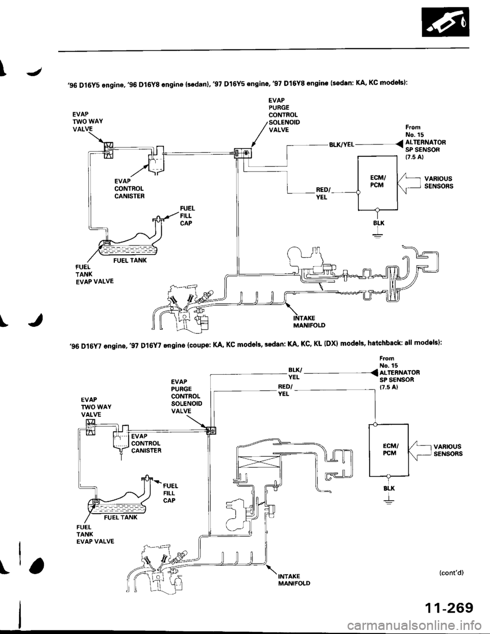
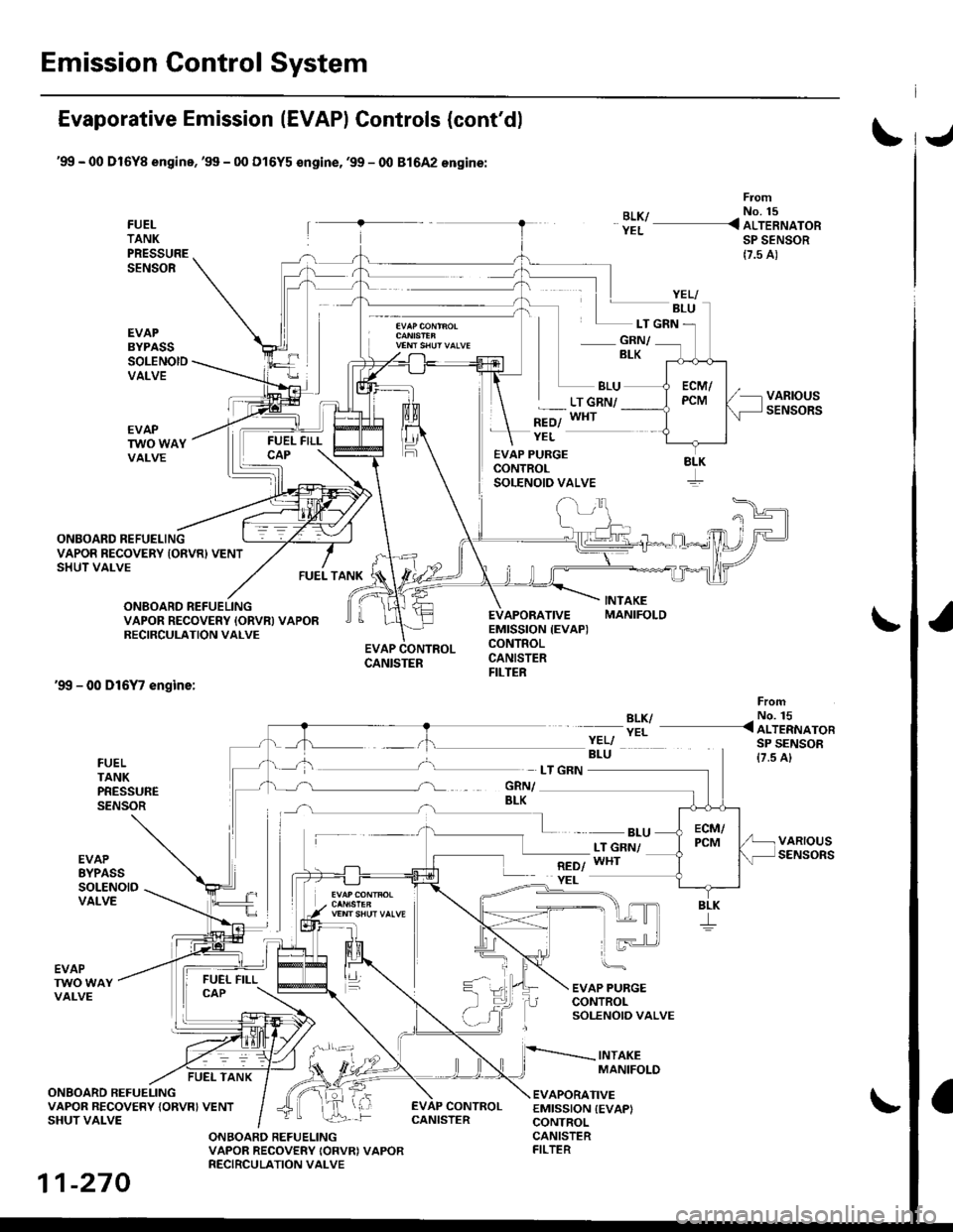
Evaporative Emission (EVAPI Controls
Description
The evaporative emission controls are designed to minimize the amount of fuel vapor escaping to the atmosphere. The
system consists of the foliowing components:
A. Evaporative Emission (EVAP) Control Canisto]
An EVAP control canister is used for the temporary storage of fuel vapor until the fuel vapor can be purged from the
EVAP control canister into the engine and burned.
B. Vapor Purge Control System
EVAP control canister purging is accomplished by drawing fresh air through the EVAP control canister and into a port
on the intake manifold. The purging vacuum is controlled by the EVAP purge control solenoid valve.
I'96 D16Y5 engine,'96 Dl6Y7 engine,'96 D16Y8
engine (sedan),'97 D16Y5 engine,'97 D16Y7
engine (couper KA, KC models, sedan: KA, Kc'
KL iDX) models, hatchback: all models), '97
D 16Y8 engine (sedan: KA, KC models)l
I'96 D16Y8 engine (coupe),'97 D16Y7 engine
(coupe: KL model, sedan: KL (LX) model)"97
D16Y8 engine (coupe: all models, sedan: KL model)'98-all models,'99-all models,'00-all modelsl
I
c.
D.
or
l'lc COMPRESSOR CLUTCH ON
and
INTAKE AIR TEMPERATURE ABOVE 160"F (41'C)
Fuel Tank Vapor Control System
When fuel vapor pressure in the fuel tank is higher than the set value of the EVAP two way valve, the valve opens and
regulates the flow of fuel vapor to the EVAP control canister.
Onboard Refueling Vapor Recovery (ORVRI System {'99 - 00 models}
During refueling. the oRVR {onboard Refueling Vapor Recovery) vent shut valve opens with the pressure in the fuel
tank. and feeds the fuel vapor to the EVAP control canister.
t(cont'd)
11-267
EVAP PURGE CONTROL SOLENOID VALVE DUTY CON-
TROLLED AFTER STARTING ENGINE
ENGINE COOLANT TEMPERATURE ABOVE 154'F {68"C)
INTAKE AIR TEMPERATURE ABOVE 32'F (O'C)
and
VEHICLE SPEED ABOVE O MILE (O KM/h}
ENGINE COOLANT TEMPERATURE ABOVE 154'F (68'C)
Page 537 of 2189
Emission Control System
Evaporative Emission IEVAPI Controls (cont'd)
'96 D16Y8 ongins (coupol.'97 D16Y8 €ngino (coups: all mod€ls, sedan: KL model),'98 D16Y5 engine (all mod6lsl,'98
Dl5YB engine {all modols):
{BLK/YEL
From
< No. 15
FUELTANKPRESSURESENSOR
EVAP PURG€CONTROLSOLENOID VALVE
.� LT GRN
GRN/BLK
ALTERNATORSP SENSOR(7.5 A)
VARIOUSSENSORS
YEL/BLU
V€NT SHUT
EVAPBYPASSSOLENOIDVALVEL BLU
WHTRED/YEL
L __ LT GRN/
EVAPTWO WAYVALVE
INTAKEMANIFOI.I'
'97 D16Y7 engin. (coupa: KL model, sedan: KL {LX) model},38 Dl6
/ engine:
?:y- -<
FromNo. 15ALTERNATORSP SENSOR17.5 A)
FUELTANKPRESSURESENSOR
YEL/BLULT G]GRN/BLK
LT GRN/WHT
BLU
YEL
EVAPBYPASSRED/
VALVE
EVAPTWO WAVALVE
EVAP CONTROLCANISTER
FUEL FILLCAP
BLK
11-268
FUEL TANK
Page 538 of 2189
J
'96 Dl6Y5 engine,'96 D16Y8 engine (sodanl,'97 Dl6Y5 sngino,'97 Dl6Y8 sngine (sedan: KA, KC modols):
EVAPTWO WAY
EVAPPURGECONYROLSOLENOIDVALVEVALFromNo. 15
BLK/YEL__ _ < ALTERNATOR- SP SENSOR
FUELFILLCAP
VARIOUSSENSORS
(cont'd)
11-269
I
'96 D16Y' engin.,.9? D16Y7 engine {coupe: KA, KC models, sedan: KA. KC, Kl- IDX) modols, hatchback: all models}:
FromNo. 15
3lI/- - - -{ ALTERNAT'RSP SENSORRED/YEL
EVAPPUBGECONTROLSOLENOIDVALVE
FUELFILLCAP
8LK
+
t\,"ro*,
MANIFOLD
Page 539 of 2189
Emission Control System
Evaporative Emission (EVAPI Controls (cont'd)
'99 - 00 Dl6Yg engine,'99 - 00 Dl6Y5 €ngine,'99 - 00 81642 engine:
FUELTANKPRESSURESENSOR
EVAPBYPASSSOLENOIDVALVE
From
BLK/ - No. 15
YEL _ ALTERNATORSP SENSOR
{7.5 A)
- GRN/BLK
BLU
*=ol
LT GRN/WHT
ONBOARD REFUELING
FUEL TANK
EVAP PURGECONTROLSOLENOID VALVE
EVAPORATIVEEMISSION {EVAP)CONTROLCANISTERFILTER
YEL
LT GRN
VAPOR RECOVERY IONVR) VENTSHUT VALVE
ONBOARD REFUELINGVAPOR RECOVERY IORVN} VAPORRECIRCULATION VALVE
'99 - 00 D16Y7 engine:
EVAP CONTROLCANISTER
BLK/YEL
FromNo. 15< ALTERNATORSP SENSOR{7.5 A}FUELTANKPRESSURESENSOR
EVAPEYPASSSOLENOIDVALVE
- BLULT GNN/WHT
EVAP PURGECONTROLSOLENOIO VALVE
INTAKEMANIFOLD
EVAPTWO WAYVALVE
FUEL TANK
ONBOARD REFUELINGVAPOR RECOVERY {ORVRI VENTSHUT VALVE
EVAPORATIVEEMISSION {EVAPICONTROL
EVAP CONTROL
ONBOARD REFUELINGVAPOR RECOVERY IORVRI VAPORRECIRCULATION VALVE
CANISTERFILTER
YELI
8LK
11-270
CANISTER
Page 540 of 2189
\J
\
,96 D16Y5 engine,,96 D16r,gngino,,96 Dt6Y8 engine {3edan)' 37 D16Y5 engino..97 D16r, engine {coupe: KA, Kc mod-
els. sedan: KA, KC, KL {DX} models. hatchback: all modols}''97 Dl6Y8 ongine (s€dan: KA' KC mod€lsl:
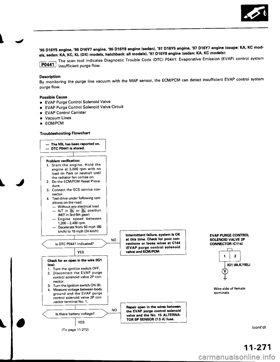
The scan tool indicates Diagnostic Trouble code (DTC) P0441: Evaporative Emission (EVAP) control system
insufficient purge flow.
Description
By monitoring the purge line vacuum with the MAP sensor, the ECM/PCM can detect insufficient EVAP control system
purge flow.
Possible Cau3e
. EVAP Purge Control Solenoid Valve
. EVAP Purge Control Solenoid Valve Circuit
. EVAP Control Canister
. Vacuum Lines
. ECM/PCM
Troubl93hooting Flowchart
Wire side of femaleterminals
EVAP PURGE CONTROI-sottNotD vALvE 2P
CoNNECTOR (Cl1al
r-+-r
I'l'l
lG-ro.*l'rr"r
O)
Y
(cont'd)
11-271
- The MIL has bsGn.eportad on.- DTC milal k rtored.
Pioblem vsrificJtion:1. Start the engine. Hold the
engine at 3,000 rPm with no
load {in Park or noutral) until
the radiator fan comes on.
2. Do the ECM/PCM Reset Proce'
dure,3. Connect the SCS service con-
nector.4. Test-drive under following con-
ditions on the road- Without any electrical load- A/T in E or E Position(M/T in 3rd-sth gear)- Engine sPeed betweon
1,200 - 2.400 rpm.- Decelerate {rom 50 mph (80
knl/h)to 15 mph (24 km/h)lntormittont lailuro, sFtorn b OK
at thi. timo. Ch€ck tor Poor con'
ncction3 or looac wir.3 at C144
{EVAP purgo control tolonoid
vrtv.l .nd ECir/FCttl.
ls DTC P0441 indicatod?
Ch.ck fo. !n op€n in the wiro l|(illinel:1. Turn the ignition switch OFF.
2. Disconnect the EVAP Purgecontrol solenoid valve 2P con_
neclor,3. Turn the ignition switch ON (ll)
4. Measur€ voltage between bodyground and the EVAP Purgecontrol solenoid valve 2P con-
nector terminal No 1.
Rop.ir opor in tho wir6 b€two€n
the EVAP purgo codtiol tolonoid
v.lvo rnd tho No 15 ALIERNA'
TOR SP SENSOR 17.5 A)lu.o.
{To page 11-272)
Page 542 of 2189
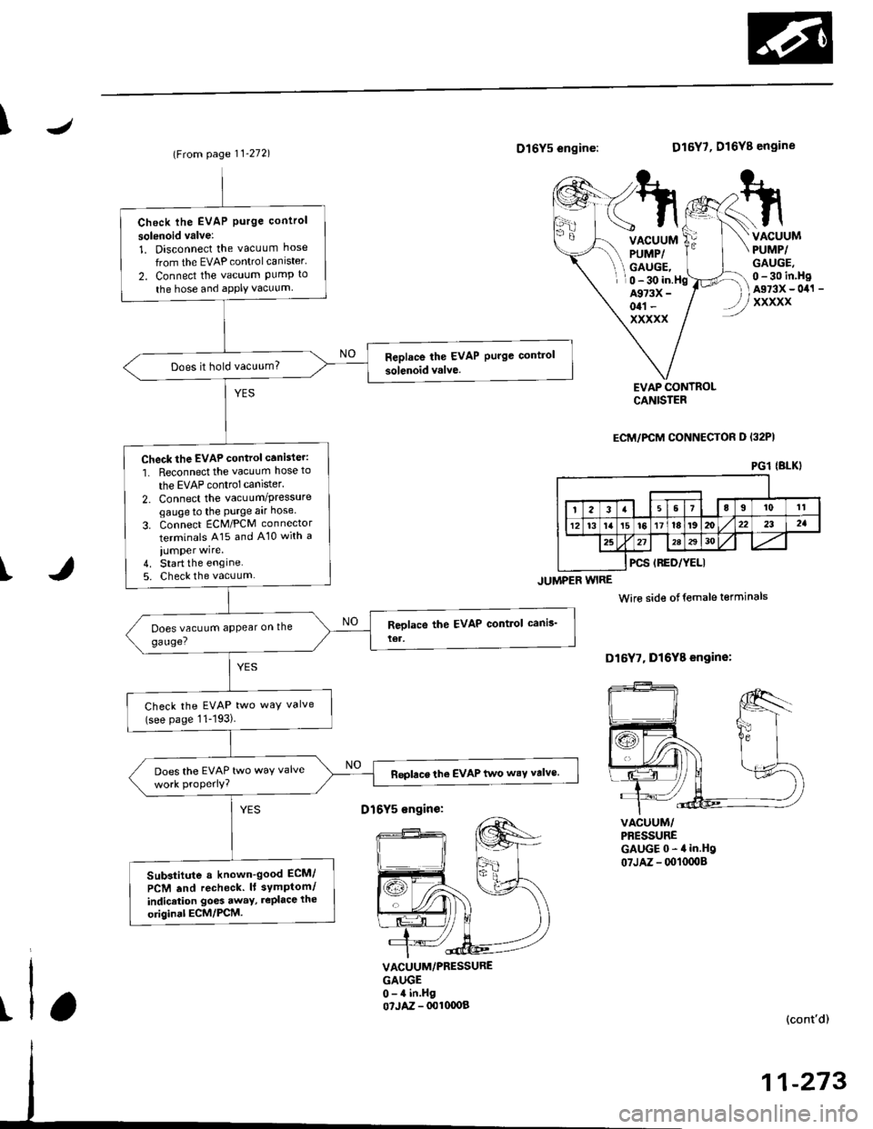
J\
(From page 11-272)D16Y5 engine:
JUMPER WIRE
D16Y7, D16Y8 engine
VACUUMPUMP/GAUGE,
VACUUMPUMP/GAUGE,0 - 30 in.HgAs73x - 0il1 -
xxxxx
0 - 30 in.HgA973X -
otl -
xxxxx
I
EVAP CONTROLCANISTER
ECM/PCM CONNECTOH D I32PI
VACUUM/PBESSUREGAUGE0-4in.Hg07JAZ - 0010008
Wire side otfemale terminals
D16Y7, Dl6Y8 engine:
t
VACUUM/PRESSUREGAUGE0-4 in.Hgo?JAZ - 001fl)OB(cont'd)
11-273
PGl IBLKI
Check lhe EVAP Purge control
solsnoid valve:
1. Disconnect the vacuum hose
from the EVAP controlcanister'
2. Connect the vacuum PumP to
the hose and aPPIY vacuum
Does it hold vacuum?
Check the EVAP control canister:
1. Reconnect the vacuum hose to
the EVAP control canlster.
2. Connect the vacuum/Pressuregaugeto the Purge aar hose
3. Connect ECM/PCM connector
terminals A15 and A10 with a
iumper wire.4. Start the engine5. Check the vacuum
Check the EVAP two way valve(see page 11-193)
Does the EVAP two waY valveReplace the EVAP two wsY valve.
Sub3titute a known-good ECM/
PCM .nd recheck. lt symPtom/
indicrtion go6s away, rePlace the
original ECM/PCM.
D16Y5 sngin€:
Page 544 of 2189
\J
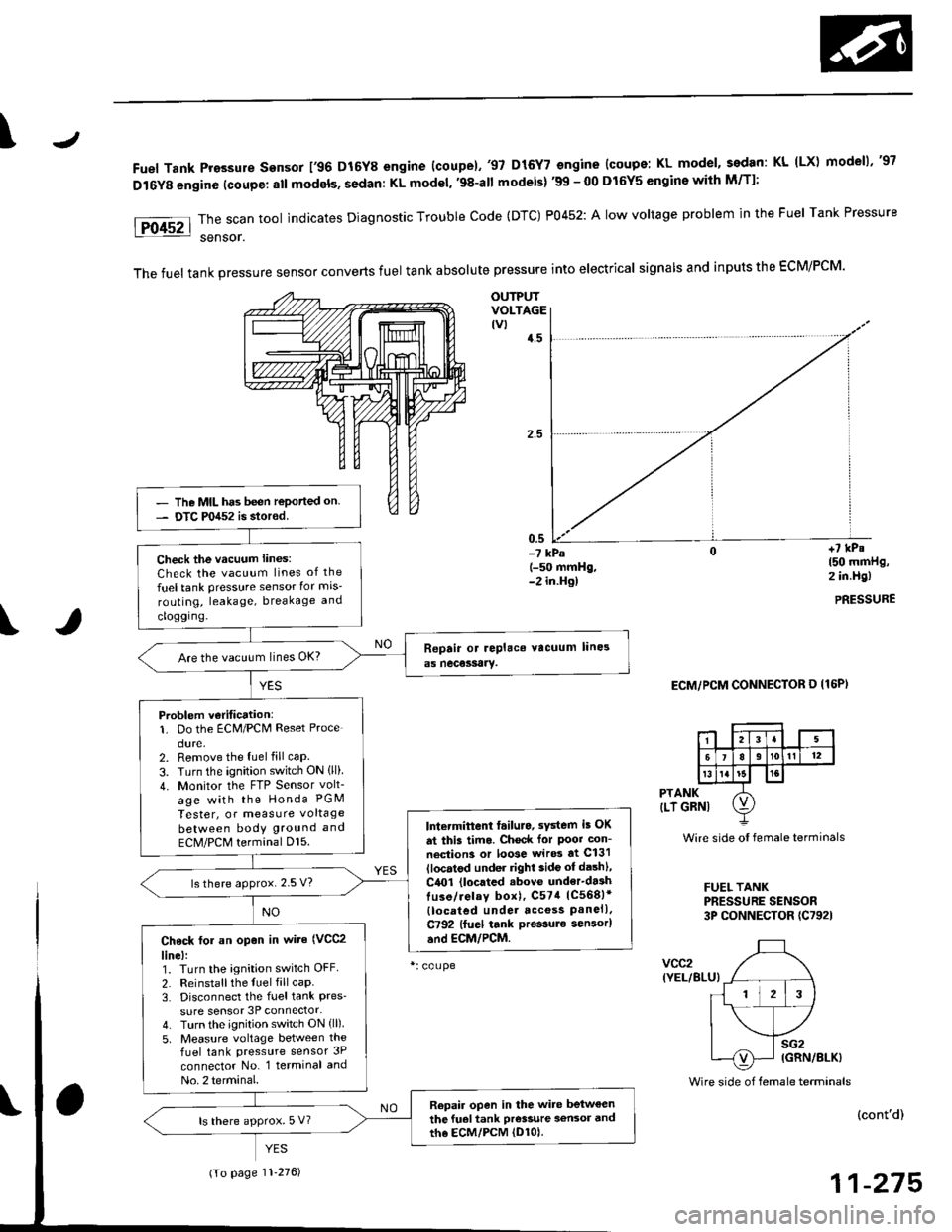
Fuel Tank Pro3sure sensor 196 D16Y8 engine (coupe).'97 D15Y7 engine {coupe: KL model, sedan: KL (LX) modeu,'97
D16Y8 engine (coupe: all models, sedan: KL model, '98-all models) '99 - 00 D16Y5 engine with M/Tl:
\
PTANK
{LT GRNI
vcc2(YEL/BLU}
Wire side oI female terminals
FUEL TANKPRESSURE SENSOR3P CONNECTOR (C7921
sG2IGRN/8LK)
Foc2l::il":"toolindicatesDiagnosticTroublecode(DTc)P0452:A|owvo|tageprob|emintheFue|TankPressure
The fuel tank pressure sensor converts fuel tank absolute pressure into electrical signals and inputs the EcM/PCM.
OUTPUTVOLTAGEtvt4.5
-? kPa(-50 mmHg,-2 in.Hg)
ECM/PCM CONNECTOR O I16P)
Wire side of female terminals
+7 kPs150 mmHg,2 in.Hg)
PRESSURE
(cont'd)
11-275
- The MIL has been reported on- DTC P0452 is stored.
Check the vacuum lines:
Check the vacuum lines of the
fuel tank pressure sensor for mis-
routing, leakage, breakage and
cloggrng.
Are the vacuum lines OK?
Problem v€ritication:1. Do the ECM/PCM Reset Proce
dure.2. Remove the luel fill caP.
3. Turn the ignition switch ON lll)4. Monitor the FTP Sensor volt_
age with the Honda PGM
Tester, or measure voltage
between bodY ground and
ECM/PCM terminal Dl5.lntermittent tailuro, sYstem i5 OK
dt this timo. Chock for Poot con-
neciion3 or loose wir* at C131
llocatod under right side ot dashl,
C4O1 (located .bove under'da3htuso/ielay box), C574 1C568)*
{located under acc€ss Panell.C792 lfuel tank pressule sen3or)
and EcM/PCM.
ls there approx. 2.5 V?
Check tol an op€n in wite (VCC2
line):1. Turn the ignition switch OFF
2. Reinstallthe fuel fill caP.3. Disconnect the fuel tank Pres'sure sensor 3P connector-4. Turn the ignition switch ON (ll)
5, Measure voltage between the
fuel tank pressure sensor 3P
connector No. l terminal and
No. 2 terminal.
Repair open in the wite betweenthe fuel tank Pr€s3ure a€n3or andth6 EcM/PcM (D1ol.ls there approx. 5 V?
(To page 11'276)