primary o2 HONDA CIVIC 1999 6.G Service Manual
[x] Cancel search | Manufacturer: HONDA, Model Year: 1999, Model line: CIVIC, Model: HONDA CIVIC 1999 6.GPages: 2189, PDF Size: 69.39 MB
Page 367 of 2189
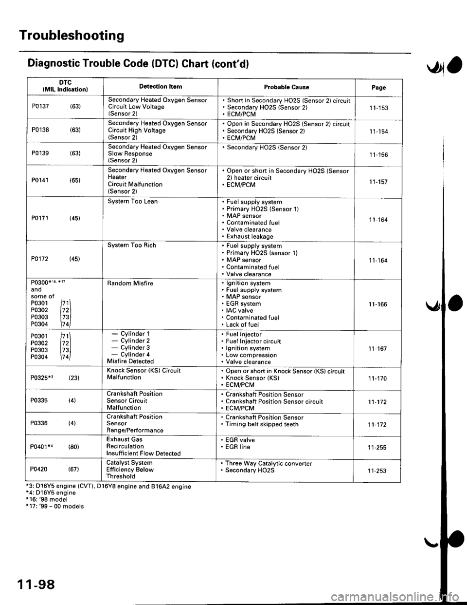
Troubleshooting
DTClMlL indicationlDatection hsmProbablo CausePage
P0137(63)Secondary Heated Oxygen SensorCircuit Low Voltage(Sensor 2)
Short in Secondary HO2S lSensor 2) circuitSecondary H02S {Sensor 2)ECM/PCI\41 1-153
P0r38 {63)Secondary Heated Oxygen SensorCircuit High Voltage(Sensor 2)
Open in Secondary HO2S (Sensor 2) circuitSecondary HO2S (Sensor 2)EC[I/PCM11-154
P0'139 (63)Secondary Heated Orygen SensorSlow Response(Sensor 2)
Secondary H02S lSensor 2)1l-156
P0141 (65)
Secondary Heated Oxygen SensorHeaterCircuit Malfunction(Sensor 2)
. Open or short in Secondary HO2S (Sensor2) heater circuit. ECM/PCM11-157
P0171 (45)
System Too LeanFuel supply systemPrimary HO2S (Sensor 1)MAP sensorContaminated fuelValve clearanceExhaust leakage
11,164
P0172 (45)
System Too RichFuel supply systemPrimary HO2S (sensor l)MAP sensorContaminated fuelValve clearance
11-164
P0300*16' }l?
andsome ofPo3o1 /r'' \P0302 l72lP0303 l73lP0304 \7 4l
Random Misfirelgnition systemFuel supply systemMAP sensorEGR systemIAC valveContaminated fuelLack of fuel
r1-r66
P0301P0302P0303P0304
/rt\172ll73l\7 4l
- Cylinder 1- Cylinder 2- Cylinder 3- Cylinder 4Misfire Detected
Fuel InjectorFuel Injector circuitlgnition systemLow compressionValve clearance
11 167
P0325*3 (23)Knock Sensor (KS) CircuitMalfunctionOpen or short in Knock Sensor (KS) circuitKnock Sensor {KS)ECM/FCtvl11-170
P0335(4)Crankshaft PositionSensor CircuitMalfunction
Crankshaft Position SensorCrankshaft Position Sensor circuitECM/PCM11-172
P0336(4)Crankshaft PositionSensorRange/Performance
. Crankshaft Position Sensor. Timing belt skipped teeth11-172
P040'�r*r (80)Exhaust GasRecirculationInsufficient Flow Detected
' EGR valve. EGR line
P0420(67)Catalyst SystemEfficiency BelowThreshold
. Th.ee Way Catalytic converter. Secondary HO2S11 253
Diagnostic Trouble Code (DTCI Chat (cont'dl
*3: D16Y5 engine (CVT), D16Y8 engine and B1642 engine*4: D'16Y5 engine*16: '98 model+17: '99 - 00 models
,Jla
1 1-98
Page 369 of 2189
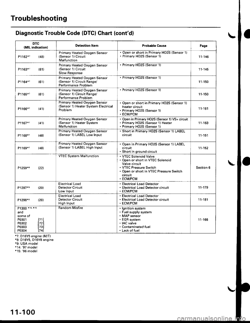
Troubleshooting
Diagnostic Trouble Code (DTGI Chart (cont'dl
*7: D16YS engine (M/T)*8: D16Y5, D'16Y8 engine*9: USA model*14r'97 model*15r '96 model
DTC(MlL indicationlDetection lt6mProbablc CausePage
P1162+1 (48)Primary Heated Oxygen Sensor(Sensor 1) CircuitMalfunction
Open or short in Primarv HO2S (Sensor 1Primary H02S (Sensor 1)1 1- 146
P]163' (61)Primary Heated Oxygen Sensor(Sensor '1) CircuitSlow Response
. Primary HO2S (Sensor 1)
11-145
Pl164*r (61)Primary Heated Oxygen Sensor(Sensor l) Cjrcuit Range/Performance Problem
. Primary HO2S (Sensor 1)
1 1- 150
P1165*? (61)Primary Heated Oxygen Sensor(Sensor 1) Circuit Range/Performance Problem
. Primary HO2S (Sensor 1)
11-150
P1166' (41i
Primary Heated Oxygen Sensor(Sensor '1) Heater System ElectricalProblem
Open or short in Primary HO2S (Sensor 1)heater circuitPrimary HO2S (Sensor 1)ECM/PCM
1 1-'161
P1167*' (41)Primary Heated Oxygen SensorlSensor 1) Heater SystemMalfunction
Open in Primary HO2S (Sensor 1) VS+ circuitPrimary HO2S (Sensor 1) HeaterPrimarv HO2S {Sensor 1)1 1- 163
P1168*' (48)Primary Heated Oxygen Sensor(Sensor 1) LABEL Low Input
. Short in Primary HO2S (Sensor 1) LABELcircuit11-151
Pl169*? (48)
Primary Heated Oxygen Sensor(Sensor 1)IABEL High Input. Open in Primary HO2S (Sensor 1)IABELcircuit. Short in ground circuit11.152
P1259*3(221
WEC System MalfunctionWEC Solenoid ValveOpen or short in WEC SolenoidValve circu itVTEC Pressure SwitchOpen or short in VTEC Pressure SwitchcircuitECM,FCM
Section 6
P1297*s (20)Electrical LoadDetector CircuitLow Input
Electrical Load DetectorElectrical Load Detector circuitECM/PCM11-179
Pr298+' l20l
Electrical LoadDetector CircuitHigh Input
Electrical Load DetectorElectrical Load Detector circuitECM/PCM1 1-181
anosome ofP0301P0302P0303P0304
l71ll72ll73ll7 4l
Bandom Misfirelgnition systemFuel supply systemMAP sensorEGR systemIAC valveContaminated fuelLack ol fuel
11-166
1 1-100
Page 373 of 2189
PGM-FI System
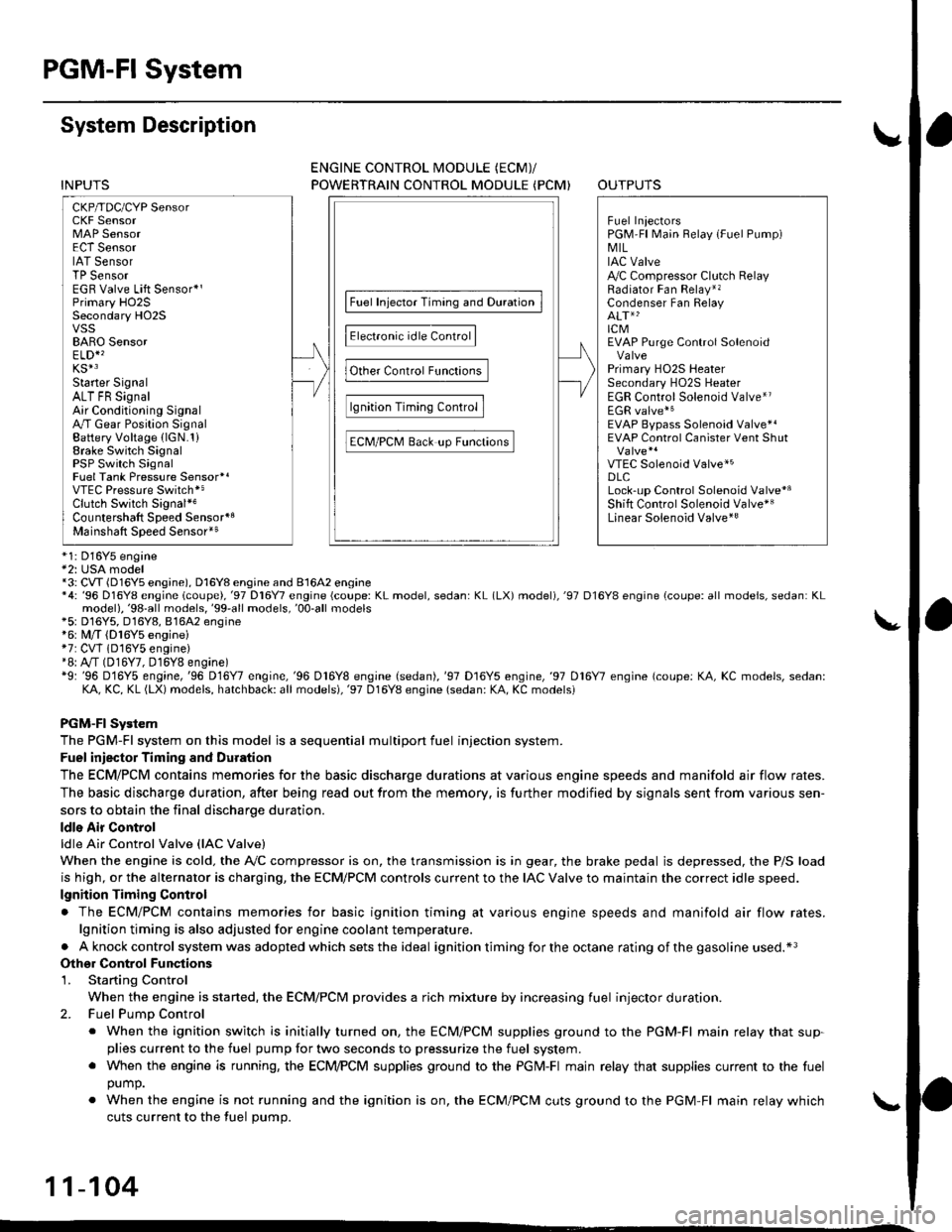
System Description
CKP/TDC/CYP Sensor
MAP Sensor
IAT SensorTP SensorEGR Valve Lift Sensor*'Primary H02SSecondary HO2SVSSBARO SensorELD*'KS€Starter SignalALT FR SignalAir Conditioning SignalA/T Gear Position SignalBattery Voltage {lGN.1}Erake Switch SignalPSP Switch SignalFuel Tank Pressure Sensor*iVTEC Pressure Switch*5Clutch Switch Signal*6Countershaft Speed SensornBMainshaft Speed Sensorrs
-\
----t /
F;ilrr j"-----fi-tri-'r.;l
Fb"t."'i" d" c;;il
F,h"'c;;tr*".io";-l
@."r.l"sc;;ll
EaM/PcM B""k-p F"""till
r\
-:/
Fuel IniectorsPGM-Fl Main Belay {Fuel Pump)MILIAC Valve!y'C Compressor Clutch RelayRadiator Fan Relay*,Condenser Fan RelayALT*'lcMEVAP Purge Control Solenoid
Primary HO2S HeaterSecondary H02S HeaterEGR Control Solenoid Valve*rEGR valve*6EVAP Bypass Solenoid Valve*'EVAP Control Canister Vent Shut
VTEC Solenoid Valve*5DLCLock-up Control Solenoid Valve*aShift Control Solenoid Valve*3Linear Solenoid Valve*3
*1: Dl6Y5 engine*2: USA model*3: CW (D16Y5 ensine), D16Y8 engine and 81642 ensine*4: '96 D16Y8 engine lcoupe),'97 Dl6Y7 engine (coupe: KL model, sedan: KL (LX) model),'97 D16Y8 engine {coupe: all models, sedan: KLmodel),'98-all models,'99'all models,'00-all models+5: D16Y5, D16Y8,816A2 engine*6: M/T (D16Y5 enginei*7: CVT 1D'l6Y5 engine)+8: A/T (D16Y7, D16Y8 engine)*9: '96 D16Y5 engine,'96 D16Y7 engine,'96 Dl6Y8 engine (sedan),'97 D16Y5 engine,'97 Dl6Y7 engine (coupe: KA, KC models, sedan:KA, KC, KL (LX) models, hatchback: all models),'97 D16Y8 engine (sedan: KA, KC modelsi
PGM-FI Sy3lem
The PGM-Fl system on this model is a sequential multipon fuel injection system.
Fuel iniector Timing and Duration
The ECM/PCM contains memories for the basic discharge durations at various engine speeds and manifold air flow rates.
The basic discharge duration, after being read out from the memory. is further modified by signals sent from various sen-
sors to obtain the final discharge duration.
ldle Air Control
ldle Air Control Valve llAC Valve)
When the engine is cold. the A,/C compressor is on, the transmission is in gear, the brake pedal is depressed, the P/S load
is high, or the alternator is charging, the ECM/PCM controls current to the IAC Valve to maintain the correct idle speed.
lgnition Timing Control
. The ECM/PCM contains memories for basic ignition timing at various engine speeds and manifold air flow rates.
lgnition timing is also adjusted for engine coolant temperature.
. Aknockcontrol system was adopted which sets the ideal ignition timing for the octane rating ofthegasoline used.*3
Othgr Control Funqtions
1. Starting Control
When the engine is started, the ECM/PCM provides a rich mixture by increasing fuel injector duration.
2. Fuel Pump Control
. When the ignition switch is initially turned on, the ECM/PCM supplies ground to the PGM-Fl main relay that sup-plies current to the fuel pump for two seconds to pressurize the fuel system.. When the engine is running, the ECI\4PCM supplies ground to the PGM-FI majn relay that supplies current to the fuel
oumo.
. When the engine is not running and the ignition is on, the ECM/PCM cuts ground to the PGM-FI main relay which
cuts current to the fuel pump.
11-104
INPUTS
ENGINE CONTROL MODULE (ECMY
POWERTRAIN CONTROL MODULE (PCM) OUTPUTS
Page 408 of 2189
Primary Heated Oxygen Sensor {Primary HO2SI (Sensor 1)
t('96 - 98 Models except Dl6Y5 engine with M/Tl
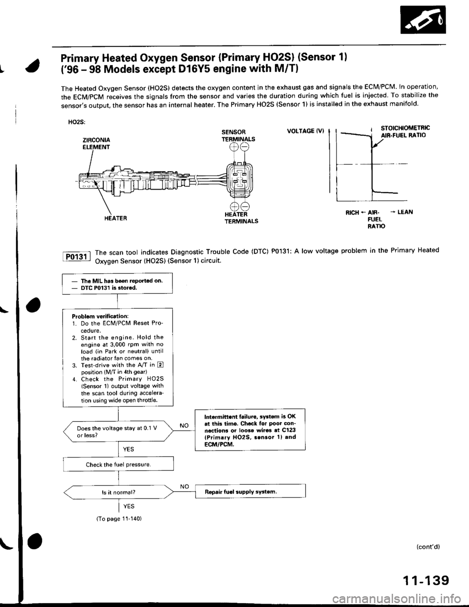
The Heated Oxygen Sensor (HO2S) detects the oxygen content in the exhaust gas and signals the ECM/PCM. In operation,
the ECM/PCM receives the sjgnals from the sensor and varies the duration during which fuel is injected To stabilize the
sensor,s output, the sensor has an internal heater. The Primary HO2S (Sensor 1) is installed in the exhaust manifold.
HO2S:
VOLTAGE {VI
The scan tool indicates Diagnostic Trouble Code (DTC) P0131; A low voltage
Oxygen Sensor (H02S) (Sensor 1) circuit.
R|cH-AIR- - LEANFUELRANO
problem in the Primary Heated
SENSOR
ztRcoNlA
The MIL has be€n teported on.DTC P0131 is siorcd.
Problom verificalion:1. Do the ECM/PCM Reset Pro'
cedure.2. Start the engine. Hold theengine at 3,000 rpm with noload (in Park or neutral) untilthe radiator fan comes on,3. Test-drive with the A/T in Eposition (M/T in 4th gear)
4. Check the Primary HO2S(Sensor 1) output voltage with
the scan tool during accelera-
tion using wide open throttle.
lntcrmift€nt failura, 3Y3tem is OKat this tims. Check for Poor con-nections or loo3e wi.o3 at C123(Primlry HO2S, 3sn3or 1) and
ECM/PCM,
(To page 1I-140)
{cont'd)
1 1-139
Page 409 of 2189
PGM-FI System
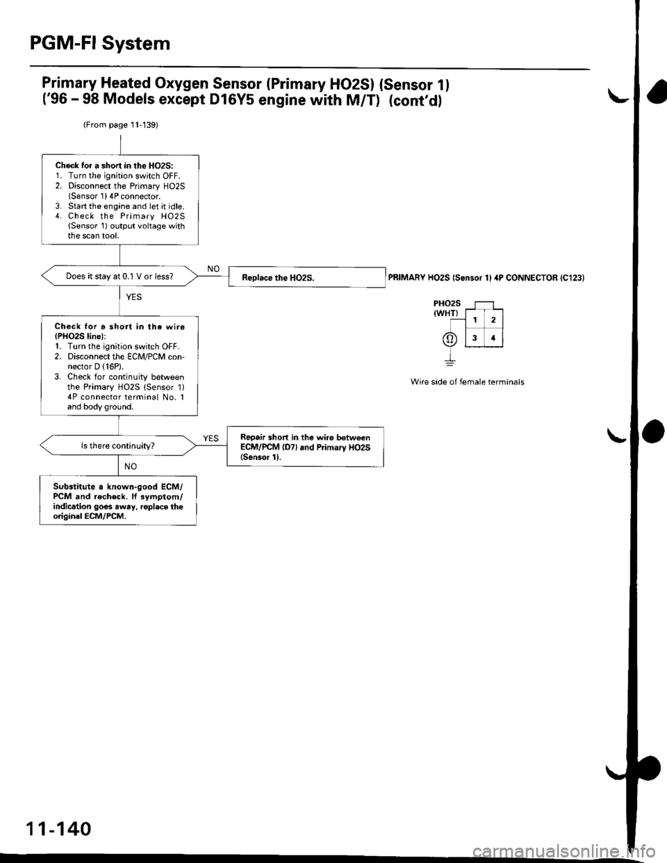
(From page 11-139)
Check for a shon in the HO2S:1. Turn the ignition switch OFF.2. Disconnect the Primary HO2S(Sensor 1) 4P connector.3. Start the engine and let it idle.4. Check the Primary HO2S(Sensor 1)output voltage withthe scan tool,
Does it stay at 0.1 V or less?
Check for a short in lhe wire(PHO2S linel:1. Turn the ignition switch OFF.2. Disconnect the ECM/PCM con-nector D ('l6P).
3. Check for continuity betweenthe Primary HO2S lsensor 1)4P connector terminal No. 1and body ground.
Repair short in lhe wire b6tw6enECM/rcM (D7) and Primary llO2S{Sensor 1}.
Substitute a known-good ECM/PCM and recheck. ll symptom/indication goes awry, replaco theoriginal ECM/PCM.
Primary Heated Oxygen Sensor (Primary HO2S) (sensor 1l
('96 - 98 Models except Dl6Y5 engine with M/T) (cont'dl
PRIMARY HO2S lsonsor 1l ,tP CONNECTOR lC123l
Wire side of female terminals
11-140
Page 410 of 2189
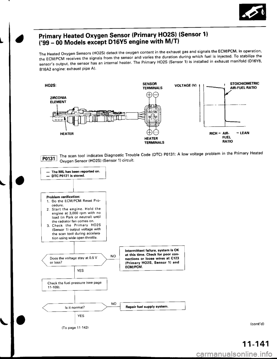
Primary Heated Oxygen Sensor (Primary- Fjq?S) (Sensor 1l
('99 - 0b Models exiept D16Y5 engine with M/T)
TheHeatedoxygensensors(Ho2S)detecttheoxygencontentintheexhaustgasandsigna|stheEcM/PcM'|noperation,
the EcM/pcM receives the signars from the sensor and varies the duration during which fuel is injected. To stabilize the
sensor,soutput,thesensornasaninternaIheater.ThePrimaryHo2S(sensorl)isinsta|ledinexhaustmanifo|d(D16Y8.
81642 engine: exhaust PiPe A)
SENSORTERMINALSVOLTAG€ (VI
HEATERTERMINALS
The scan tool indicates Diagnostic Trouble Code (DTC) P0131: A low voltage
Oxygen Sensor (HO2S) (Sensor 1) circuit
RICH+ AIR- - LEANFUELRATIO
problem in the Primary Heated
HEATER
- The MIL has been t€Ported on.- DTC P013'l is stored.
Problem veritication:1. Do the ECM/PCM Reset Pro-
2. Start the engine. Hold the
engine at 3,000 rpm wrth no
load (in Park or neutral) until
the radiator fan comes on
3. Check the PrimarY HO2S
lSensor 1) output voltage wath
the scan tool during accelera
tion using wide open throttle
lntermittont f.ilure, 3ystem i3 OK
at thi3 time. Check tor Poor con'
nections or loose wires el C123
{Primary HO2S, Sensor 1) and
ECM/PCM.
Does the voltage stay at 0 5 v
or less?
Check the fuel pressLlre (see Page11,109).
(To page 11 142)(cont'd)
11-141
Page 411 of 2189
PGM-FI System
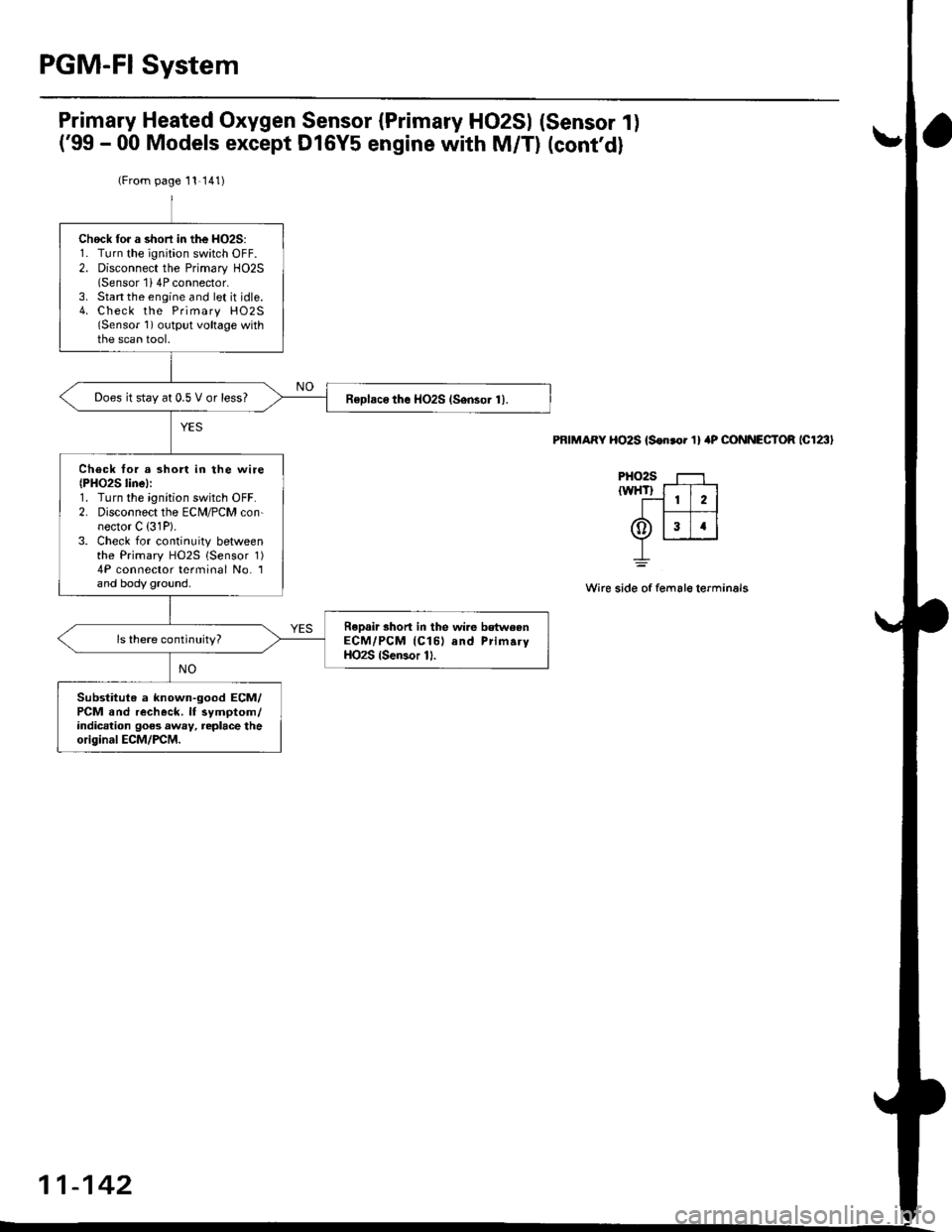
Primary Heated Oxygen Sensor (Primary HO2SI (Sensor 1)
('99 - 00 Models except Dl6Y5 engine with M/T) (cont'd)
PRIMARY HO2S {S€oror 1} 4P CONNECTOR lc123l
PHO2S f----l,wHl_l:-f;-l
0ffi
_L
Wire side of female terminals
(From page 11 141)
Chock fo. a shori in the HO2S:1. Turn the ignition switch OFF.2. Disconnect the Primary HO2S(Sensor 1i 4P connector.3. Stan the engine and let it idle.4. Check the Primary HO2S(Sensor 1) output voltage withthe scan tool.
Does it stay at 0.5 V or less?Roplaco the HO2S (Sensor 1).
Check tor a short in the wire{PHO2S linel:1. Turn the ignition switch OFF.2. Disconnect the EcltI/PcM con-nector C {31P).3. Check for continuity betweenthe Primary HO2S lsensor 1)4P connector terminal No. 1and body ground.
ReDair shorl in the wi.e betweenECM/PCM (Cl61 and PrimaryHO2S (Sercor 11.
Substitute a known-good ECM/PCM and recheck. lf symptom/indication goes away, replace theoriginal ECM/PCM.
11-142
Page 412 of 2189
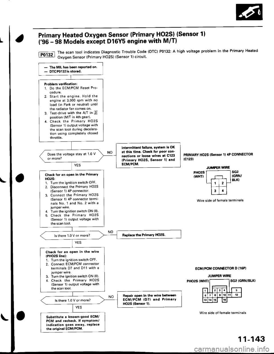
Primary Heated Oxygen Sensor (Primary HO2SI (Sensor 1)
('96 - 9b Models except Dl6Y5 engine with M/Tl
PHO29IWHT}
The scan tool indicates Diagnostic Trouble Code (DTC) P0132: A high voltage problem in the Primary Heated
Oxygen Sensor (Primary H02S) (Sensor'l) circuit.
PRIMARY HO2S (Sonso. 'll 4P CONNECToR
tc123t
sG2IGRN/BLKI
Wire side ot female terminals
ECM/PCM CONNECTOR D I16PI
JUMPER WIRE
PHO2S (WHT}SG2 IGRN/BLKI
Wire side of tem6le terminals
Probl€m verification:1. Do the ECM/PCM Reset Pro-
cedure.2. Start the engine. Hold the
engine at 3,000 rpm with no
load (in Park or neutral) until
the radiator fan comes on
3. Test-drive with the A/T in Eposition (M/T in 4th gear)
4. Check the PrimarY HO2S(Sensor 1) oLltPut voltage with
the scan tool during decelera'tion using completely closed
throttle.
Int.rmittont fiilur., system it OK
at thb timo. Chock for Poot con-
nections or loo3a wir63 at Cl23
lPrimarY HO2S, SensoJ 1l .nd
ECM/PCM.
Does the voltage stay at 1.0 V
or more?
Check for an open in the Primary
HO2S:1. Turn the ignition switch OFF.
2. Disconnect the Primary HO2S(Sensor 1) 4P connector'
3. Connect the PrimarY HO25
lSensor l) 4P connector termi-
nals No. 1 and No. 2 with a
4. Turn the ignition switch ON (ll).
5. Check the PrimarY H02S(Sensor 1i outPut voltage with
the scan tool.
lsthere 1.0 V or more?
Check for an open in the wiro
{PHO2S line):1. Turn the ignition switch OFF.
2. Connect EcM/PcM connector
terminals D7 and D11 with ajumper wrre,3. Turn the ignition switch ON lll)4. Check the PrimarY HO2S(Sensor 1) output voltage withthe scan tool,
Replir open in tho wirc b€twccnECM/PCM lo?) and Prim!.Y
HO2S lsonsor 1).ls there 1.0 V or more?
Substitute a known-good ECM/PCM and recheck. lf 3ymptom/indicetion goos awey, roplacethe oliginal ECM/PCM.
11-143
Page 413 of 2189
PGM-FI System
Primary Heated Oxygen Sensor (Primary HO2SI (Sensor 1)
('99 - 00 Models except D16Y5 engine with M/T)
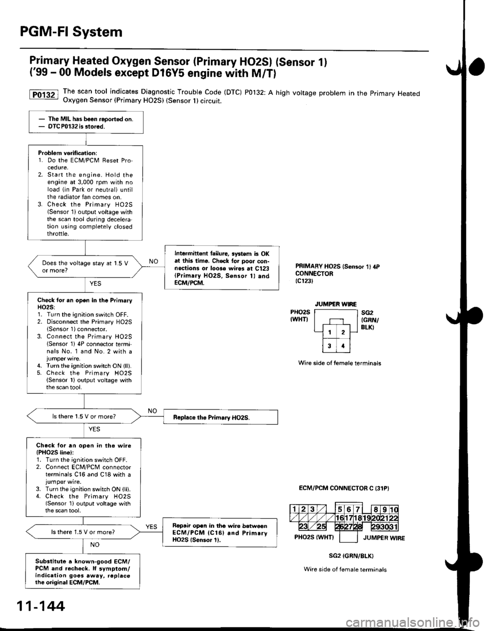
The scan tool indicates Diagnostic Trouble Code (DTC) P0132: A high voltage problem in the primary HeatedOxygen Sensor (Primary HO2S) {Sensor I ) circuit.
PRIMARY HO2S ls€n3or 1' 4PCONNECTOR(c123t
PHO2SIWHTI
Wire side of temale terminals
ECM/PCM CONNECTOR C 131PI
sG2(GRN/
BLK)
SG2 IGRN/8LK}
Ware side of female terminals
The MIL has been reported on.OTCP0132 is stored.
Problem vorificalion:1. Do the ECM/PCM Reset Procedure,Start the engine. Hold theengane at 3,000 rpm with noload (in Park or neutral) untilthe radiator fan comes on.Check the Primary HO25{Sensor lioutput voltage withthe scan tool during decelera-taon using completely closedthrottle.
Intermittent tailure, systom k OKat this time. Chock tor poor con-nections or looso wir* at Cl23(Primaly HO2S, Sonsor 1) andECM/PCM.
Check lor an open in the PrimaryH02S:1. Turn the ignition switch OFF.2. Disconnect the Primary HO2SlSensor 1)connector.3. Connect the Primary H02S(Sensor 1)4P connector terminals No. 1 and No. 2 with a
4. Turn the ignition switch ON (ll).5. Check the Primary H02S{Sensor l) output voltage withthe scan tool.
ls there 1.5 V or more?
Check lor an open in th€ wire(PHO25 lin€l:1. Turn the ignition switch OFF.2. Connect ECM/PCM connectorterminals C16 and C18 with ajumper wire.3. Turn the ignition switch ON {lli.4. Check the Primary HO2S(Sensor 1i output voltage withthe scan tool,
Roptir op.n in tho wire betweonECM/PCM lCl6l and Prim.ryHO2S lsensor 11.
ls there 1.5 V or more?
Subsiitute a known-good ECM/PCM and r.check. lf symptom/indication goos away, replecethe original ECM/PCM.
11-144
Page 414 of 2189
Primary Heated Oxygen Sensor (Primary HO2S) (Sensor 1l
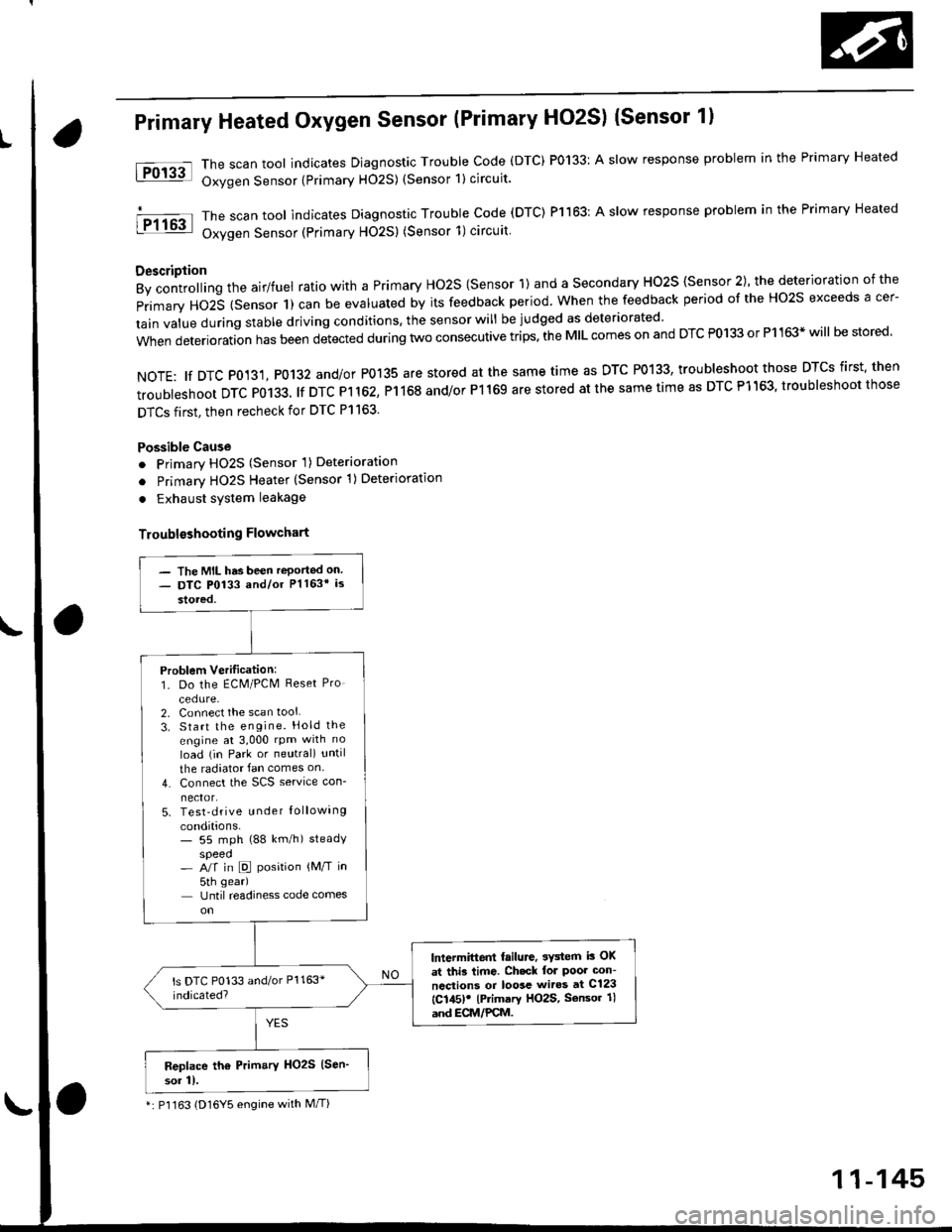
The scan tool indicates Diagnostic Trouble Code (DTC) P0133: A slow response problem in the Primary Heated
Oxygen Sensor {Primary H02S) (Sensor 1) circuit.
The scan tool indicates Diagnostic Trouble code (DTC) Pl163: A slow response problem in the Primary Heated
Oxygen Sensor (Primary HO2S) (Sensor 1)circuit
Description
By controlling the airlfuel ratio with a Primary Ho2S {Sensor 1) and a secondary HO2S {Sensor 2), the deterioration of the
primary HO2S (Sensor 1) can be evaluated by its feedback period. when the feedback period of the Ho2s exceeds a cer-
tain value during stable driving conditions, the sensor will be judged as deteriorated
when deterioration has been detected during two consecutive trips. the MIL comes on and DTC P0133 or P1163* will be stored'
NOTE: tf DTC P0131, P0132 and/or P0135 are stored at the same time as DTC P0133, troubleshoot those DTCS first' then
troubleshoot DTC P0133. lf DTC Pl 162, P1168 and/or P1169 are stored at the same time as DTC P1163, troubleshoot those
DTCS first, then recheck for DTC Pl163.
Possible Cause
o Primary HO2S (Sensor 'l) Deterioration
o Primary HO2S Heater (Sensor 1)Deterioration
. Exhaust system leakage
Troublsshooting Flowchart
tFol3al
I P1163
- The MIL has been reported on- DTC P0133 and/or Pl163* is
stored,
Problem Verilication:1. Do the ECM/PCM Reset Pro
cedure-2. Connect the scan tool
3. Start the engine. Hold the
engine at 3,000 rpm with no
load (in Park or neutral) until
the radiator fan comes on
4. Connect the SCS service con-
nector.5. Test-drive u nder Iollowing
conditions.- 55 mph (88 km/h) steadyspeed- A/f in D position {M/T in
5th gear)
Until readiness code comes
lntermittent failure, 3Y3tem i3 OK
at thi3 time. Ch.ck lol Poor con-
ncctions or loosc wiros at C123
{C145)! lPrimary HO2S, Sensor 1l
and ECM/PCM.
Replace th6 Prim.ry HO2S (Sen'
sor 11.
*: P'l163 (D16Y5 engine with M/T)
11-145