Power window HONDA CIVIC 1999 6.G Repair Manual
[x] Cancel search | Manufacturer: HONDA, Model Year: 1999, Model line: CIVIC, Model: HONDA CIVIC 1999 6.GPages: 2189, PDF Size: 69.39 MB
Page 1952 of 2189
![HONDA CIVIC 1999 6.G Repair Manual Air Delivery
- 99-00 Models
a
r--T----.I UNDER-HOOD UNDEB-DASH
| ,ry:i.l? IFUSE/RELAY I t::u:E^tt l:usE/RELAyi
- -{-;;; -
I PJ,.,8.J390 i
-
T;; ;
- - - - -
I H$3,,8
i 1;:t"* ];FPJ", i i m. HONDA CIVIC 1999 6.G Repair Manual Air Delivery
- 99-00 Models
a
r--T----.I UNDER-HOOD UNDEB-DASH
| ,ry:i.l? IFUSE/RELAY I t::u:E^tt l:usE/RELAyi
- -{-;;; -
I PJ,.,8.J390 i
-
T;; ;
- - - - -
I H$3,,8
i 1;:t"* ];FPJ", i i m.](/img/13/6068/w960_6068-1951.png)
Air Delivery
- '99-'00 Models
a
r--T----.I UNDER-HOOD UNDEB-DASH
| ,ry:i.l? IFUSE/RELAY I t::u:E^tt l:usE/RELAyi
- -{-;;; -
I PJ,'.',8.J390 i
-
T;; ;
- - - - -
I H$3,',8
i 1;:t"* ];FPJ", i i m'.u" se€power i "t8L,,
i t i a l'"0 r3l",lli"i:" aL--{..-----J L-J..----5::---:-J
"",":"rfi?ll, '[r;T:1"
-",*"1-J
*-*..l
,n", ".u I lt I
lr !I See Power I See Power Distnbution.I Distribution, U page 1o-9.
,, L::':l------- *Y=l
"*o "."",,t
[
*,:.'.Y%
Irel-
lt
:'l-4riffi
MODECONTROLMOTOR
;L:L{;I{,tt't{ {f
SensorGround grgund
venl
Air mix5Y poientia,reTgrano9 rnrrul
gIouno
RecircSwilcfi switchcommon mput
Recirc S$,itchtED LEDcontrol common
RECIRCULATIONCONTROLMOTORPHOTO 139
CONTROLPANEL
vtEw 76
So€ Roar II Windolv :
a
Htr Ttr =tr ;l *tr :tr *,tr THtr Ttr =tr ;l *tr :tr *tr Ttr
'il
Ti
Battery lgnition Mod€ Mode Mode L4ode Mode l od€(back up) input detrost h€av heat heav vent motorR€circulato Fresh
IJ
Delogger
L------- ---J
HEATERPUSHswtTcHEs
delrost
Air Airmix mixcool hot;;-; J'J - - - J-JL i- 5:- - -
SLK
812
AFN
13
BFN
See GroundDistribution,page 14-5.
c4 t, cl
WHT I ONN
ft++il
c723
F ash/RoclreSwftch
Reclrc.oat LEo
IY
tt
L__l--tGo3,
See RearWindowOetogger
AIR MIXTURECONTROLMOTOR
(
c9 Y cl1
61-2
Page 1960 of 2189
![HONDA CIVIC 1999 6.G Repair Manual Fans (contd)
- 99-00 Models
Switch"common
a,/cTHERMOSTATOff below3C (37" F).
rla
iTm,il-- l5;i;T iln"lgg1
L_t]stE"_i*-o* !-J-___i
*-"
"W"u
".*L[F*f,l" -*,"."[ftT,;.
I I .-.. Sse Power II , HONDA CIVIC 1999 6.G Repair Manual Fans (contd)
- 99-00 Models
Switch"common
a,/cTHERMOSTATOff below3C (37" F).
rla
iTm,il-- l5;i;T iln"lgg1
L_t]stE"_i*-o* !-J-___i
*-"
"W"u
".*L[F*f,l" -*,"."[ftT,;.
I I .-.. Sse Power II ,](/img/13/6068/w960_6068-1959.png)
Fans (cont'd)
- '99-'00 Models
Switch"common
a,/cTHERMOSTATOff below3'C (37" F).
rla
iTm,il-- l5;i;T iln"lgg1
L_t]stE"_i*-o* !-J-___i
*-"'
"W"u'
".*L[F*f,l"' -*,".'"[ftT,;.'
I I .-.. Sse Power II ',-.', Sse Power I S€€ Pow€r
?+ 3s;iT:3:' ?'4 3ff:?f?l:
OEE I Dbfibution,
I pacp 10.9.
HEATERCONTROLPANEL
vlEw 76
A6
BLK
;+
::--
{***,Pase*11
ItI
rfa
r,/cswitchinputL-----
HEATERPUSHswtTcHEs
A/CSwlbh
See AirDslivery,n6arWindowDelogoor
S€e AltDeliv€ry,BaarWindowD€loggpr
See GroundDistribution,pag€ 1+5.
I
J;-a;
I I 'l rHERMrsroR I Ilt | 23 9--------------2, c723q/ f, ,2tr prtoroz!3a
tttlllnr ar-x,ver- | tn*t,".u IItI
orl "tol---riliii"--
inplt (backup)
i
I
Nclsvritcn Swikh ILED LEDcontrol cofrrnon Ground _ _.i
2Yl
^..._-_I t*-*"!
t2oV c723 I
- -_-\Tgr?;u L
---rF------
requ€si
63-2
a/cONlrdlcalqr
Page 2014 of 2189
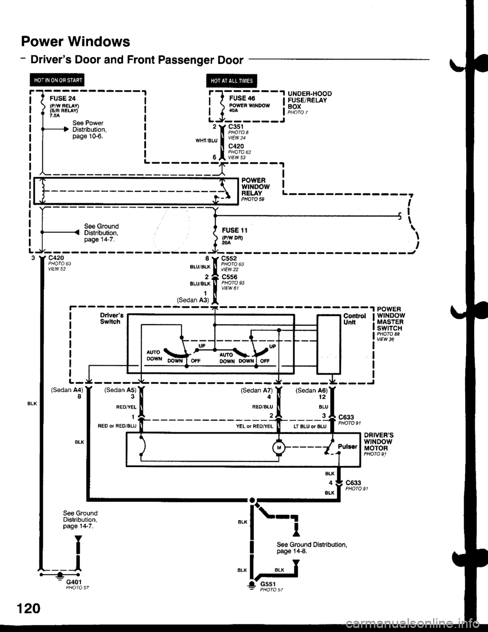
Power Windows
- Driver's Door and Front Passenger Door
FUSE 24
{s/n nElav)
Se€ PowefDistribution,page 106.
l' l-'G'-.i
- -
I i',I3.',8J39"
i ) lo1*" **oo*
i f,?T" ,
L-9------J'rF,*%,
*rtier-u |
'ry'
6I i[ff'3"
PowER !wtNDow IRELAYPHOfO 6S
see GroundDistribution,page 14-7.
I
I
I\
\
I
D ver'5SwitchContrslUnlt
POWERwtNDowMASTERswtTcrlPHATO 88vlEw 36
I
I
I
(Sedan A4)8(Sedan A5)
REO/^YEL
1
FED or aEO/BLU
(Sedan A7)4
RED/BLU
(Sedan A6)12
ALU
c633
YEL o. REo/YELLT BLU oT BLU
DRIVER'SwlNDowMOTOR
BLK
4
ALK
c633
See GroundDistribution,page 14-7.
I
I
I
See Ground Distibution,page 14€.
.---+<- G401PHOIA 57
0
c42O I Y C552
ii,?;?,* "., ".* ! f[fflo,u,
2 e C556".,,".* | f[ff11r,1 (Sedan A3) l
12
G551
Page 2016 of 2189
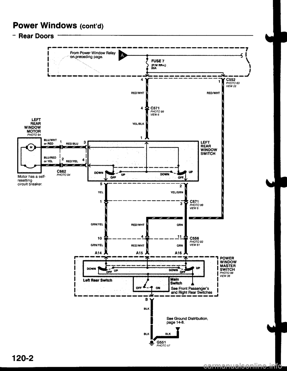
Power Windows (cont'd)
- Rear Doors
BEDAI/IITBEDAV}IT
c5?rPtlQTO 99VIEW 6
LEFTREARwtNDowswtTcH
LEFTREARwtNDowMOTOR
Motor has a selt-reseningcircuit breaker2
YEUGBN
1
Lai Rraar Sfiici
c571PHOTO
--
c556
vtEw 61
99
z
93
FEOAIVHTGRN,^/EL
10
GRN,^TEL
A14
| | Sos Front Passonoer's i
-siq-r"a{::l=-.i
qR|i
11
GFN
At6
:I
I 3s"qni'
"-l-'J
il
POWERwlNDowMASTEBSWITCH
vtEw 36
DOWiItp
Oisuibdion,
120-2
Page 2018 of 2189
Power Windows (contd)
- How the Circuit Works
CAUTION: You could iniure your arms, hands, or
fingers if you unintentionally switch the driver's
window to "automatic down" while working in
that door with the power on. Disconnect the
window switch conneclot or the battery when
working in the driver's door.
System Description
The operation of the power windows is controlled by
the main switch in the power window master switch.
When the main switch is in OFF, only the driver's door
window can be opened or closed. With the main
switch ON, all windows can be ooened or closed
either by swtches in the master panel, or swttches in
the doors. The driver's window switch also has an
automatic down mode which is tumed on by pushing
the switch down to its second oosition.
The power windows are driven by reversible motors.
Each motor is protect€d by a built-in circuit breaker.
lf the window switch is held on too long (with the
window obstructed, or after the window is fully up or
down), the circuit breaker opens the circuit. The
circuit breaker resets automaticallv as it cools.
Driver's Window
With the ignition switch in ON, voltage is provided to
the coil of the power window relay through fus€ 24.
The contacts of the power window relay close, and
voltage is applied to the driver's switch. When you
push the power window master switch to UP, voltage
is applied to the driver's window motor. (The motor's
ground path is back through the master power
window switch.) The driver's window motor then
drives the window up. When you push the switch to
DOWN, voltage is applied in the opposite direction
and the motor drives the window down.
Automatic Down (Driver's Window)
With the ignition switch in ON or START, voltage is
applied to the coil of the power window relay. The
contacts of the power window relay close and
voltage is applied lo the power window master
switch. When you push the driveas switch to the
AUTO DOWN position, voltage is applied through
the driver's switch to the driver's window motor. The
control unit receives pulses at the pulser input while
the motor is running. When the window is fully
down, the motor stops, and pulses are no longer
generated by the pulser. This is sensed by the
control unit at the pulser input, and voltage is no
longer applied to the driver's window motor.
Passenger Windows
With the ignition switch in ON, voltage is applied to
the coil of the power window relay through fuse 24.
The contacts of the power window relay then close,
applying voltage to the individual window switches
and the power window master switch. With the
master panel main switch ON, the passenger
windows can be ooerated from the individual
window switches or from tho master panel switches.
When you push the front passengsr's window
switch to UP, voltage is applied to the f ront
passenger's window motor. (The motor is grounded
through the contacts in the front passenger's
window switch and the oower window master
switch.) The window moves up as long as you hold
the switch in the UP position. lf you push the switch
to DOWN, voltage is applied in th€ opposite
direction to the front passenger's window motor, and
the window movss down as long as you hold the
switch in the DOWN Dosition. The window switches
in the other doors operate similarly.
When you push the front passenger's switch in the
master panel to UP, voltage is applied through the
front passenger's window switch contacts to the
front passengefs window motor. (The motor is
grounded through the contacts in the front
passenger's window switch and the power window
master switch.) The window moves up as long as
you hold the switch in the UP position. lf you push
the switch to DOWN, voltage is applied in the
opposite direction to lhe front passenger's window
motor, and the window moves down as long as you
hold the switch in the DOWN position. The other
passenger window switches in the master panel
operate similarly.
Refer to the Service Manual (Section 23, Electrical)
for specific tests or troubleshooting procedures.
120-4
Page 2108 of 2189
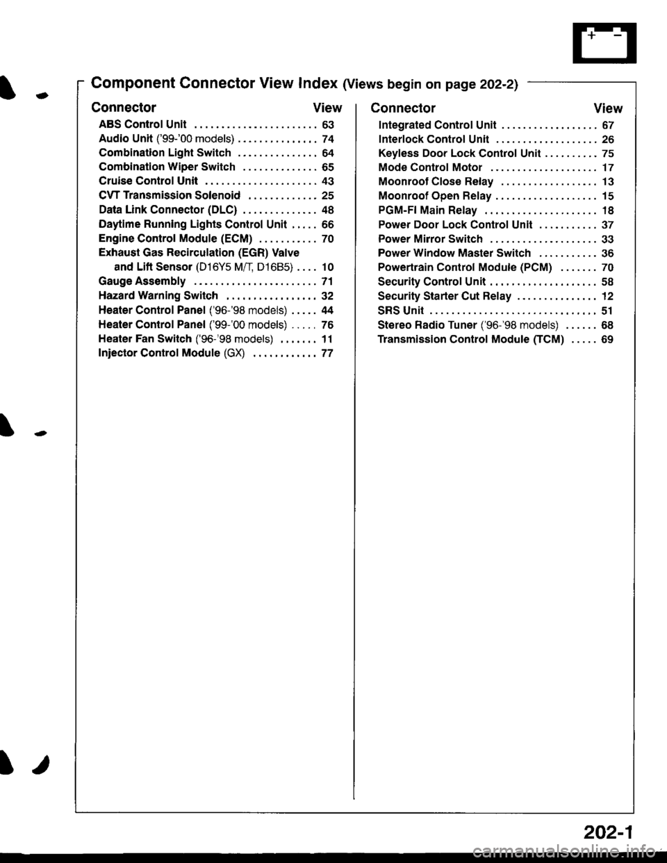
-
Component Connector View Index (Views begin on page 202-21
Connector View
ABS Control Unit........ ......63
Audio Unit ('99-'00 models) ......74
Combination Light Switch . . . . . . . . . . . . . . . 64
Combination Wiper Switch . . . . . . . . . . . . . . 65
Cruise Control Unit.... .....43
C\TTTransmission Solenoid ............. 25
Data Link Connector (DLC) ..... 48
Daytime Runnlng Lights Control Unit ..... 66
Engine control Module (ECM) ...........70
Exhaust Gas Recirculation (EGR) Valve
and Lift Sensor (D16Y5 Mfl, D1685) . . . . 10
Gauge Assembly .............71
HazardWarnlngSwitch,,. .,,,...,,,,... 32
Heater Control Panel ('96-'98 models) .....44
Heater Control Panel ('99-'00 models) ...., 76
Heater Fan Switch ('96-'98 models) ,,,.... 11
fniector Control Module (GX) ............77
I/
202-1
Connector View
Integrated Control Unit .......,. 67
f nterfock Control Unit .... ...... 26
Keyfess Door Lock Control Unit . . . . , . . . . . 75
Mode Control Motor ... ........'17
Moonroof Close Relay .. .......13
Moonroof Open Relay ... .......15
PGM-FI Main Relay .. .......... 18
Power Door Lock Conlrol Unil ..... ...... 37
Power Mirror Switch .,... ...... 33
Power Window Master Switch .,.........36
Powertrain Control Module (PCM) .......70
Security Control Unit ..., ..,,... 58
Security Starter Cut Belay ... ...,,,....,, 12
SRS Unit ............. 51
Stereo Radio Tuner ('96-'98 models) ...... 68
Transmission Control Module CICM) .....69
Page 2109 of 2189
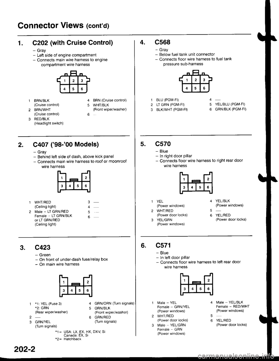
Connector Views (cont'd)
1. C202 (with Cruise Control)
- Gray- Left side ol engine compartment- Connects main wire harness to engine
compartment wre harness
gRN/BLK
(Cruise control)
BRN,ryVHT(Cruise control)
RED/BLK(Headlight switch)
BRN {Cruise conkol)
WHT/BLK(Front wipetwashel)5
4.c568
- Gray- Below Juel tank unit connector- Connects floor wire harness to tuel tank
pressure suo-narness
BLU (PGi.4-Fr)
LT GRN (PGM-FI)
BLl(WHT (PGI\4-FD
YEUBLU (PGM,FI)
GRN/BLK (PGI\,4.FD
4
5
2. C407 ('98-'00 Models)
- Gray- Behind left side ol dash, above kick panel
- Connects main wire harness to roof or moonroo{
wtre harness
WHT/RED(Ceiling light)
l\4ale - LT GRN/REDFemale - LT GRN/BLKor LT GRN/RED(Ceiling light)
5
5.c570
- Blue- In right door pillar- Connects floor wire harness to right rear door
wlre hafness
2
3
YEL(Power windows)
WHT/RED(Power door locks)
YEUGRN(Power wrndows)
YEL/BLK(Power windows)
YEURED(Power door locks)
5
6
3.c423
- Green- On Jront of under-dash tuse/relay box- On main wire harness
*1: YEL (Fuse 3)*2: GRN(Rear wiper/washe4
GRN/YEL(Turn signals)
GRN/ORN {Tu.n signals)
GRN/BLK(Front wiper/washer)
GRN/RED(Turn signals)
5
62
3
*1= USA: tX, EX, HX, DX-V SiCanada: EX, Si*2= Hatchback
202-2
6.c571
- Blue- In lett door pillar- Connects floor wire harness to lett rear door
wlre harness
MaIe _ YELFemale - GBN/YEL(Power windows)
WHT/RED(Power door locks)
Male - YEUGRNFemale - GBN(Power windows)
5
6
N4ale YEUBLKFemale - RED,ryVHT(Power windows)
YEURED(Power door locks)
Page 2113 of 2189
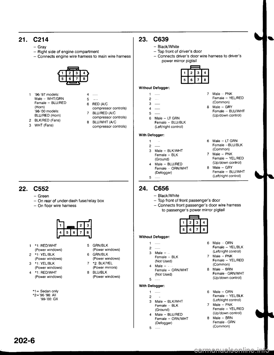
21. C214
- Gray- Right side of engine compartment- Connects engine wire harness to main wire harness
'96- 97 models:Male - WHT/GRNFemale - BLU/FED(Horn)'98-'00 models:BLU/RED (Horn)
BLKRED (Fans)
WHT (Fans)
4
5
6
7
*io t0,,"compressor controls)
BLU/RED (A,/C
compressor controls)
BLU,ryVHT (I'/C
compressor controls)
2
3
23. C639
- Black,ryVhite- Top front ot driver's door- Connects driver's door wire harness to driver's
power mirror pigtail
Without Defogger:
1
2
4
6 Male - LT GRNFema|e - BLU/BLK(Left/right control)
With Oelogger:
1
2
3 l\,lale - BLKAVHTFemale - BLK(Ground)
4 lvlale - BLU/REDFemale ORNAVHT(Delogge4
lvlale PNKFemale - YEURED(Common)
MaIe _ GRYFemale BLUA/VHT(Up/down control)
lvlale - LT GRNFemale BLU/BLK(Corrmon)
i.4ale - PNKFemale - YEURED(Up/down conkol)
Male - GRYFemale - BLU,ryVHT(Lett/right control)
22. C552
- Green- On rear of under-dash fuse/relay box- On tloor wire harness
1 *1: FEDA/VHT(Power windows)
2 *1: YEL/BLK(Power windows)
3 *1:YEL/BLK
(Power windows)
4 *1 | RED/WHT(Power windows)
*1= Sedan only*2='96''98:All'99-'00r GX
6
7
GRN/BLK(Power windows)
GRN/BLK(Power windows)*2: BLK/YEL(Power mifiors)
BLU/BLK
{Power windows)
202-6
24. C556
- Black,ryVhite- Top front of front passenger's door- Connects tront passengefs door wire harness
to passenger's power mirror pigtail
Without Defogger:
l
2
3 l\4ale -
Female BLK(Not Used)
4 l\4ale -
Female - ORN/WHT(Not Used)
With Delogger:
1
2
3 Male - BLK^VHTFemale - BLK(Ground)
4 l\.4ale - BLU/REDFemale - ORNAVHT(Defogger)
Male OBNFemale - YEUBLK(LefVright control)
l\4ale - PNKFemale - YEL/RED(Common)
Male BRNFemale - GRNA/VHT(Up/down conkol)
[.4ale - ORNFemale - YEL/BLK(Left/right control)
lrale - PNKFemale - YEURED(Up/down conkol)
l\,lale - BFNFemale'GFiN(Common)
Page 2116 of 2189
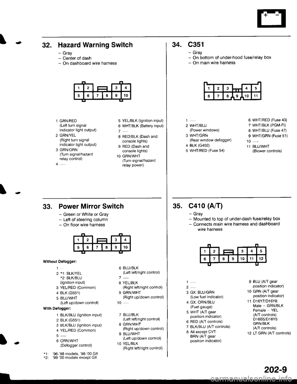
-32. Hazard Warning Switch
- Gray- Center ol dash- On dashboard wire harness
l GRN/RED(Left turn signalindicator light output)
2 GRN/YEL(Right turn signalindicator light output)
3 GRN/ORN
Ourn signal/hazardrelay control)
4
5 YEL/BLK (lgnition input)
6 WHT/BLK (Battery inpul)
7
8 RED/BLK (Dash andconsole lights)g RED (Dash andconsole lights)
1O GRNAVHT(Turn signal/hazardrelay power)
34. C351
- Gray- On bottom of under-hood fuse/relay box- On main wire harness
14
67I I9 I1011
2 WHT/BLU(Power windows)
3 WHT/GRN(Rear window defogger)
4 BLK (G402)
5 WHT/FED (Fuse 54)
6 WHT/RED (Fuse 43)
7 WHT/BLK (PGM-Fl)
8 WHT/BLU (Fuse 47)
I WHT/GRN (Fuse 51)
10 _
11 BLUAVHT(Blower controls)
33,
Without Oelogger:
1
2 *1: BLK,|YEL*2r BLKBLU(lgnition input)
3 YEURED (Common)
4 BLK (G551)
5 8LU,ryVHT(Left up/down control)
With Delogger:
1 BLIVBLU (lgnition input)
2 BLK (G551)
3 BLIVBLU (lgnition inPut)
4 YEURED (Common)
6 ORNMHT(Detogger control)
'96198 models, '98-'00 GX'99 00 models except GX
Power Mirror Switch
- Green or White or Gray- Left of steering column- On floor wire harness
6 BLU/BLK(Left left/right control)
8 YEUBLK(Right left/right control)
9 GRNAVHT(Right up/down control)
10
7 BLU/BLK(Lett left/right control)
8 GRNMHT(Right up/down control)
9 BLU/WHT(Lett up/down control)
1O YEL/BLK(Right left/right connol)
I
-
202-9
35. C41o (A/T)
- Gray- lilounted to top of underdash {use/relay box- Connects main wire harness and dashboard
wtre narness
2
3 GX: BLU/GRN
{Low fuel indicator)
4 GX: ORN/BLU(Fuelgauge)
5 WHT (A/T gearposition indicator)
6 RED (A,/T controls)
7 BLI(BLU (A,rT controls)
8 All except CVT:BRN (AiT gearposition indicator)
I BLU (Aft gearposition indicator)
10 GRN (A/I gearposition indicator)
11 D16Y7/D16Y8:Male - GRN/BLKFemale YEL(A/T conkols)D1685/D16Y5:GRN/BLK(M controls)
12 LT GRN (A/T controls)
Page 2117 of 2189
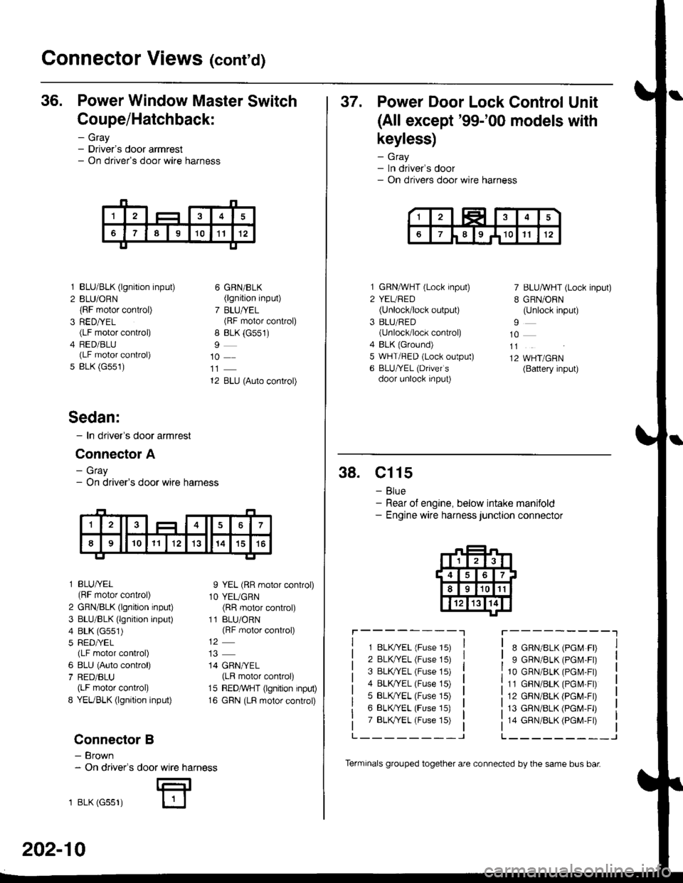
Connector Views (cont'd)
36. Power Window Master Switch
Coupe/Hatchback:
- Gray- Driver's door armrest- On driver's door wire harness
3
5
BLU/BLK (lgnition input)
BLU/ORN(RF motor control)
RED/YEL(LF motor control)
FED/BLU(LF motor control)
BLK (G551)
6 GRN/BLK(lgnition input)
7 BLU/YEL(RF motor control)
8 BLK (G551)
10
12 BLU (Auto control)
I YEL (RR motor control)
1O YEUGRN(RR motor control)
11 BLU/ORN(RF motor control)
14 GRN/YEL(LR motor control)
15 REDMHT (lgnition input)
16 GRN (LR motor control)
Sedan:
- In driver's door armrest
Connector A
- Gray- On driver's door wire harness
l BLU/YEL(RF motor control)
2 GRN/BLK (lgnition input)
3 BLU/BLK (lgnition input)
4 BLK (G551)
5 RED/YEL(LF motor control)
6 8LU (Auto control)
7 RED/BLU(LF motor control)
8 YEUBLK (lgnition input)
Connector B
- Brown- On driver's
1 BLK (Gss1)
door wire harness
E
202-10
Terminals grouped together are connected by the same bus bar
37. Power Door Lock Control Unit
(All except'99-'00 models with
keyless)
- Gray- In driver's door- On drivers door wire harness
1 GRNMHT (Lock input)
2 YEURED(Unlock/lock output)
3 BLU/RED(unlock/lock control)
4 BLK {Ground)5 WHT/RED (Lock output)
6 BLU/YEL (Drivefs
door unlock input)
7 BLU/WHT (Lock input)
B GRN/ORN(Unlock input)
10
11
12 WHT/GRN(Battery input)
38. Cl15
- Blue- Rear of engine, below intake manifold- Engine wire harness junction connector
r----------lr---------"1
1 8LK?ryEL (Fuse 15)
2 BLK/YEL (Fuse 15)
3 BLK TEL (Fuse 15)
4 BLK/YEL (Fuse 15)
5 BLK,/YEL (Fuse 15)
6 BLK/YEL (Fuse 15)
7 BLK,TYEL (Fuse 15)
8 GRN/8LK (PGM FD
9 GRN/BLK (PGM.FD
10 GRN/BLK (PGr\,4-Fr)
11 GBN/BLK (PGM-Fr)
12 GRN/BLK (PGM-FD
13 GRN/BLK (PGM-FD
14 GRN/BLK (PGM-Fr)
L_______-JL______--_J