ect HONDA CIVIC 1999 6.G Workshop Manual
[x] Cancel search | Manufacturer: HONDA, Model Year: 1999, Model line: CIVIC, Model: HONDA CIVIC 1999 6.GPages: 2189, PDF Size: 69.39 MB
Page 833 of 2189
One-way Clutch
Disassembly/lnspection/Reassembly
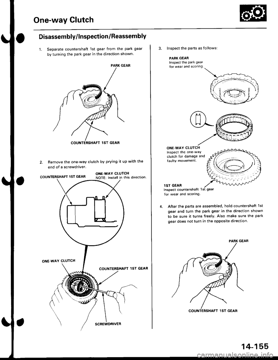
1. Separate countershaft 1st gear from the park gear
by turning the park gear in the direction shown
2. Remove the one-way clutch by prying it up with the
end of a screwdriver.
COUNTERSHAFT 1ST GEARONE-WAY CLUTCHNOTE: lnstall in this direction.
ONE'WAY CLUTCH
COUNTERSHAFT lST GEAR
COUNTERSHAFT lST GEAR
SCREWORIVER
14-155
3. Inspect the parts as followsl
PARK GEARInspecl the park gear
for wear and scorrng.
ONE-WAY CLUTCHInspect the one-way
clutch for damage and
laulty movement.
lST GEABInspect countershalt lst gear
for wear ancl scorlng.
After the parts are assembled, hold countershaft 1st
gear and turn the park gear in the direction shown
to be sure it turns freely. Also make sure the park
gear does not turn in the opposite direction.
Page 840 of 2189
Clutch
Reassembly
NOTE:
. Clean all parts thoroughly in solvent or carburetor
a
cleaner, and dry them with compressed air.
Blow out all passages.
Lubricate all parts with ATF before reassembly.
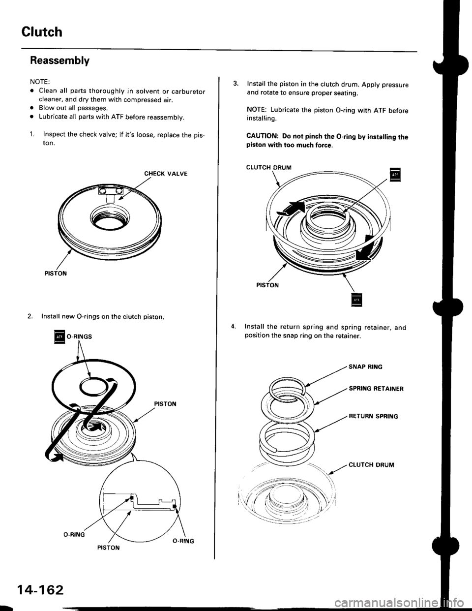
Inspect the check valve; if it's loose, replace the pis-
to n.
1.
CHECK VALVE
2. Install new O-rings on the clutch piston.
O RINGS
PISTON
-
14-162
3. Install the piston in the clutch drum, Apply pressure
and rotate to ensure proper seating,
NOTE: Lubricate the piston O-ring with ATF beforeinstalling.
CAUTION: Do not pinch the O-ring by insta ing thepiston with too much force.
CLUTCII DRUM
Install the return spring and spring retainer, andposition the snap ring on the retainer.
CLUTCI{ DRUM
Page 842 of 2189
Glutch
Reassembly (cont'd)
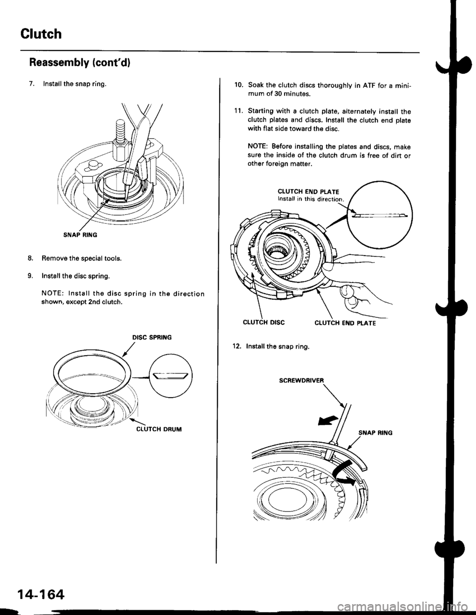
7. Installthe snap ring.
Removs the special tools.
Install the disc spring.
NOTE: Install the disc spring in the direction
shown, except 2nd clutch.
SNAP RING
8.
o
14-164
h
10.
ll.
Soak the clutch discs thoroughly in ATF for a mini-
mum of 30 minutes.
Starting with a clutch plate, alternately install the
clutch plates and discs. Install the clutch end plate
with flat side toward the disc.
NOTE: Before installing the plates and discs, make
sure the inside of the clutch drum is free of din orother foreign mafter.
CLUTCH END PLATEInstall in this direcrion.
12. Installthe snap ring.
SCREWDRIVER
SNAP RING
Page 843 of 2189
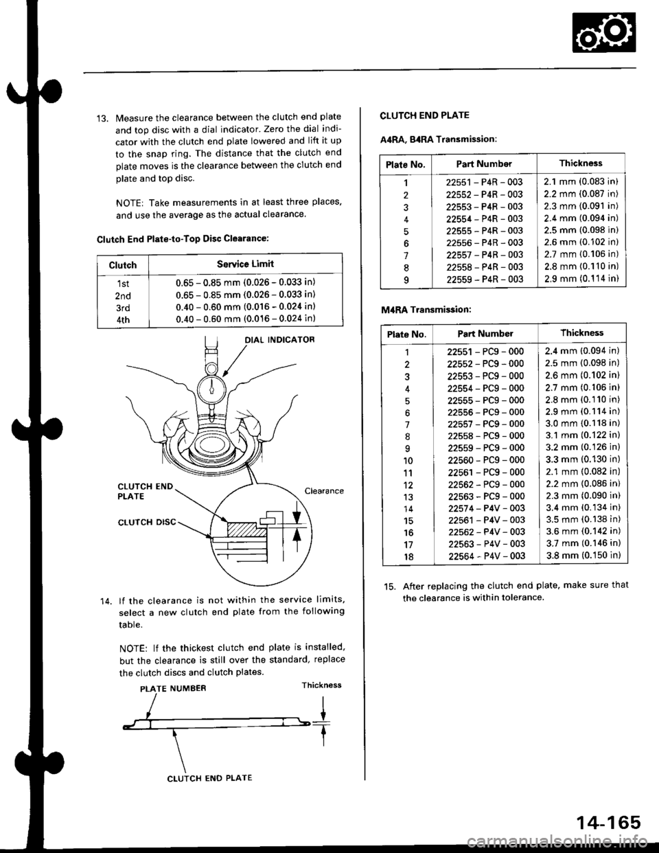
13. Measure the clearance between the clutch end plate
and top disc with a dial indicator' Zero the dial indi-
cator with the clutch end plate lowered and lift it up
to the snap ring. The distance that the clutch end
plate moves is the clearance between the clutch end
plate and top disc.
NOTE| Take measurements in at least three places,
and use the average as the actual clearance.
Clutch End Plste-to-Top Disc Clearance:
OIAL INDICATOR
CLUTCH ENDPLATEClearance
14.
CLUTCH DISC
lf the clearance is not within the service limits,
select a new clutch end plate from the following
table.
NOTE: lf the thickest clutch end plate is installed,
but the clearance is still over the standard, replace
the clutch discs and clutch plates.
PLATE NUMBERThickn6ss
ClutchSerYice Limit
1st
2nd
3rd
4th
0.65 - 0.85 mm (0.026 - 0.033 in)
0.65 - 0.85 mm (0.026 - 0.033 in)
0.40 - 0.60 mm (0.016 - 0.024 in)
0.40 - 0.60 mm (0.016 - 0.024 in)
CLUTCH ENO PLATE
14-165
Plate No.Part NumberThickness
,l
2
J
4
5
6
1
8q
22551 - P4R - 003
22552-P4R-003
22553-P4R-003
22554-P4R-003
22555-P4R-003
22556-P4R-003
22557 -P4B-OO3
22558-P4R-003
22559-P4R-003
2.1 mm (0.083 in)
2.2 mm (0.087 in)
2.3 mm (0.091 in)
2.4 mm (0.094 in)
2.5 mm (0.098 in)
2.6 mm (0.102 in)
2.7 mm {0.106 in)
2.8 mm {0.110 in)
2,9 mm (0.1 '14 in)
CLUTCH END PLATE
A4RA, g4RA Transmission:
M,IRA Transmi$ion:
15. After replacing the clutch end plate. make sure that
the clearance is within tolerance.
Plate No.Part NumberThickness
1
3
'l
.'q
10
11't2
13
14
15'16
17
18
22551 - PCg - 000
22552-PCg-000
22553-PCg-000
22554-PCg-000
22555-PCg-000
22555-PCg-000
22557-PCg-000
22558-PCg-000
22559-PCg-000
22560-PCg-000
22561 - PCg - 000
22562-PCg-000
22563-PCg-000
22574 - P4V - 003
22561 - P4V - 003
22562- P4V - 003
22563-P4V-003
22564-P4V-003
2.4 mm (0.094 in)
2.5 mm (0.098 in)
2.6 mm {0.102 in)
2.7 mm (0.106 in)
2.8 mm (0.110 in)
2.9 mm (0.114 in)
3.0 mm {0.118 in)
3.1 mm (0.122 in)
3.2 mm (0.126 in)
3.3 mm (0.130 in)
2.1 mm (0.082 in)
2.2 mm {0.086 in)
2.3 mm (0.090 in)
3.4 mm (0.134 in)
3.5 mm (0.138 in)
3.6 mm (0.142 in)
3.7 mm (0.146 in)
3.8 mm (0.150 in)
Page 844 of 2189
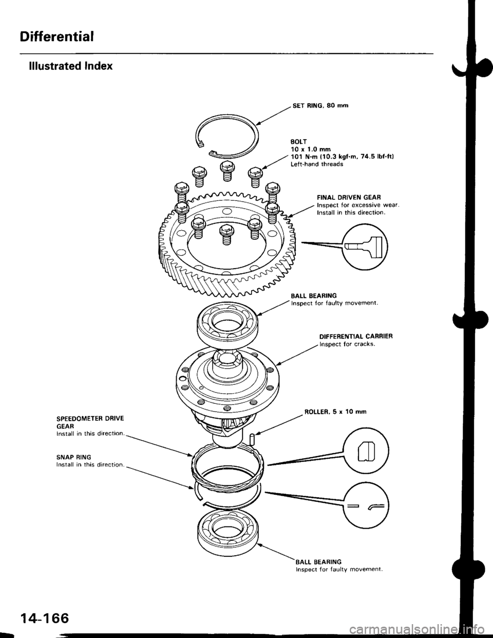
Differential
lllustrated lndex
BOLT10 r 1.0 mm'10'l N'm (10.3 k91.m,74.5 lbf.ftlLeft-hand threads
SET RING, 80 mrrt
FINAL DRIVEN GEARInspect tor excessive wear.Install in this direction.
efef
BALL BEARINGInspect for faulty movement.
DIFFERENTIAL CARRIERInsoect for cracks,
ROLLER,5x10mmSPEEDOMETER ORIVE
GEARlnstall in this direction.
SNAP RINGInstall in this direction.
EALL BEARINGInspect for faulty movement-
-
14-166
Page 845 of 2189
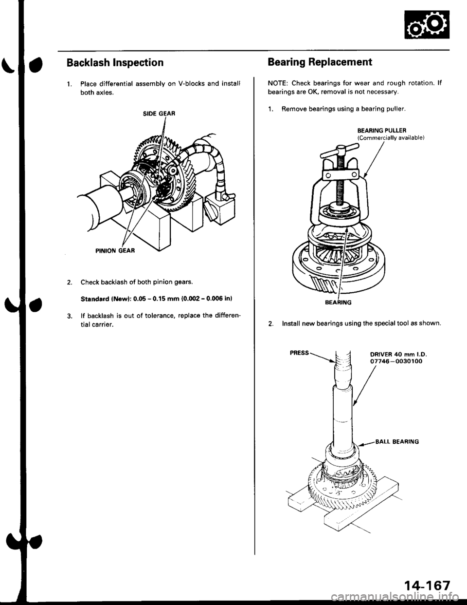
Backlash lnspection
1. Place differential assembly on V-blocks and install
both axles.
Check backlash of both pinion gears
Standard {Now): 0.05 - 0.15 mm {0.002 - 0.006 in)
lf backlash is out of tolerance, replace the differen-
tial carrier.
Bearing Replacement
NOTE: Check bearings for wear and rough rotation. lf
bearings are OK, removal is not necessary.
1, Remove bearings using a bearing puller.
BEARING PULLER(Commerci6lly available)
2. Install new bearings using the specialtool as shown.
14-167
Page 846 of 2189
Differential
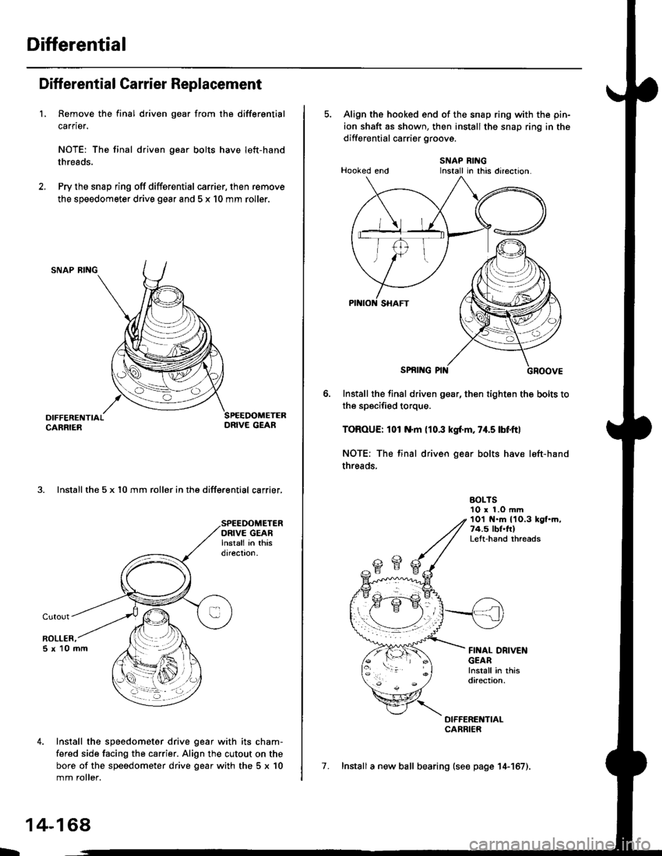
Diff erential Carrier Replacement
L Remove the final driven gear from the differential
carrier.
NOTE: The final driven gear bolts have left-hand
threads.
Pry the snap ring off differential carrier, then remove
the speedometer drive gear and 5 x 10 mm roller.
SNAP RING
3. Install the 5 x l0 mm roller in the differential carrier,
Install the speedometer drive gear with its cham-
fered side facing the carrier. Align the cutout on the
bore of the speedometer drive gear with the 5 x 10
mm roller.
L
14-168,
5. Align the hooked end of the snap ring with the pin-
ion shaft as shown, then install the snap ring in the
differential carrier groovs.
SNAP RINGHooked end Install in this direction.
SPNI G PIN
Install the final driven gear, then tighten the bolts to
the specified torque.
TOROUE: 101 N.m (10.3 kgf'm, 74.5 lbf.ftl
NOTE: The final driven gear bolts have left-hand
threads.
BOLTS10 r 1.O mm1Ol t{.m 11O.3 kgf.m,74.5 lbl.frlLeft-hand rhreads
FINAL DRIVENGEARlnstall in thisdirection.
DIFFERENTIALCARRIER
7. Install a new ball bearing (se€ page 14-157).
Install in this direclon.
Page 848 of 2189
Differential
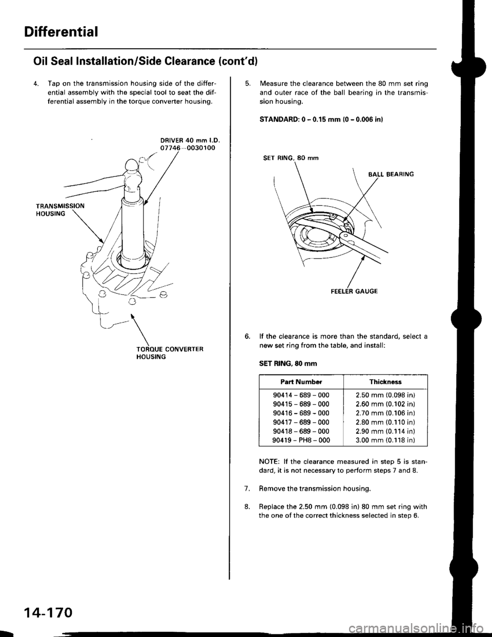
Oil Seal Installation/Side Clearance (cont'd)
4. Tap on the transmission housing side of the differ-
ential assembly with the special tool to seat the dif-
ferential assembly in the torque converter housing.
DRIVER 40 mm l.D.
L
14-170
5. N4easure the clearance between the 80 mm set ring
and outer race of the ball bearino in the transmis-
sion housing.
STANDARD: 0 - 0.15 mm (0 - 0.006 inl
SET RING, 80 mm
BALL BEARING
lf the clearance is more than the standard, select a
new set ring from the table, and install:
SET RING, 80 mm
NOTE: lf the clearance measured in step 5 is stan-
dard, it is not necessary to perform steps 7 and 8.
Remove the transmission housing.
Replace the 2.50 mm (0.098 in) 80 mm set ring with
the one of the correct thickness selected in step 6.
7.
Part NumberThickness
90414-689-000
904r5-689-000
90416-689-000
90417-689-000
90418-689-000
904r9-PH8-000
2.50 mm (0.098 in)
2.60 mm {0.102 in)
2.70 mm {0.106 in)
2.80 mm (0.110 in)
2.90 mm (0.114 in)
3.00 mm (0.118 in)
Page 852 of 2189
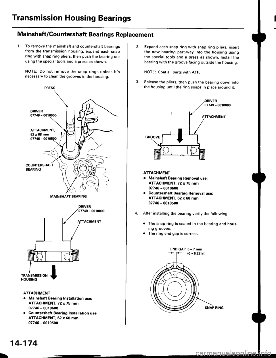
Transmission Housing Bearings
L
Mainshaft/Countershaft Bearings Replacement
To remove the mainshaft and countershaft bearings
from the transmission housing, expand each snap
ring with snap ring pliers, then push the bearing out
using the special tools and a press as shown.
NOTE: Do not remove the snap rings unless it's
necessary to clean the grooves in the housing.
DRIVER07749 - 0010000
ATTACHMENT,62x68mm
PRESS
\
07746 -
DFIVEB07749 - 0010000
TTACHMENT
ATTACHMENT
. Mainshaft Bearing Installation us€:
ATTACHMENT. 72 x 75 mm
07746 - 0010600. Countershaft Bearing Installation use:
ATTACHMENT, 62 x 68 mm
077/16 - 0010500
IRN{L{r.)n
\bZ
MAINSHAFT BEARING
L
14-174
SNAP RING
Expand each snap ring with snap ring pliers, insert
the new bearing part-way into the housing using
the special tools and a press as shown, Install thebearing with the groove facing outside the housing.
NOTE: Coat all parts with ATF.
Release the pliers, then push the bearing down intothe housing until the ring snaps in place around it.
07749 - 0010000
ATTACHMENT
. Mainshaft Bearing Removal use:
ATTACHMENT, 72 x 75 mm
077/16 - 0010600. Counte6haft Bsaring Removal use:
ATTACHMENT, 62 x 68 mm
07746 - 0010500
After installing the bearing verify the following:
. The snap ring is seated in the bearing and hous-
ing grooves.
. The ring end gap is correct.
(0 - 0.28 in)ENDGAP:0-7mm
Page 853 of 2189
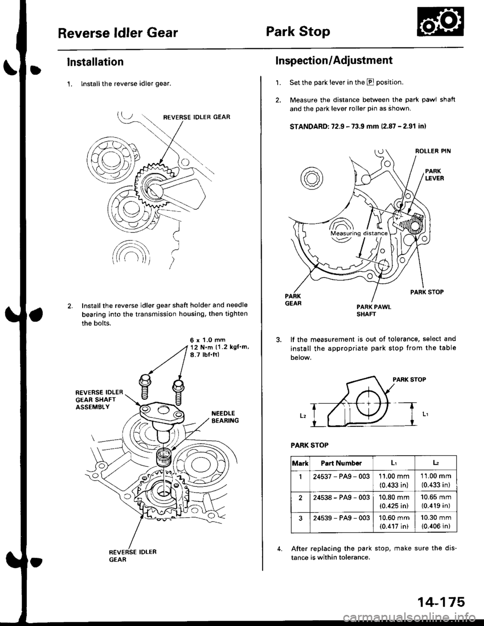
Reverse ldler GearPark Stop
lnstallation
1, lnstall the reverse idler gear.
Install the reverse idler gear shaft holder and needle
bearing into the transmission housing, then tighten
the bolts.
6 x 1.0 mm12 N.m ll .2 kgf'm,
8.7 tbf.ftl
GEAR
'1.
Inspection/Adiustment
Set the park lever in the E position.
Measure the distance between the park pawl shaft
and the park lever roller pin as ahown.
STANDARD: 72.9 - 73.9 mm 12.87 - 2.91 inl
PARK PAWLSHAFT
lf the measurement is out of tolerance, select and
install the appropriate park stop from the table
Delow.
PARK STOP
PARK STOP
After replacing the park stop, make sure the dis-
tance is within tolerance.
/A\Measuring\v
MarkPart Numb€rLr12
I24537-PAg-00311.00 mm
(0.433 in)
11.00 mm
(0.433 in)
24538-PAg-00310.80 mm(0.425 in)
10.65 mm
(0.419 in)
24539-PAg-00310.60 mm(0.417 in)
10.30 mm(0.406 in)
14-175