ect HONDA CIVIC 1999 6.G Workshop Manual
[x] Cancel search | Manufacturer: HONDA, Model Year: 1999, Model line: CIVIC, Model: HONDA CIVIC 1999 6.GPages: 2189, PDF Size: 69.39 MB
Page 884 of 2189
Description
Electronic Control System ('99 - 00 Modelsl (cont'dl
Grade Logic Control System
How it works:
The PcM compares actual driving conditions with memorized driving conditions. based on the input from the vehiclespeed sensor, the throttle position sensor, the manifold absolute pressure sensor, the engine coolant temperature sensor,the brake switch signal, and the shift lever position signal, to control shifting while the vehicle is ascending or descendinga slope.
Ascending Control
When the PCM determines that the vehicle is climbing a hill in E position, the system selects the most suitable shiftschedule (pulley ratio) according to the magnitude of a gradient. so the vehicle can run smooth and have more powerwhen needed. There are three ascending modes with different shift schedules according to the magnitude ot a gradient inthe PCM.
Descending Control
when the PCM determines that the vehicle is going down a hill in E position. the system selects the most suitable shiftschedule (pulley ratio) according to the magnitude of a gradient. This, in combinstion with engine braking, achievessmooth driving when the vehicle is descending, There are three descending modes with different shift schedules accord-ing to the magnitude of a gradient in the PCM.
L
14-206
Page 886 of 2189
Description
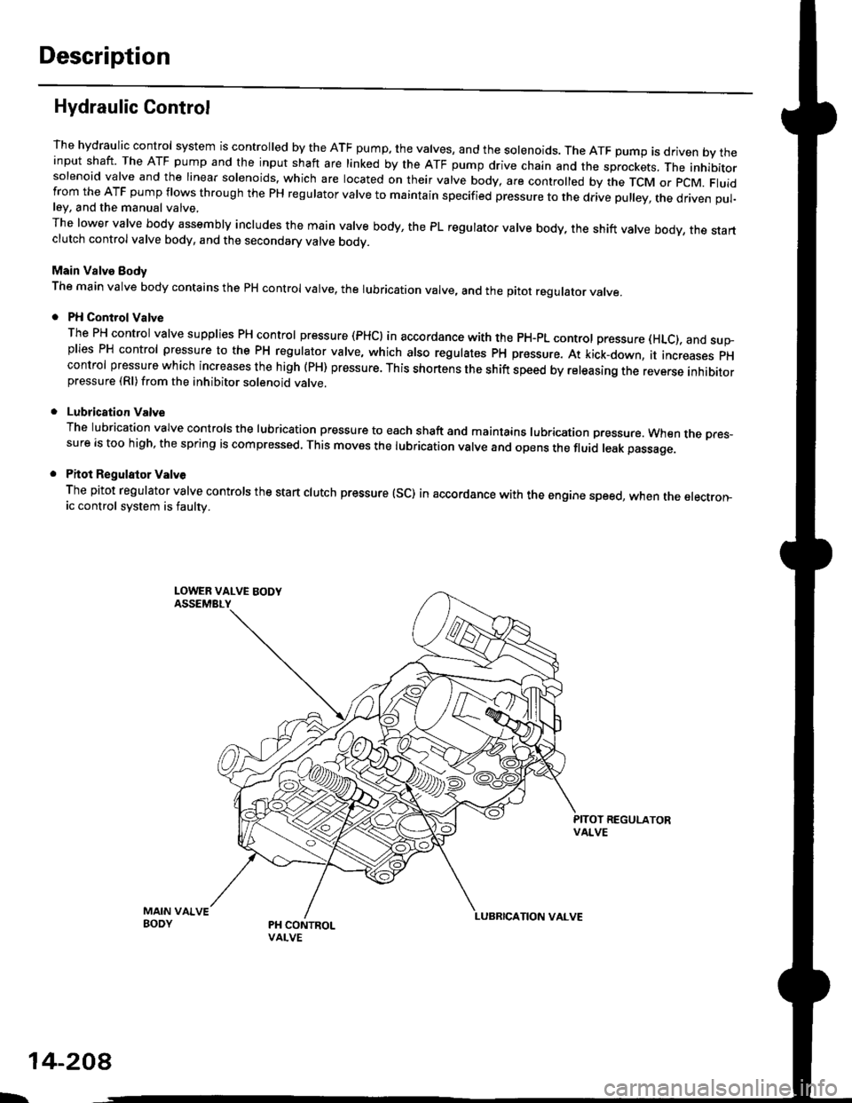
Hydraulic Control
The hydraulic control system is controlled by the ATF pump. the valves, and the solenoids. The ATF pump is driven by theinput shaft. The ATF pump and the input shaft are linked by the ATF pump drive chain and the sprockets, The inhibitorsolenoid valve and the linear solenoids. which are located on their valve body, are controlled by the TCM or pcM. Fluidfrom the ATF pump flows through the PH regulator valve to maintain specified pressure to the drive pulley, the driven pul-ley, and the manual valve,
The lower valve body assembly includes the main valve body, the PL regulator valve body, the shift valve body, the startclutch control valve body, and the secondary valve bodv.
Main Valve Eody
The main valve body contains the pH control valve, the rubrication valve, and the pitot regulator valve.
PH Control Valve
The PH control valve supplies PH control pressure (PHCI in accordance with the pH-pL control pressure (HLc), and sup-plies PH control pressure to the PH regulator valve, which also regulatss PH pressure. At kick-down, it increases pHcontrol pressure which increases the high (PH) pressure. This shortens the shift speed by releasing the reverse inhibitorpressure (Rl)from the inhibitor solenoid valve.
Lubrication Valve
The lubrication valve controls the lubrication pressure to each shaft and maintains lubrication pressure. When rne pres-sure is too high, the spring is compressed. This moves the lubrication valve and opens the fluid leak passage.
Pitot Regulalor Valv6
The pitot regulator valve controls the start clutch pressure (SC) in accordance with the engine speed, when the electron-ic control system is faulw.
MAIN VAIVEBODY
L.
14-208
Page 887 of 2189
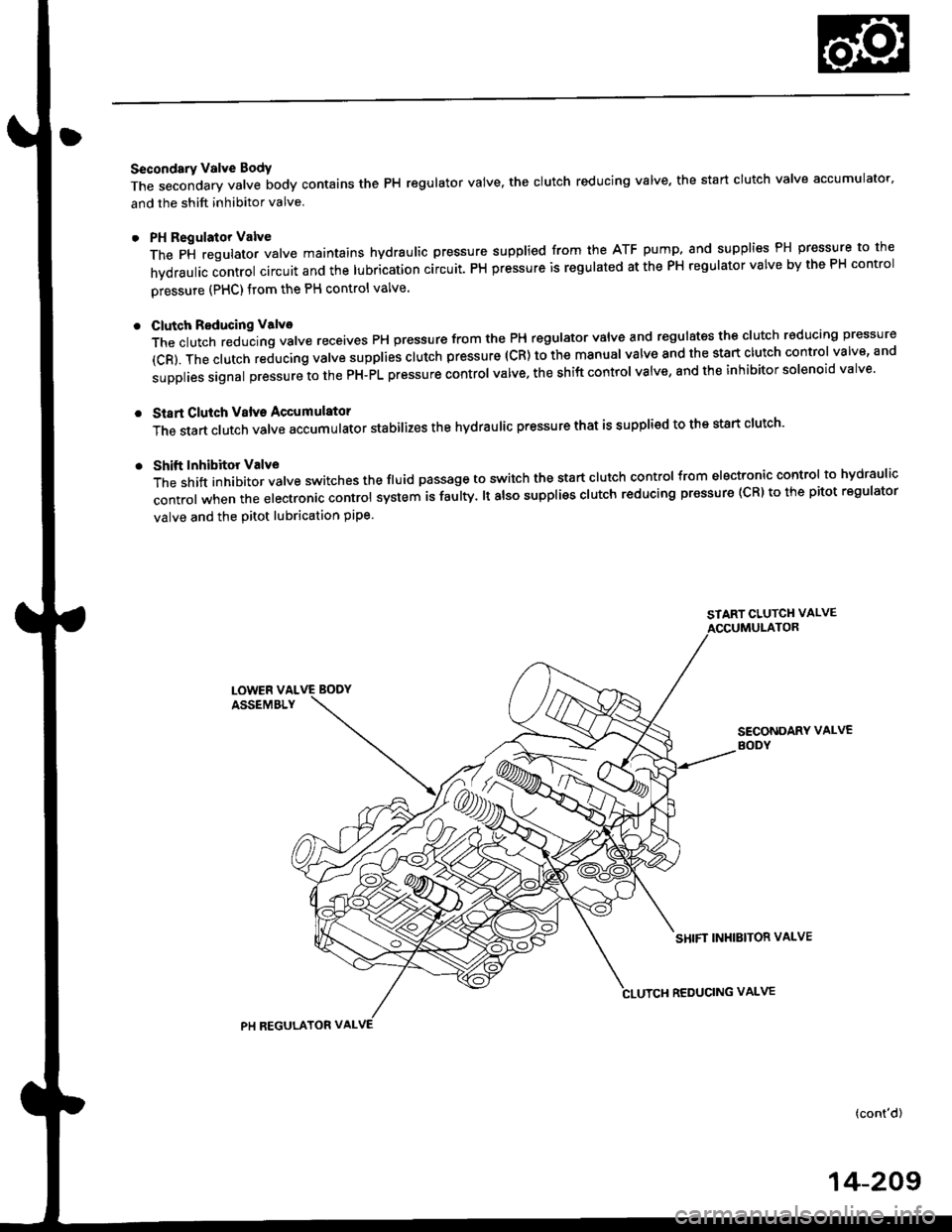
Secondary Valve Body
The secondary valve body contains the PH regulator valve. the clutch reducing valve' the start clutch valve accumulator'
and the shift inhibitor valve
PH Regulator Valve
The pi regulator valve maintains hydraulic pressure supplied from the ATF pump. and supplies PH pressure to the
hvdraulic control circuit and the lubrication circuit. PH pressure is regulated at the PH regulator valve by the PH control
pressure (PHC) from the PH control valve.
Cluteh Reducing Valvo
The clutch reducing valve receives PH pressure from the PH regulator valve and regulates the clutch reducing pressure
(cR). The clutch reducing valve supplies clutch pressure (cR) to the manual valve and the start clutch control valve' and
supplies signal pressure to the PH-PL pressure control valve. the shift control valve, and the inhibitor solenoid valve'
Start Clutch Valv€ Accumulator
The start clutch vatve accumutator stabilizes the hydraulic pressure that is supplied to the start clutch'
Shift Inhibitor Valve
The shift inhibitor valve switches the fluid passage to switch the start clutch control from electronic control to hydraulic
control when the electronic control system is faulty. lt also suppliss clutch reducing pressure (cR) to the pitot regulator
valve and the pitot lubrication pipe.
START CLUTCH VALVE
SECONDARY VALVEBODY
SHIFT INHIBITOE VALVE
(cont'd)
PH REGULATOR VAL
REDUCING VALVE
14-209
Page 891 of 2189
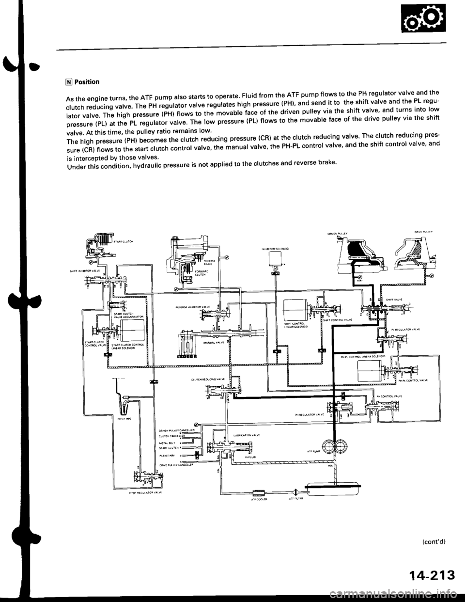
E Position
Astheengineturns.theATFpumpa|sostartstooperate.F|uidfromtheATFpumpf|owstothePHregu|atorva|veandthe
c|Utchreducingva|ve.ThePHregu|atorva|veregu|ateshighpressure(PH).andsendittotheshiftVa|veandthePLregU'
latorvalve.Thehighpressure(PH)flowstothemovablefaceofthedrivenpulleyviatheshiftvalve'andturnsintolow
pressure(PL)atthePLregu|atorva|ve.Thelowpressure(PL}f|owstothemovab|e'aceofthedrivepu||eYviatheshift
valve. At this time, the pulley ratio remarns low'
Thehighpressure(px)uecomesttrectutchreducingpressure(CR)atthec|utchreducingva|Ve.Thec|utchreducingpres.
sure (CR) flows to the start clutch cont'oi uatt". tn"lt"n'al valve' the PH-PL control valve' and the shift control valve' and
is intercepted bY those valves
Under this condition, hydraulac pressure is not applied to the clutches and reverse brake'
(cont'd)
14-213
Page 893 of 2189
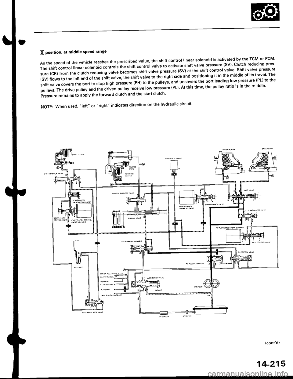
E position, at middle sPeed range
Asthespeedofthevehic|ereachestheprescribedVa|ue,theshiftcontro||inearsolenoidisactivatedbytheTcMorPcM'
Theshiftcontro||inearso|enorocontroIsttresniftcontroIVa|vetoactivateshiftVa|vepressure(SV)'c|utchreducingpres-
sure (CR) trom the clutch reduclng valve becomes shift valve pressure (SV) at the shift control valve Shift valve pressure
(SV)flowstothe|eft"noottr'"st'ittu"tue.theshiftVa|Vetotherightsideandpositioningitinthemidd|eofitstrave|.The
shift valve covers th" pon ao ",oo nLior".irr" tiHl a ,tr" pulleys, and uncovers the port leading low pressure (PL) to the
pu eys. The drive pu ey and tne oriJen priLy |."""iu" to* pressure (PL). At this time, the pulley ratio is in the middle'
Pressure remains to apply the forward clutch and the start clutch'
NOTE: When used, "|eft" or "right" indicates direction on the hydraulic circuit'
(cont'd)
14-215
Page 894 of 2189
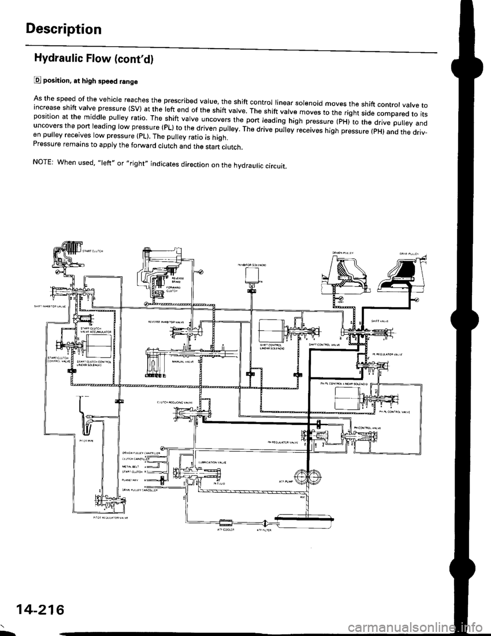
Description
Hydraulic Flow (cont'd)
@ position, at high spe6d range
As the speed of the vehicle reaches the prescribed value, the shift control linear sol€noid moves the shift contror vatve toincrease shift valve pressure (SV) at the left end of the shift valve. ttre srrit vatve moves to the right side compared to itsposition at the middle pulley ratio. The shift valve uncovers the port leading high pressure (pxito ttre d.ve puley anduncovers the port leading low pressure (PL) to the driven pulley. The drive pu|ey receives high pressure (pH) and the driv-en pulley receives low pressure (pL). The pulley ratio is high.Pressure remains to apply the forward clutch and the start clutch,
NOTE: When used, "left,, or,,right" indicates direction on the hydraulic circuit.
L
14-216
Page 895 of 2189
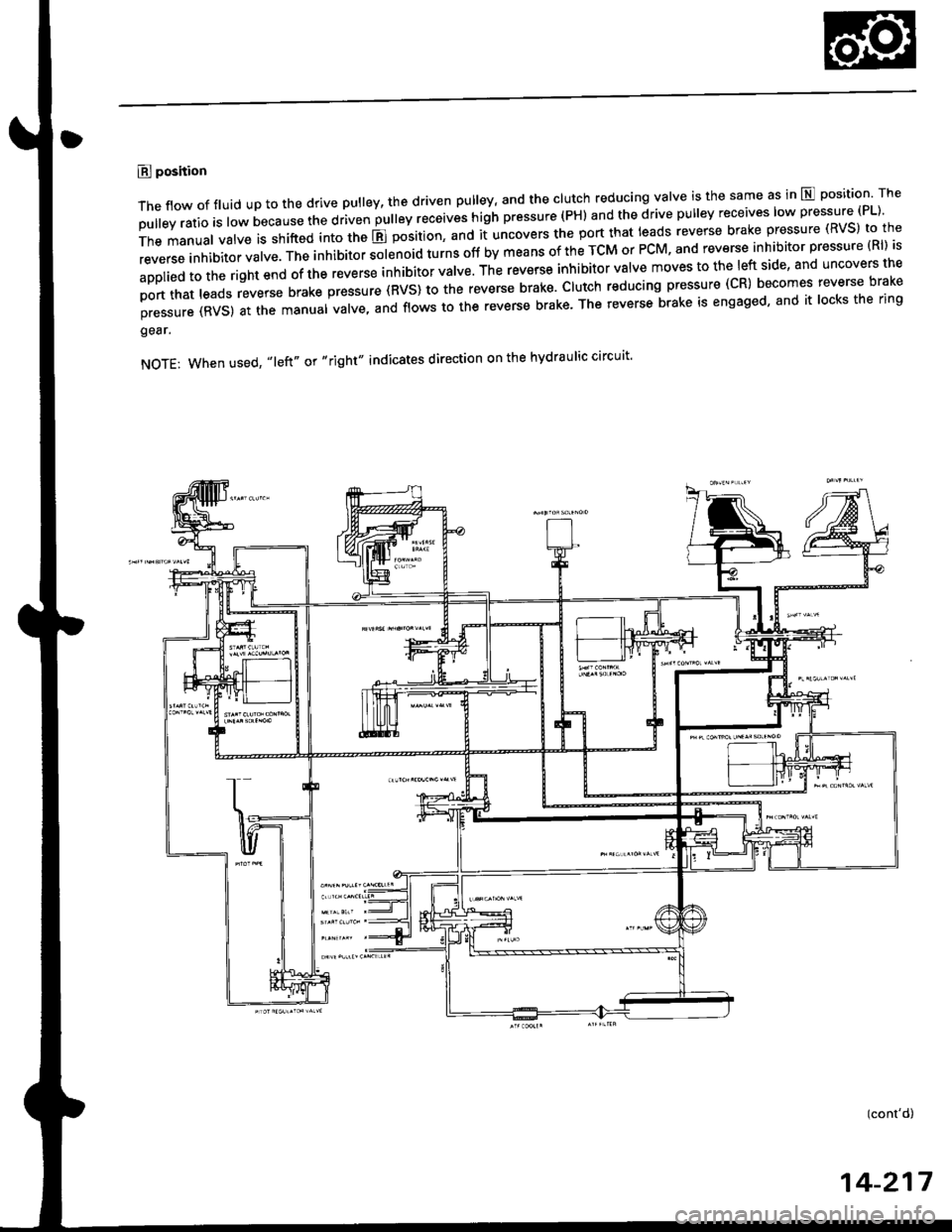
E position
The flow of fluid up to the drive pulley, the driven pulley' and the clutch reducing valve is the same as in E position The
pulley ratio is low b"car"" tt " o riu",i'prti"vi"""v"" t'igtr pressure.(pH) and the drive pulley receives low pressure {PL).
The manual valve is shifted into the B position, and it uncovers the port that leads reverse brake pressure (RVS) to the
reverse inhibitor valve. The inhibitoi Jenoid turns off by means of the TcM or PcM, and reverse inhibitor pressure (Rl) is
appliedtotherightendofthe,"u",""int,iui.o,u,|ve.Thereverseinhibitorva|vemovestothe|eftside,anduncoversthe
port that leads reverse brake pr"a"ur" tivst,o,he reverse brake. clutch reducing pressure (cR) becomes reverse brake
pressure (RVS) at the manuat *r"-, "nJ tro*" to the reverse brake. The reverse brake is engaged, and it locks the ring
gear.
NOTE: When used, "|eft" or "right" indicates direction on the hydraulic circuit'
(cont'd)
14-217
Page 896 of 2189
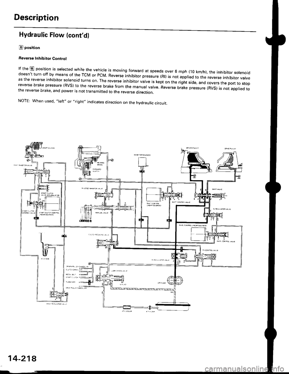
Description
Hydraulic Flow (cont'dl
E position
Reverse Inhibitor Conirol
lf the E position is selected while the veiicle is moving forward at speeds over 6 mph (10 km/h), the inhibitor solenoiddoesn't turn off by means of the TcM or PCM Reverse inhibitor pressure (Rl) is not applied to the reverse inhibitor valveas the reverse inhibitor solenoid turns on. The reverse inhibitor valve is kept on the right side, and covers the pon ro sropreverse brake pressure {RVS} to the reverse brake from the manual valve. Reverse brike pressure (RVs) i; not appried tothe reverse brake, and power is not transmitted to the reverse direction.
NOTE: When used, "left,' or,,right,, indicates direction on the hydraulic circuit.
14-218
Page 898 of 2189
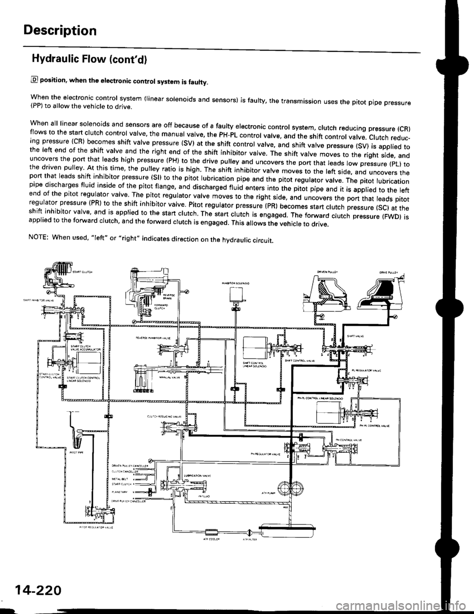
Description
Hydraulic Flow (cont'd)
lll position, when th€ electronic control system is fauhy.
when the electronic control svstem (linear solenoids and sensors) is faulty, the transmission uses the pitot pipe pressure(PP) to 311o- rh" u"hicle to drive.
when all linear solenoids and sensors are off because of a faulty electronrc control system, clutch reducing pressure (cR)flows to the start clutch control valve, the manual valve, the PH-PL control valve, and the shift control valve. clutch reduc-ing pressure (cR) becomes shift varve pressure (sV) at the shift contror varve, and shift varve pressure {sv) is appried tothe left end of the shift valve and the right end of the shift inhibitor valve. The shift valve moves to the right side. anduncovers the pon that leads high pressure (PH) to the drive pulley and uncovers the po.t tlr"t r""1" ro,,"-pressure (pL) tothe driven pulley At this time, the pulley ratio is high, The shift inhibitor valve moves to the left side, and uncovers theport that leads shift inhibitor pressure (Sll to the pitot lubrication pipe and the pitot regulator valve. tne prtot lubricationpipe discharges fluid inside of the pitot flange, and discharged fluid enters into the pitot pipe and it is applied to the leftend of the pitot regulator valve. The pitot regulator valve moves lo the right side, and uncovers the port that leads pitotregulator pressure (PR) to the shift inhibitor valve. Pitot regulator pressure {pR) becomes start clutch pressure {sc1 at theshift inhibitor valve, and is applied to the stan clutch. The stan clutch rs engaged. The forward clutch pressure (FWD) isapplied to the forward crutch, and the forward crutch is engaged. This alows the vehicre to drive.
NOTE: When used. "|eft" or ,,right', indicates direction on the hydraulic circuit.
14-220
I.
Page 899 of 2189
![HONDA CIVIC 1999 6.G Workshop Manual E] position, when the elestronic Gontrol system is faulty
The flow of tluid up to the drive pulley, the driven pulley and the start clutch is the same as in El position
The manual valve is shifted i HONDA CIVIC 1999 6.G Workshop Manual E] position, when the elestronic Gontrol system is faulty
The flow of tluid up to the drive pulley, the driven pulley and the start clutch is the same as in El position
The manual valve is shifted i](/img/13/6068/w960_6068-898.png)
E] position, when the elestronic Gontrol system is faulty'
The flow of tluid up to the drive pulley, the driven pulley' and the start clutch is the same as in El position
The manual valve is shifted into the lE position' and it uncovers the port that leads reverse brake pressure {RVS} to the
reverse inhibitor valve. Reverse ,"nlu-i,"ip*r""i" (Rl) is applied to.the right end of the reverse inhibitor valve because of
afaultyinhibitorsolenoid.The'"t'",""inftiUito'valvemovestotheleftside'anduncoverstheportthatleadsreverse
brake pressure {RVS) to the ,"u"r." ir"t"- cru,ch reducing pressure (cR) becomes reverse brake pressure (RVS) at the
manual valve, and,lows to the ,e
"rs" lr"re. ttre reverse brake is engaged and locks the ring gear' This allows the vehi-
cle to drive in reverse.
NOTE: When used, "left" or "right" indicates direction on the hydraulic circuit'
14-221