harness HONDA CIVIC 1999 6.G Repair Manual
[x] Cancel search | Manufacturer: HONDA, Model Year: 1999, Model line: CIVIC, Model: HONDA CIVIC 1999 6.GPages: 2189, PDF Size: 69.39 MB
Page 1302 of 2189
![HONDA CIVIC 1999 6.G Repair Manual Dashboard
Removal (contd)
7. lf necessary, remove the dashboard frame from the dashboard.
>: Screw localionsa>,21 B>,4a: Nut locations, 3
>: Clip locations
l^1./\
I Shl: OlbtvY/l\-]1
ra 6 x 1.0 m HONDA CIVIC 1999 6.G Repair Manual Dashboard
Removal (contd)
7. lf necessary, remove the dashboard frame from the dashboard.
>: Screw localionsa>,21 B>,4a: Nut locations, 3
>: Clip locations
l^1./\
I Shl: OlbtvY/l\-]1
ra 6 x 1.0 m](/img/13/6068/w960_6068-1301.png)
Dashboard
Removal (cont'd)
7. lf necessary, remove the dashboard frame from the dashboard.
>: Screw localionsa>,21 B>,4a: Nut locations, 3
>: Clip locations
l^1./'\
I Shl:' Olb'tvY/l\-]1
ra 6 x '1.0 mm
Yi.!i[11"-"'".
DASHBOARD BRACKETSIDE COVER
Installation is the reverse of the removal orocedure.
NOTE:
. Before tightening the bolts, make sure the dashboard wire harnesses are not pinched.a Make sure the connectors, antenna lead and air mix control cable are connected properly.
FRONT PASSENGER'S
OASHBOARD
20-72
Page 1303 of 2189
Seats and Seat Belts
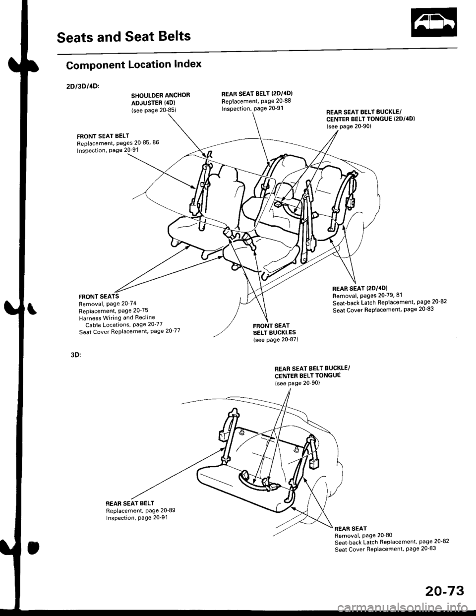
Component Location Index
2Dl3Dl1Dl
SHOULDER ANCHOR
ADJUSTER (4D)
(see Page 20-85i
FRONT SEAT BELT
Replacement, Pages 20 85,86
Inspection, Page 20-91
FRONT SEARemoval, Page 20'74
Replacement, Page 20 75
Harness Wiring and Recline
Cable Locations, Page 20-77
Seat Cover RePlacemenl, Page 2O'77
3D:
BEAR SEAT BELTReplacement, Page 20'89Inspection, page 20-91
REAB SEAT BELT (2DI4DI
Replacement, page 20-88
lnspection, page 20-91REAR SEAT EELT BUCKLE/CENTER BELT TONGUE (2DI4DI
(see p6ge 20'90)
REAR SEAT t2Dl4DlRemoval, pages 20-79, 8'l
Seat-back Latch Replacement, page 20-82
Seat Cover RePlacement, Page 20-83
FRONT SEATBELT BUCKLES{see page 20-87)
REAR SEAT BELT BUCKLE/
CENTER BELT TONGUE(see Page 20'90)
REAR SEATRemoval, page 20 80
Seat back Latch Replacement, page 20-8?
Seat Cover RePlacement, Page 20_83
20-73
Page 1305 of 2189
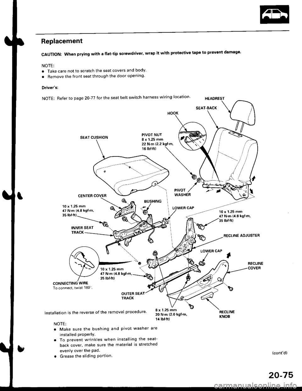
Replacement
CAUTION: When prying with a flat-tip screwdrivet, wrap it with protective tape to prevent damage'
NOTE:
. Take care not to scratch the seat covers and body
. Remove the front seat through the door openlng'
Driver's:
NOTE: Refer to page 2O-77 for the seat belt switch harness wiring location'
SEAT CUSHION
CENTER COVER
INNER SEATTBACK
PIVOT NUT8 x 1.25 mm22 N.m l.2.216 tbf.ft)
v
l
35 tbt.ft)
10 x 1.25 mm47 N.m {4.8 kgf m,10 x 1.25 mm47 N.m {i1.8 kgl m,35 tbr.ft)
RECLINE ADJUSTER
LOW
d
ER CAP
l
RECLINE
CONNECTING WIRETo connect, twist 180'
OUTER SEATTRACK
Installation is the reverse of the removal procedure'
NOTE:
. Make sure the bushing and pivot washer
installed ProPerly.. To prevent wrinkles when installing the seat-
back cover, make sure the material is stretched
evenly over the Pad.
. Grease the sliding Portion
8 x 1.25 mm20 N.m 12.0 kgf.m,14 tbt.ft)
are
RECLINEKNOB
(cont'd)
20-75
10 x 1.25 mm47 N.m {4.8 kgf'm,35 tbtftl
Page 1307 of 2189
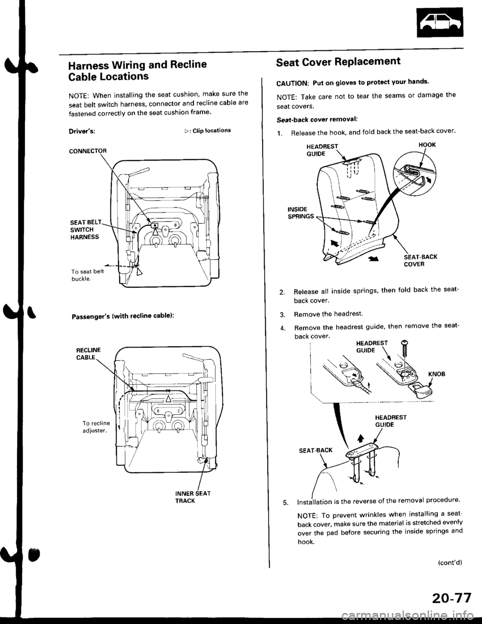
Harness Wiring and Recline
Cable Locations
NOTE: When installing the seat cushion, make sure the
seat belt switch harness, connector and recline cable are
fastened correctly on the seat cushion frame'
Driver's:>: Clip locations
Passenger's (with lecline cablel:
TRACK
Seat Cover RePlacement
CAUTION: Put on gloves to protest yout hands'
NOTE: Take care not to tear the seams or damage the
seat covers.
Seat-back cover removal:
1. Release the hook, and fold back the seat-back cover'
Release all inside springs, then fold back the seat-
back cover.
Remove the headrest.
Remove the headrest guide, then remove the seat-
back cover.
lnst;llation is the reverse of the removal procedure'
NOTE: To prevent wrinkles when installing a seat-
back cover, make sure the material is stretched evenly
over the pad before securing the inside springs and
hook.
3.
(cont'd)
20-77
HEADREST
Page 1317 of 2189
5. Installation is the reverse of the removal procedure.
NOTE:
. Check that the retractor locking mechanism func-
tions as described on page 20-91.
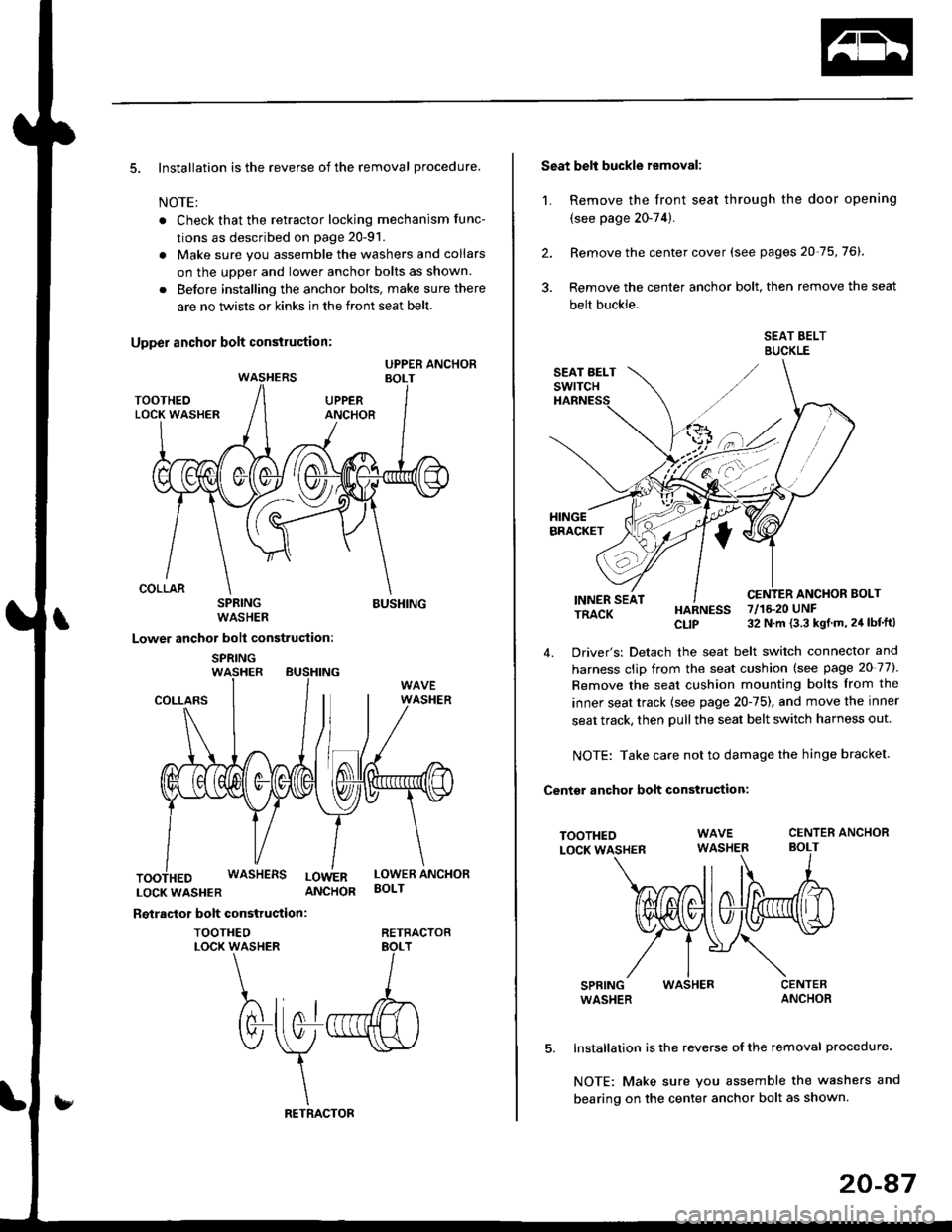
. Make sure you assemble the washers and collars
on the uoDer and lower anchor bolts as shown.
. Before installing the anchor bolts, make sure there
are no twists or kinks in the front seat belt.
SPRINGWASHER
Lower anchor bolt construction:
SPRINGWASHER BUSHING
BUSHING
COLLARS
LOCKWASHER ANCHOR
Reiractor bolt construction:
TOOTHEOLOCK WASHER
WASHERS LowERLOWER ANCHORBOLT
RETRACTOB
Seat belt buckle removal:
1. Remove the front seat through the door opening
{see page 20-74).
2. Remove the center cover (see pages 20-75,76).
3. Remove the center anchor bolt, then remove the seat
belt buckle.
SEAT BELTBUCKLE
ANCHOR BOLTINNER SEATTRACK
TOOTHEOLOCK WASHER
SPRINGWASHER
HARNESS 7/16.20 UNF
CLIP 32 N m (3.3 kgt m, 24 lbf'ft)
4. Driver's: Detach the seat belt switch connector and
harness clip from the seat cushion (see page 20 77).
Remove the seat cushion mounting bolts from the
inner seat track {see page 20-75), and move the inner
seat track, then pull the seat belt switch harness out.
NOTE: Take care not to damage the hinge bracket.
Centsr anchor bolt construction:
CENTER ANCHORBOLT
WASHER
Installation is the reverse of the removal procedure.
NOTE: Make sure you assemble the washers and
bearing on the center anchor bolt as shown.
20-47
Page 1346 of 2189
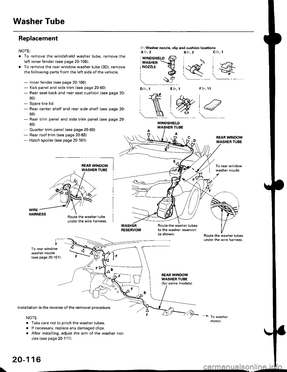
Washer Tube
Replacement
NOTE:
. To remove the windshield washer tube, remove the
left inner fender (see page 20-106),
. To remove the rear window washer tube {3D), remove
the following parts from the left side of the vehicle.
- Inner fender (see page 20-106)- Kick panel and side trim (see page 20-60)- Rear seat-back and rear seat cushion (see page 20-
80)- Spare tire lid- Rear center shelf and rear side shelf (see page 20-
60)- Rear trim panel and side trim panel
60)
Ouarter trim panel (see page 20-60)- Rear roof trim {see page 20-65)- Hatch spoiler (see page 20-101)
(see page 20
WIREHARNESS
>: W.sher nozzle, clip and cushion locationsa>,2B>,3
"J>)
[q@"
F>, 11
c>, 1
wttrtosnteLo 6}usxea =-d
lNozzrE cv
iq
!$e
D>,1 E>, 1
NtW)€
Roote the washer tubeunder the wire harness.
TUBE
A
Route the washer tubesto the washer reservoir
REAB WINDOWWASHER TUBE(Ior some models)
REAR WINDOWWASHER TUBE
washer nozzle.
washer nozzle(see page 20-101).
oo\
Installation is the reverse of the removal procedure.
NOTE:
. Take care not to pinch the washer tubes.
. lf necessary, replace any damaged clips.
. After installing, adjust the aim of the washer noz-
zles (see page 20-117).
20-116
WINDSHIELD
\,--
Page 1358 of 2189
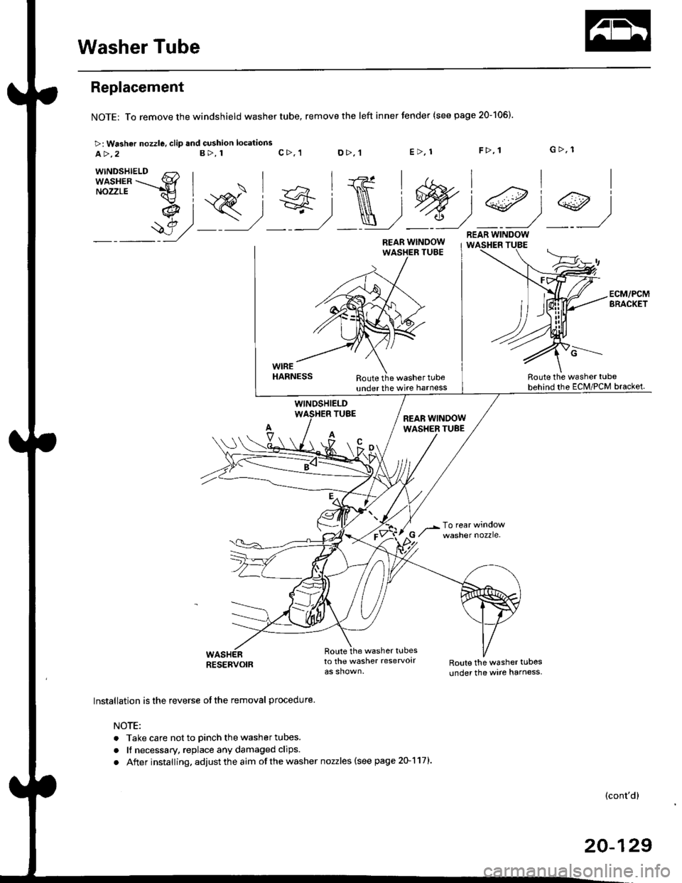
Washer Tube
Replacement
NOTE: To remove the windshield washer tube,
>: Washar nozzle, clip and cushion locations
a>,2B>, 1
remove the left inner fender (see page 20-106).
c>, 1 D>,'tE>, 1F>, 1 G>, 1
n,i#,T
I
9)
ECM/PCMBRACKET
WIREHARNESS
WINOSHIELDTUBE
A
Route the washer tubeunder the wire harnessRoute the washer tube
behind the EcM/PcM bracket.
(cont'd)
RESERVOIR
\/
Route the washer tubesto the washer reservolrRoute the washer tubes
under the wire harness.
Installation is the reverse of the removal procedure.
NOTE:
. Take care not to Dinch the washer tubes.
. lf necessary, replace any damaged clips.
. After installing, adjust the aim of the washer nozzles (see page 20-117l'
c-------.-
REAR WINDOWWASHER TUBE
20-129
Page 1411 of 2189
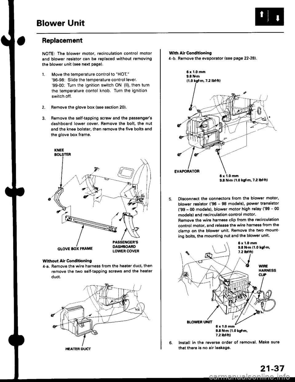
Blower Unit
Replacement
NOTE: The blower motor, recirculation control motor
and blower resistor can bs replacsd without rsmoving
th€ blower unit (see neld Page).
1. Move the temperature control to "HOT."
'96-98: Slide the temperature control lever.'99-00: Turn the ignition switch ON (ll), then turn
the temperature contol knob. Turn the ignition
switch off,
Remove the glovs box (ses ssction 20),
R€move ths s6lf-tapping screw and ths passsng6r's
dashboard low€r cover. Removo the bolt, the nut
and the kn€e bolst€r, then remove the fiv€ bolts and
the glove box trame,
Without Air Condhioning
4-a. Remove the wiro harness from the h68t€r duct, then
remove the two self-tapping scrsws and the heatsr
duct.
KNEE
GLOVE BOX FRAME
HEATER DUCT
21-37
Wrth Air Conditioning
4-b. Removo th6 ev8porator (sss pago 22-28).
6x1.0m|n9.8 N'm
6x1.0mm9.8 N'm lt'o tgf'm, t.2 lb{'ttl
Disconnoct the connectors trom th€ blower motor,
blowor r6sistor {'96 - 98 models), power transiator
('99 - 0O modsls), blowor motor high telay ('99 - 00
models) and recirculation control motor.
R€mov€ ths wiro harnoss clip from tho recirculation
control motor, and release the wir6 harnsss from ths
clamo on the blowor unit. Remove the two mount-
ing bolts, tho mounting nut and ths blowor unit'
9.8 .m 11.0 tgfm,1.2 tblfrl
lnstall in ths reverso order of removal. Mako surs
that thsre is no air leaka96.
6x1.0mm9,t N'm 11.0lgi.m,7.2 tbf.fil
Page 1414 of 2189
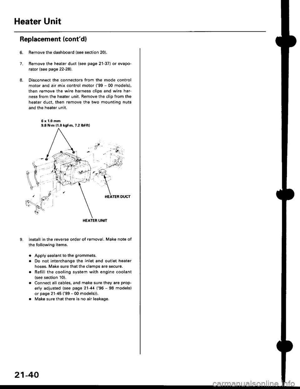
Heater Unit
Replacement (cont'dl
6.
7.
8.
9.
Remove the dashboard (see section 20).
Remove the heater duct (see page 21-37) or evapo-
rator (see page 22-28).
Disconnect the connectors from the mode control
motor and air mix control motor ('99 - 00 models),
then remove the wire harness clips and wire har-
ness from the heater unit. Remove the clip from the
heater duct, then remove the two mounting nuts
and the heater unit.
6x1.0mm9.8 N.m 11.0 kgl.m,7.2 lbf.ftl
HEATER UNIT
lnstall in the reverse order of removal. Make note of
the following items.
Apply sealant to the grommets.
Do not interchange the inlet and outlet heater
hoses. Make sure that the clamps are secure.
Refill the cooling system with engine coolant
(see section 10).
Connect all cables, and make sure they are prop-
erly adjusted (see page 21-44 (96 - 98 models)
or page 21-45 ('99 - 00 models)).
Make sure that there is no air leakage.
21-40
Page 1422 of 2189
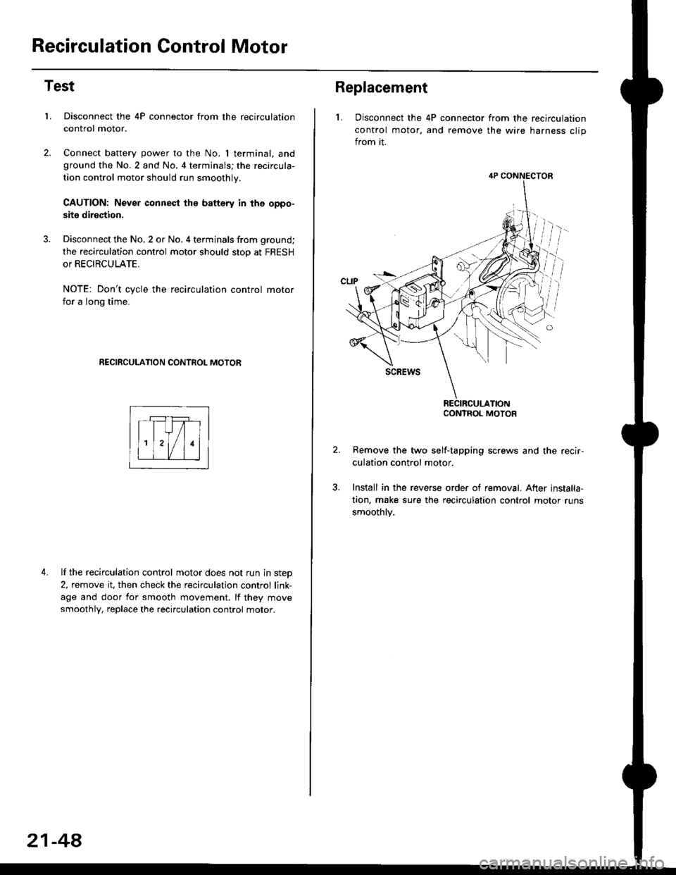
Recirculation Control Motor
Test
LDisconnect the 4P connector from the recirculation
control motor.
Connect battery power to the No. I terminal, andground the No.2 and No. 4 terminals; the recircula-
tion control motor should run smoothly.
CAUTION: Never connest ths battery in the oppo-
site direction.
Disconnect the No. 2 or No. 4 terminals from ground;
the recirculation control motor should stop at FRESH
or RECIRCULATE.
NOTE: Don't cycle the recirculation control motor
for a long time.
RECIRCULATION CONTROL MOTOR
4. lf the recirculation control motor does not run in step
2, remove it, then check the recirculation control link-
age and door for smooth movement. lf they move
smoothly, replace the recirculation control motor.
21-48
Replacement
L Disconnect the 4P connector from the recirculation
control motor, and remove the wire harness clip
from it.
Remove the two self-tapping screws and the recir-
culation control motor.
Install in the reverse order of removal. After installa,
tion, make sure the recirculation control motor runs
smoothly.
4P CONNECTOR
CONTROL MOTOR