HONDA CIVIC 2000 6.G Workshop Manual
Manufacturer: HONDA, Model Year: 2000, Model line: CIVIC, Model: HONDA CIVIC 2000 6.GPages: 2189, PDF Size: 69.39 MB
Page 141 of 2189
Cylinder HeadRocker Arms
18.
19.
21.
22.
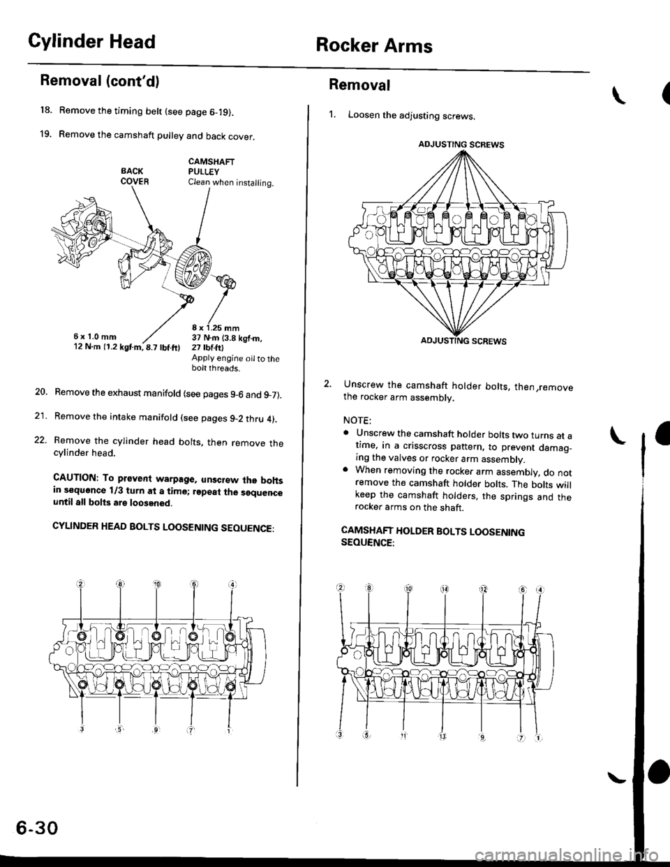
Removal (cont'd)
Remove the timing belt {see page 6-19).
Remove the camshaft pulley and back cover,
CAMSHAFTPULLEYClean when installing.
6x1.0mm8 x 1.25 mm37 N.m (3.8 kgf.m,21 tbtlrlApply engine oilto thebolt threads.
Remove the exhaust manifold {see pages 9-6 and 9_7).
Remove the intake manifold (see pages 9-2 thru 4).
Remove the cylinder head bolts, then remove thecylinder head.
CAUTION: To pr€vent warpage, unsclew lhe bohsin sequonce 1/3 turn at a time; rgpeat tho sequenceuntil all bolts are loosened.
CYLINDER HEAD BOLTS LOOSENING SEOUENGE:
6-30
Removal
1. Loosen the adjusting screws.
2. Unscrew the camshaft holder bolts, then,removethe rocker arm assembly.
NOTE:
a Unscrew the camshaft holder bolts two turns at at,me, in a crisscross pattern, to prevent damao_ing the valves or rocker arm assembly.. When removing the rocker arm assembly, do notremove the camshaft holder bolts. The bolts willkeep the camshaft holders, the springs and therocker arms on the shaft.
CAMSHAFT HOLDER BOLTS LOOSENINGSEOUENCE:
\(
ADJUSTING SCREWS
Page 142 of 2189
Disassembly/Reassembly
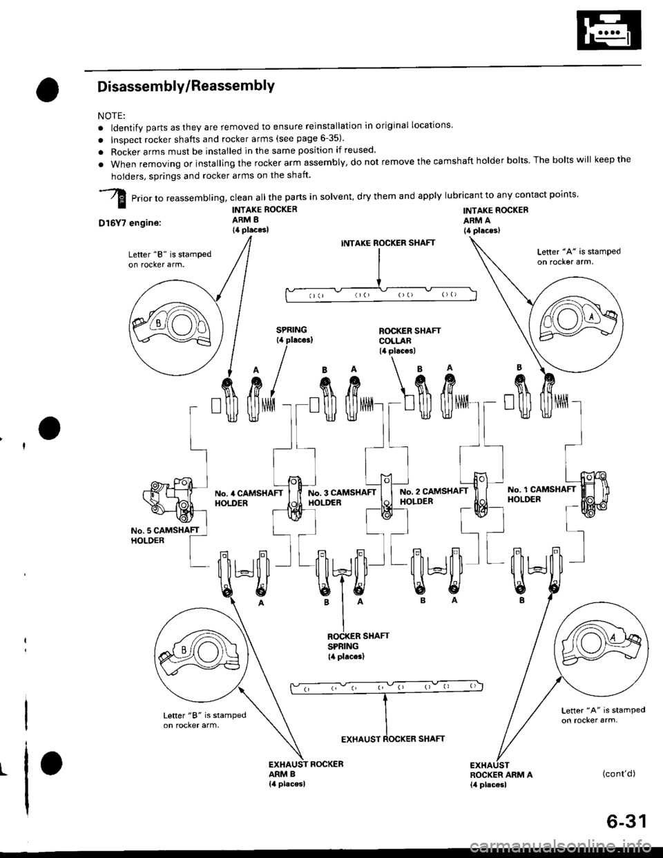
NOTE:
. ldentify parts as they are removed to ensure reinstallation in original locations'
. lnsDect rocker shafts and rocker arms (see page 6-35).
. Rocker arms must be installed in the same position if reused.
. when removing orinstallingthe rocker arm assembly,donot remove the camshaft holder bolts. The boltswill keepthe
holders, springs and rocker arms on the shaft.
-Zl prio, ,o reassemblinq, clean all the pans in solvent, dry them and apply lubricant to any contact points.
| - TNTAKE RocKER TNTAKE RocKER
D16Y7 engine:
Lefter "8" is stampedon rocker arm.
ARM A(4 placeslARM B
14 places)
INTAXE
ROCKER SHAFTSPRING{4 places)
ROCKER SHAFTCOLLAR14 plac.3l
ROCKER
I
II
I
BA\'A
fift L$\ft
:oo)[*o:
llll.I Jol----tNo.3 CAMSHAFT | | ruo. z cltusxerr 1i
T-* l=Bl-* d
,", 'l l=^ ^l
qJ?[l'-qJ'Ll
'I^ B A
EI
[ilHl"\9
t(cont'd)
6-31
Page 143 of 2189
Rocker Arms
Disassembly/Reassembly (cont'dl
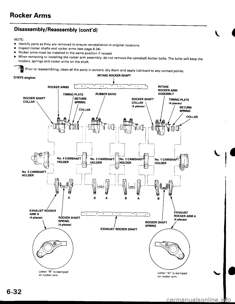
NOTE:
. ldentify pans as they are removed to ensure reinstallation in original locations.. Inspect rocker shafts and rocker arms (see page 6-34).. Rocker arms must be installed in the same position if reused.t when removing or installing the rockerarm assembly, do not remove the camshaft holder bolts. The boltswill keeptheholders, springs and rocker arms on the shaft.
I erior to reassembring, crean a
the parts in sorvent, dry them and appry rubricant to any contact points.
D16Y5 engine:
ROCKER ARMS
TIMING PLATERUBBER BANO
(\
-]-
-P'g,rpt+.t't ll
\--,?|, -\2i lNo.5 CAMSHAFT _ lHOLDER l
No. 4 CAMSHAFTHOLDERNo. 3 CAMSHAFIHOLDERNo.2HOLDER
ra
I
EXHAUST ROCKERARM B{,1 plac€s)
EXHAUST ROCKEE SHAFT
Letter "A" is slamped
II{TAKE ROCKER SHAFT
!-r I
?h'ffi*ffi'
/^ ---IOCKER SHAFT
Letter "8" is stamped
6-32
Page 144 of 2189
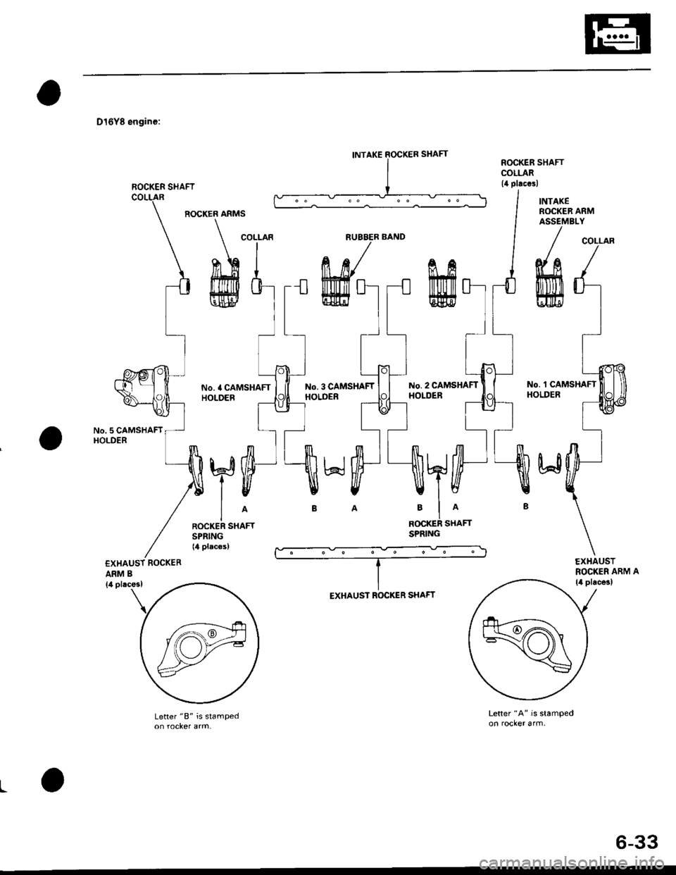
D16Y8 engine:
No. 5 CAMSHAFTHOLDER
ARM B
ROCKER ARMS
No. 4 CAMSHAFTHOLOER
No. 3 CAMSHAFTHOLDER
No. 2 CAMSHAFTHOLDER
No. 'l CAMSHAFTHOLDER
R(rcKER SHAFTSPRING
Letter "B" is stampedLetter "A" is stamped
L
INTAKE SOCKER SHAFT
ROCKER SI{AFT
COLLARNUBBER BANDCOLLAR
EXHAUST ROCKER SHAFT
6-33
Page 145 of 2189
Rocker Arms and Lost Motion Assemblies
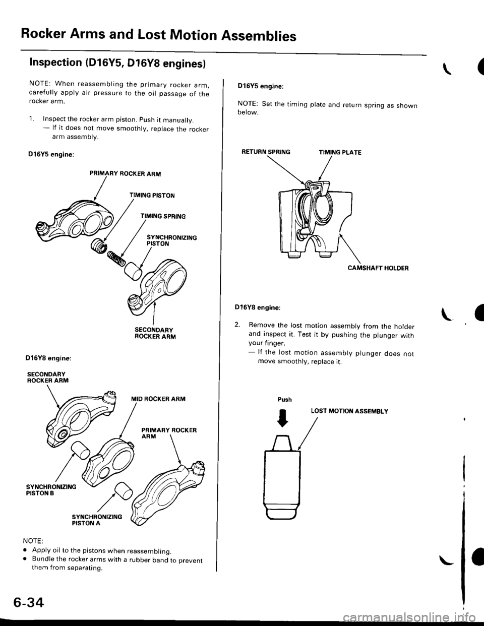
Inspection (D16Y5, Dt6Y8 enginesl
NOTEr When reassembling the primary rocker arm,carefully apply air pressure to the oil passage of therocker arm.
1. Inspect the rocker arm piston. push it manually.- lf it does not move smoothly, replace the rockerarm assembty.
Dl6Y5 engine:
ROCKER ARM
TIMING PISTON
TIMING SPRING
SYNCHRONTZINGPISTON
SECONDARYROCKER ARM
MID ROCKER ARM
PRIMARY ROCKER
SYNCHRONIZINGPISTON A
NOTE:
. Apply oil to the pistons when reassembling.o Bundle the rocker arms with a rubber band to preventthem from separating.
6-34
(\
DI6YS engine:
NOTE: Set the timing plate and return spring as shownoerow.
RETURN
CAMSHAFT HOLDER
Dl6Yg engine:
2. Remove the lost motion assembly from the holderand inspect it. Test it by pushing the plunger withyour finger.- lf the lost motion assembly plunger does notmove smoothly, replace it.
LOST MOTION ASSEMBLY
\a
Pu3h
I
Page 146 of 2189
Rocker Arms and Shafts
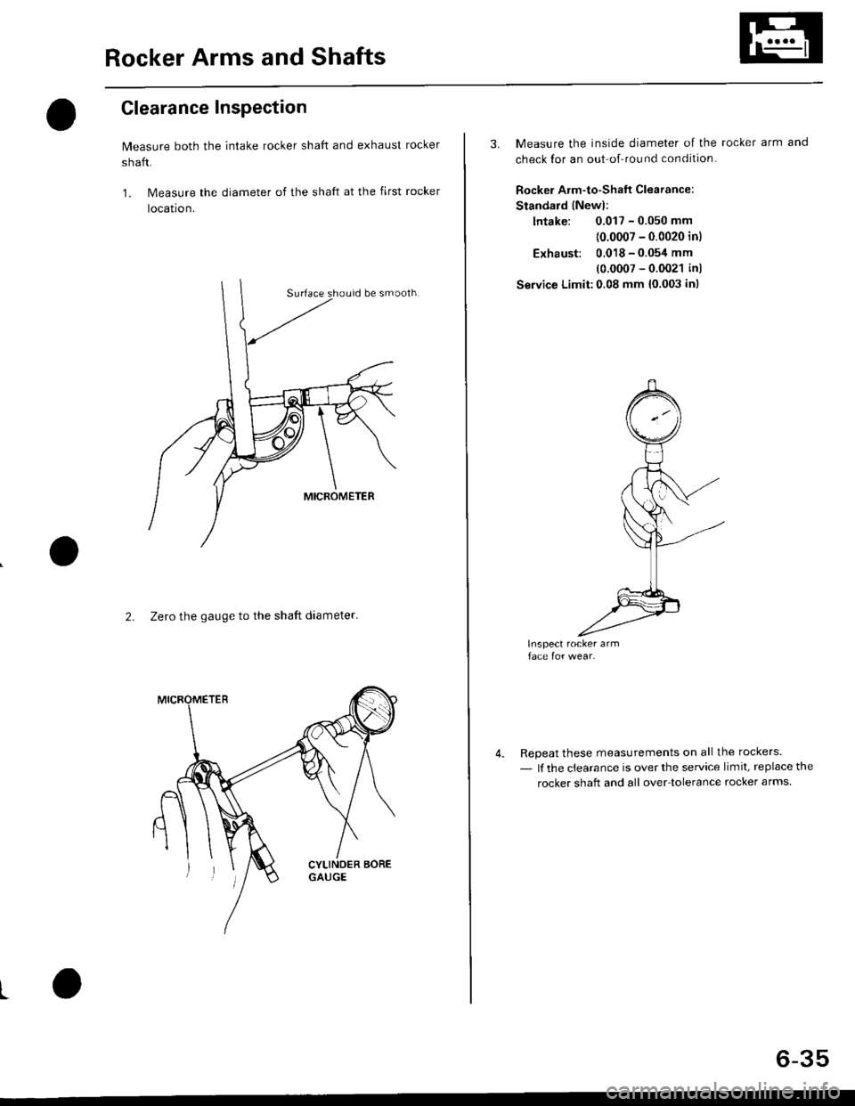
Clearance Inspection
Measure both the intake rocker shaft and exhaust rocker
shaft.
1. Measure the diameter of the shaft at the first rocker
locatron.
2. Zero the gauge to the shaft diameter'
I
3. Measure the inside diameter of the rocker arm and
check for an out of-round condition.
Rockel Arm-to-Shaft Clearance
Standard (Newl:
lntake: 0.017 - 0.050 mm
{0.0007 - 0.0020 inl
Exhaust: 0.018 - 0.054 mm
(0 0007 - 0 0021 in)
Service Limit:0.08 mm {0.003 inl
Repeat these measurements on all the rockers.
- lf the clearance is over the service limit, replace the
rocker shaft and all over tolerance rocker arms.
6-35
Page 147 of 2189
Gamshaft
Inspection
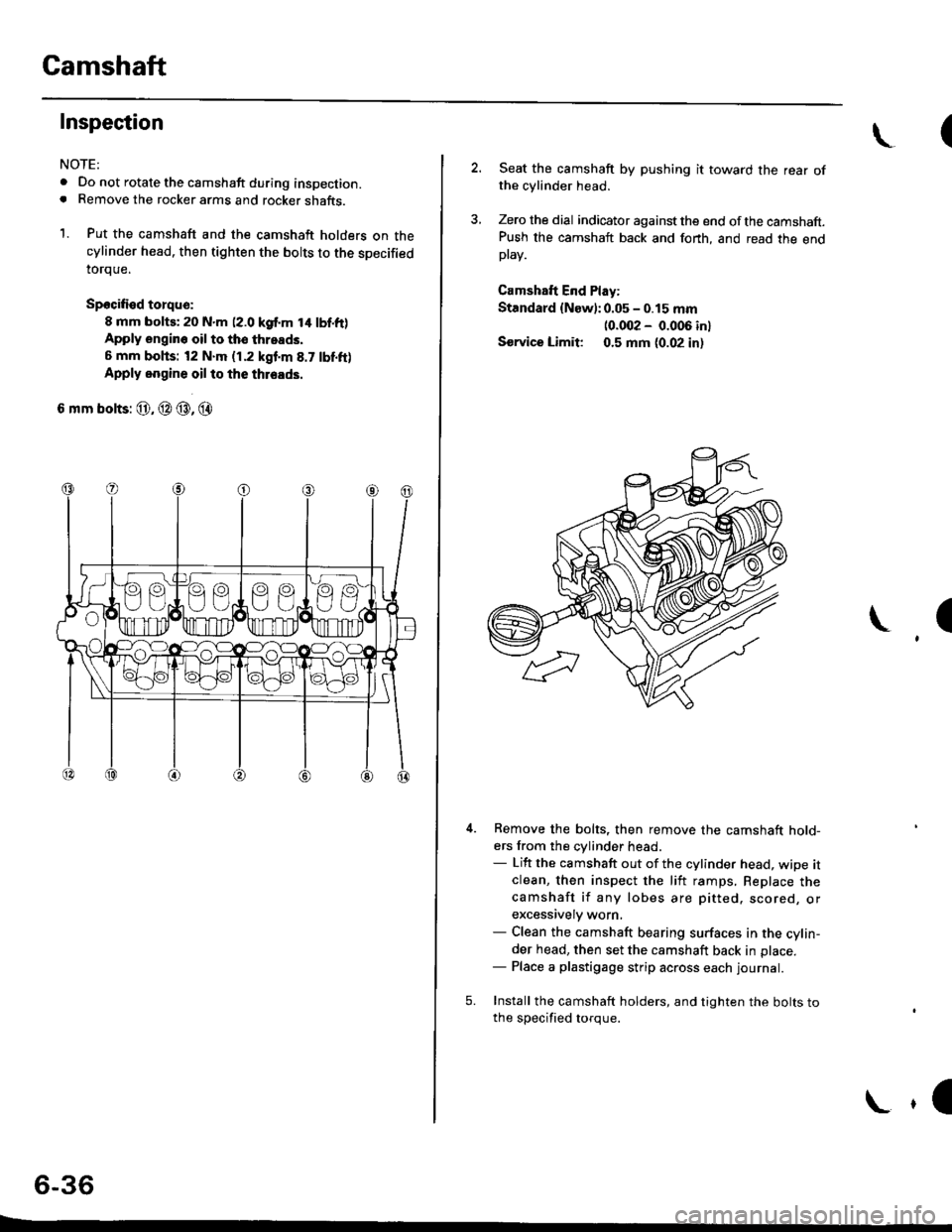
NOTE:
. Do not rotate the camshaft during inspection.. Remove the rocker arms and rocker shafts.
1. Put the camshaft and the camshaft holders on thecylinder head. then tighten the bolts to the specified
toroue.
Spocified torqu€:
8 mm bolts; 20 N.m (2.0 kgf.m t4 lbf.ft)Apply engin6 oil to tho throads,
6 mm bohs: t2 N.m (1.2 kgf'm 8.7 tbf.ft)
Apply oogine oil to the thleads.
6 mm bolts: @, @ @, @
6-36
E
\(
2. Seat the camshaft by pushing it toward the rear ofthe cylinder head.
3, Zero the dial indicator against the end ofthe camshaft.Push the camshaft back and fonh, and read the endptav.
Camshaft End Play:
Standard {New):0.05 - 0.15 mm
10.002 - 0.006 inl
Sorvice Limit 0.5 mm (0.02 in,
I
5.
Remove the bolts, then remove the camshaft hold-ers from the cylinder head.- Lift the camshaft out of the cylinder head, wipe itclean, then inspect the liit ramps, Replace thecamshaft if any lobes are pitted. scored, orexcessively worn,- Clean the camshaft bearing surfaces in the cylin-der head, then set the camshaft back in place.- Place a plastigage strip across each Iournal.
Install the camshaft holders, and tighten the bolts tothe soecified toroue.
\,l
Page 148 of 2189
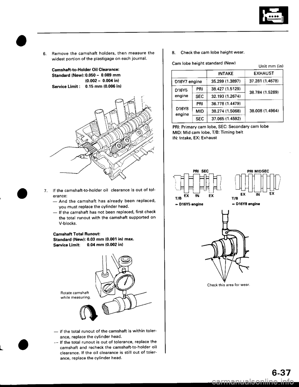
6, Remove the camshaft holders. then measure the
widest ponion of the plastigage on each journal.
Camshaft-to-Holder Oil Clearance:
Standard lNew):0.050 - 0.08!t mm
{0.002 - 0.004 in}
Service Limit : 0.15 mm {0.006 in)
lf the camshaft-to-holder oil clearance is out ot tol-
erance:- And the camshaft has already been replaced,
you must replace the cylinder head.
- lf the camshaft has not been replaced, first check
the total runout with the camshaft supported on
V-blocks.
Camshaft Total Runout:
Standard (New): 0.03 mm (0.001 inl max.
Service Limit: 0.04 mm {0.(X)2 in)
-7.
Rotate camshattwhile measuring.
L
- lf the total runout of the camshaft is within toler-
ance, replace the cylinder head.
- lf the total runout is out of tolerance, replace the
camshaft and recheck the camshaft-to-holder oil
clearance. lf the oil clearance is still out of toler-
ance. replace the cylinder head.
INTAKEEXHAUST
O16Y/ engine35.299 (1.3897)37.281 (1.4678)
D16Y5
engrne
PRI38.427 11.5129138.784 (1.5269)
SEC32.193 (1.2674)
D l6Y8
engrne
PRI36.77811.44791
38.008 (1.4964)MID38.274 (1.5068)
sEu37.065 (1.4592)
8. Check the cam lobe height wear.
Cam lobe height standard (New)
t/g a* rN Ex
- D16Y5 engine
PRI; Primary cam lobe, SEC: Secondary cam lobe
MtD: Mid cam lobe. T/B: Timing belt
lN: Intake, EX: Exhaust
PRIsEcMIDSEC
rts
- Dl6YE ongine
Unit mm (in)
Check this area {or wear.
6-37
Page 149 of 2189
Valves, Valve Springs and Valve Seals
Removal
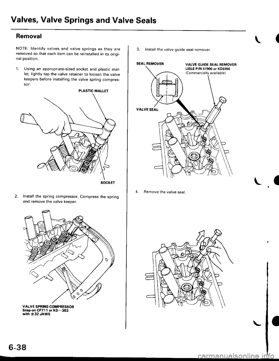
NOTE: ldentify valves and valve springs as they areremoved so that each item can be reinstalled in its orioi-nal oosition.
'1. Using an appropriate-sized socket and plastic mal-let. lightly tap the valve retainer to loosen the valve
keepers before installing the valve spring compres-
sor.
Install the spring compressor. Compress the spring
and remove the valve keeper.
PLASTIC MALLET
SOCKET
VALVE SPRII{G COMPRESSORSnlp-on CF711 or KD-383whh #32 JAWS
6-38
L
(
3. Install the valve guide seal remover.
SEAL REMOVER vat vF GI nF !
4. Remove the valve seal.
I
VALVE GUIDE SEAL REMOVERLISLE P/N 57900 or KD3350
Page 150 of 2189
Valve Guides
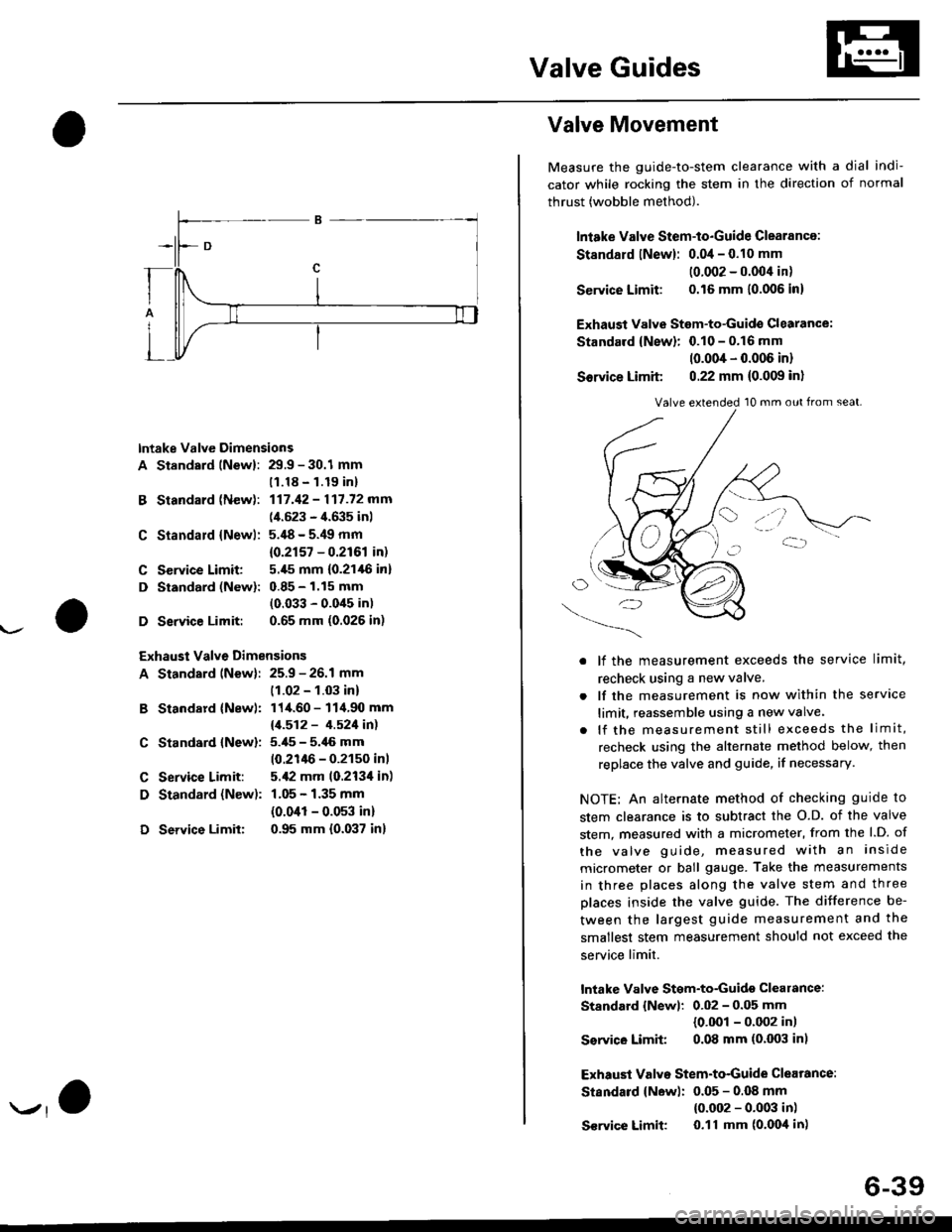
lntake Valve Dimensions
A Standsrd lNewl: 29.9 - 30.1 mm
B Standard (New):
C Standald {Newl:
C Service Limit:
D Standard (New):
D Service Limit:
11.18 - 1.19 inl
117.42 - 117.72 mm
(4.523 - 4.635 inl
5.'18 - 5.49 mm
{0.2r57 - 0.2r61 in)
5.,[5 mm (0.21,16 in]
0.85 - 1.15 mm
(0.033 - 0.0'15 in)
0.65 mm (0.026 in)
Exhaust Valve Dimensions
A Standard lNew): 25.9 - 26.1 mm
B Standard {Newl:
C Standard {New):
C Service Limit:
D Standard {New):
D Service Limit:
(1.02 - 1.03 in)
114.60 - 114.90 mm
11.512 - 4.521in1
5.i[5 - 5.46 mm
10.21lt6 - 0.2150 inl
5.,12 mm 10.213'l in)
1.05 - 1.35 mm
{0.041 - 0.053 in)
0.95 mm {0.037 in}
Valve Movement
Measure the guide-to-stem clearance with a dial indi-
cator while rocking the stem in the direction of normal
thrust (wobble method).
lniake Valve Stem-to-Guide Clearance:
St8ndard lNew): 0.04 - 0.10 mm
10.002 - 0.004 in)
Service Limit: 0.16 mm 10.006 in)
Exhaust Valvs Stem-to-Guide Glearance:
Standard {New}: 0.10 - 0.16 mm
10.004 - 0.006 in)
Sorvice Limit 0.22 mm (0.009 in)
O/'-_)
. lf the measurement exceeds the service limit,
recheck using a new valve.
. lf the measurement is now within the service
limit, reassemble using a new valve.
. lf the measurement still exceeds the limit,
recheck using the alternate method below, then
replace the valve and guide, if necessary.
NOTE: An alternate method of checking guide to
stem clearance is to subtract the O.D. of the valve
stem, measured with a micrometer, from the l.D. of
the valve guide, measured with an inside
micrometer or ball gauge. Take the measurements
in three places along the valve stem and three
places inside the valve guide. The difference be-
tween the largest guide measurement and the
smallest stem measurement should not exceed the
service limit.
lntake Valve Stgm-to-Guidg clearance:
Standard {Newl: 0.02 - 0.05 mm
{0.001 - 0.002 in)
Ssrvico Limit 0.08 mm (0.003 in)
Exhaust Valvo Stem-to-Guide Clearance:
Standard {New): 0.05 - 0.OB mm
{0.002 - 0.003 in)
S€rvice Limit 0.11 mm (o'Ooil in)
Valve extended 10 mm out from seat.
6-39