light HONDA CIVIC 2000 6.G Workshop Manual
[x] Cancel search | Manufacturer: HONDA, Model Year: 2000, Model line: CIVIC, Model: HONDA CIVIC 2000 6.GPages: 2189, PDF Size: 69.39 MB
Page 1045 of 2189
Driveshafts
Reassembly (cont'dl
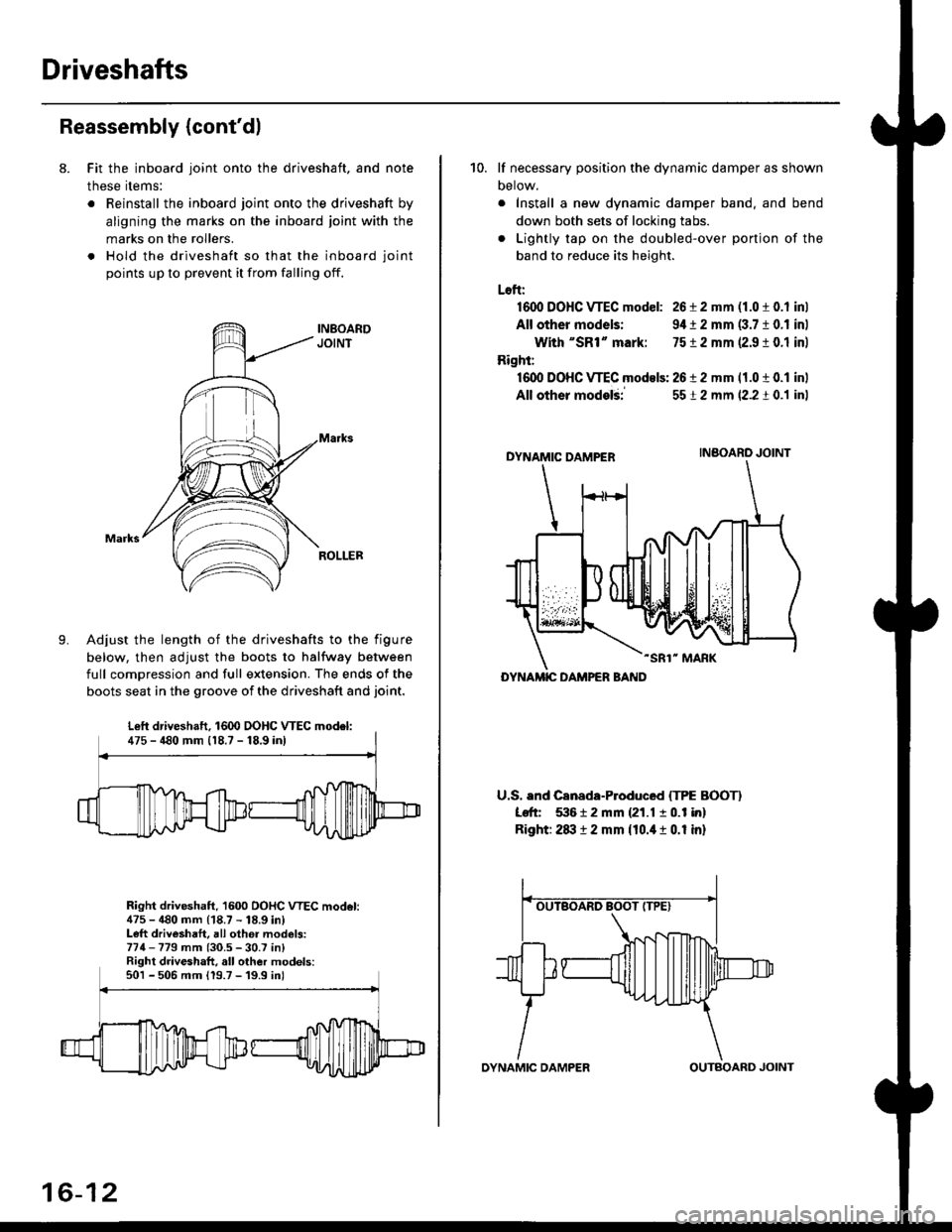
8. Fit the inboard joint onto the driveshaft, and note
these items:
. Reinstall the inboard joint onto the driveshaft by
aligning the marks on the inboard joint with the
marks on the rollers.
. Hold the driveshaft so that the inboard joint
points up to prevent it from falling off.
Adjust the length of the driveshafts to the figure
below, then adjust the boots to halfway between
full comDression and full extension. The ends of the
boots seat in the groove of the driveshaft and joint.
Right driveshaft, 1600 OOHC VTEC model:475 - 480 mm (18.7 - 18.9 in)Left driveshaft, all othei models:774-779 mm (30.5 - 30.7 in)Right driveshaft, all other models:501 - 506 mm 119.7 -'19.9 inl
Left driveshaft. 1600 DOHC WEC model:475 - 480 mm 118.7 - 18,9 inl
16-12
OYNAMIC DAMPEROUTBOARD JOINT
10. lf necessary position the dynamic damper as shown
Detow.
. Install a new dynamic damper band. and bend
down both sets of locking tabs.
. Lightly tap on the doubled-over ponjon of the
band to reduce its height.
Loft:
1600 DOHC VTEC model: 26 i 2 mm (1.0 t 0.1 inl
All other models: 9,1t 2 mm (3.7 10.1 inl
With "SR1" mark: 7512 mm 12.9 ! 0.1 inl
Right:
16dl DOHC VTEC models: 2612 mm 11.0 t 0.1 inl
All other modelii
DYNAMIC DAMPER
-SR1" MARK
U.S. and Canada-Produced ITPE BOOTI
Left 53612 mm {21.1 10.1 in}
Right: 2txt 12 mm {10.it 1 0.1 in}
5512 mm (2.2 t 0.1 inl
INBOARO JOINT
DYNAMIC DAMPER BAND
Page 1067 of 2189
It
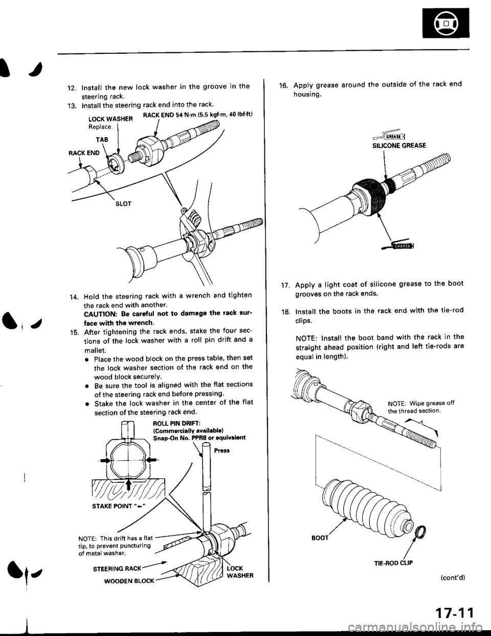
12.
13.
lnstall the new lock washer in the groove in the
steering rack.
Installthe steering rack end into the rack
LOCK WASHER RACK END 54 N m ts.s kgf'm, 40 lbtft)
Replace.
TAB
(l*v
14.
15.
RACK END
Hold the steering rack with a wrench and tighten
the rack end with another.
CAUTION: Be careful not to damage the tack sur-
fac€ with the wrench.
After tightening the rack ends, stake the four sec-
tions of the lock washer with a roll pin drift and a
mallet.
. Place the wood block on the press table. then set
the lock washer section of the rack end on the
wood block securelY.
. Be sure the tool is aligned with the flat sections
of the steering rack end before pressing
. Stake the lock washer in the center of the flat
section of the steering rack end.
ROLL PIN DnlFTl(Commorci.lly .Yril.blolSnap-On No. PPRS or oquival.nt
NOTE: This drift has a flat
tip, to prevent puncturing
of metal washer.
srEEatruG nlCr/rl,WOODEN BLOCK
TIE.ROO CLIP
16. Apply grease around the outside ot the rack end
housing.
Apply a light coat of silicone grease to the boot
grooves on the rack ends.
lnstall the boots in the rack end with the tie-rod
clips.
NOTE: Install the boot band with the rack in the
straight ahead position (right and left tie-rods are
equal in length).
=-..r=-q!q!!.n
SILICONE GREASE
17.
(cont'd)
17-11
NOTE| WiPe grease off
the thread sectlon
Page 1068 of 2189
Steering Gearbox
Reassembly (cont'd)
21.
'19.
20.
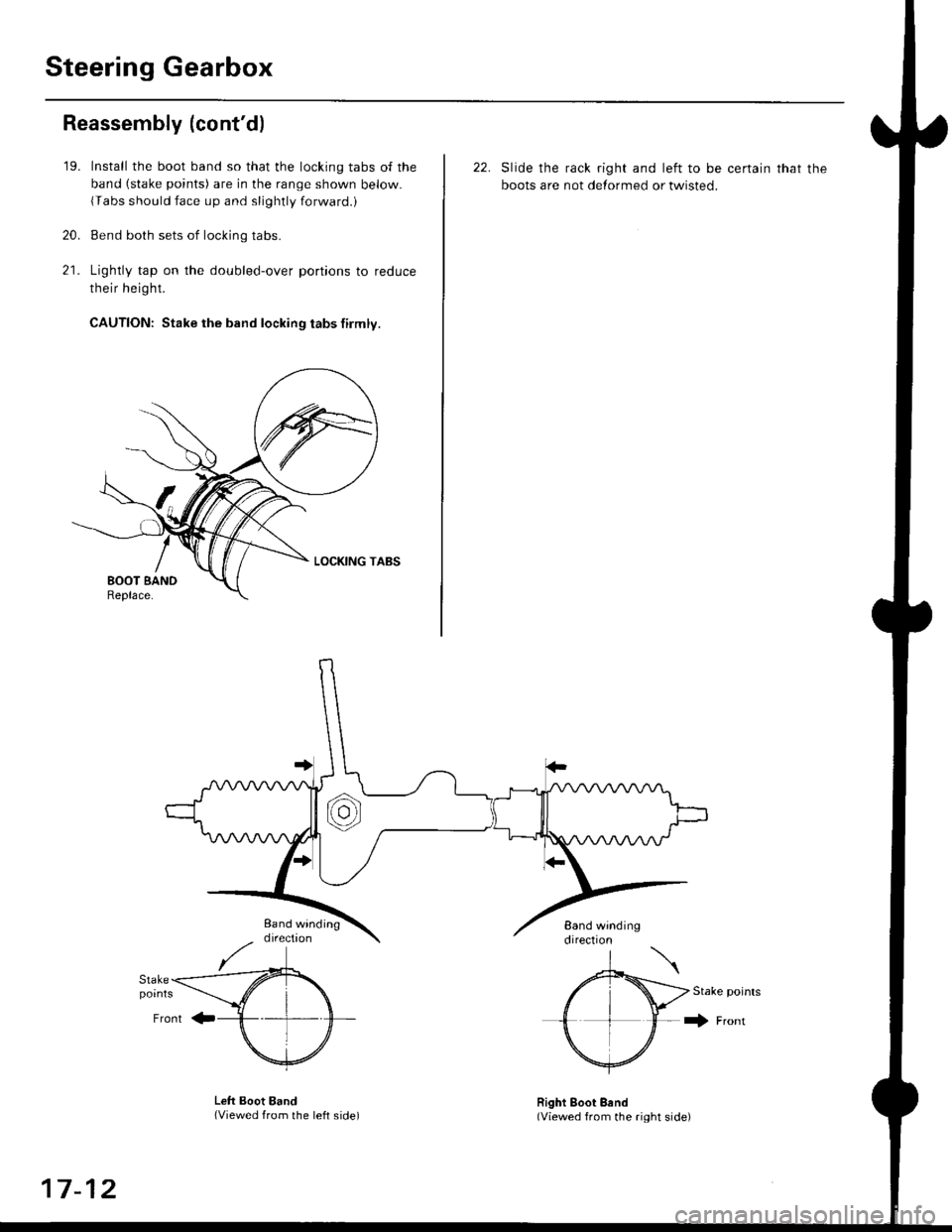
Install the boot band so that the locking tabs of the
band (stake points) are in the range shown below.
{Tabs should face up and slightly forwaro.,
Bend both sets of locking tabs.
Lightly tap on the doubled-over portions to reduce
their height.
CAUTION: Stake the band locking tabs firmly.
22. Slide the rack right and left to be certain that the
boots are not detormed or twisted.
Stake points
+ Fronr
Lett Boot Band(Viewed from the left side)Right Boot Bend(Viewed from the right side)
17-12
Page 1077 of 2189
Pressure Control
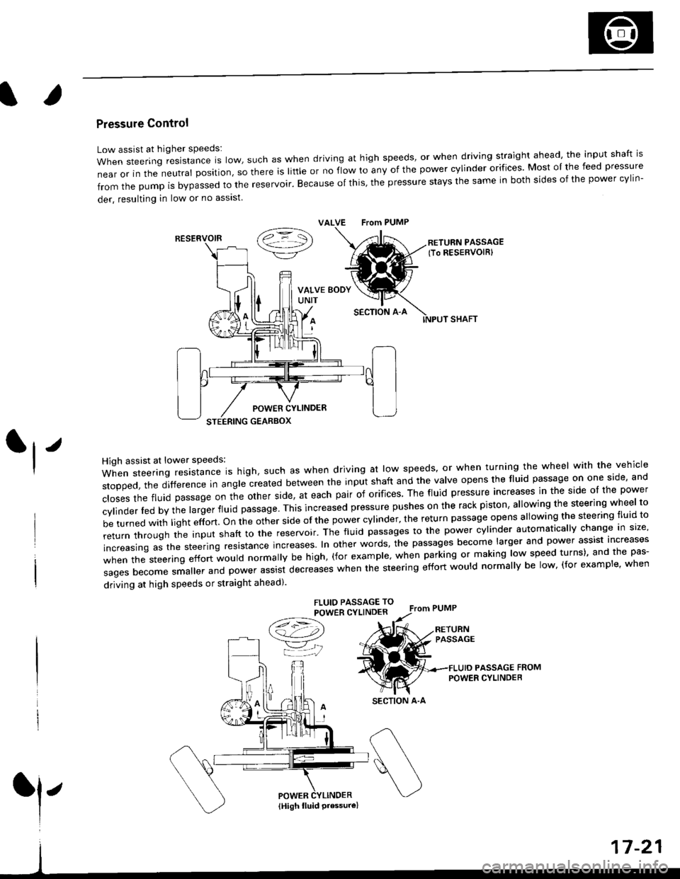
Low assist at higher speeds:
WhensteeringresistanceIsIow,suchaswhendrivingathighspeeds,orwhendrivingstraightahead,theinputshaftis
near or in the neutral position, so there is little or no fiow ro any of the power cylinder orifices. Most oI the feed pressure
fromthepumpisbypassedtothereservoir.Becauseofthis,thepressurestaysthesameinbothsidesofthepowercy||n-
der, resulting in low or no asslst
VALVE From PUMP
SECTION A-A
RETURN PASSAGElTo RESERVOIRI
POWER CYLINDER
STEERING GEARBOX
High assist at lower speeds:
When steering resistance is high. such as when driving at low speeds' or when turning the wheel wirh the vehicle
stopped,thedifference|nang|ecreatedbetweentheinputshaftandtheVa|veopensthef|uidpassageononeside,and
c|osesthefluidpassageontheotherside,ateachpairoforifices'Thef|uidpressureincreasesinthesideo|thepower
cy|inder|edbythe|argerf|uidpassage'Thisincreasedpressurepushesontherackpiston,a|lowingthesteeringwhee|to
be turned with light effort. on the other side of the power cylinder, the return passage opens allowing the steering tluid to
returnthroUghtheinputshafttothereservoir'Thef|uidpassagestothepowercy|inderautomatica||ychangeins|ze,
increasing as the steering resrstance increases. In other words, the passages become larger and power assist increases
when the steering effort would normally be high, (for example' when parking or making low speed turns)' and the pas-
sagesbecomesma||erandpowerassistdecreaseswhenthesteeringeffortwou|dnorma||ybe|ow,(forexamp|e,when
driving at high speeds or straight ahead).
FLUIO PASSAGE TO
POWER CYLINDER
/t=\\a!-4,))
=YjJ
RESERVOIR
SECTION A-A
l'
{High fluid Pressure}
Page 1080 of 2189
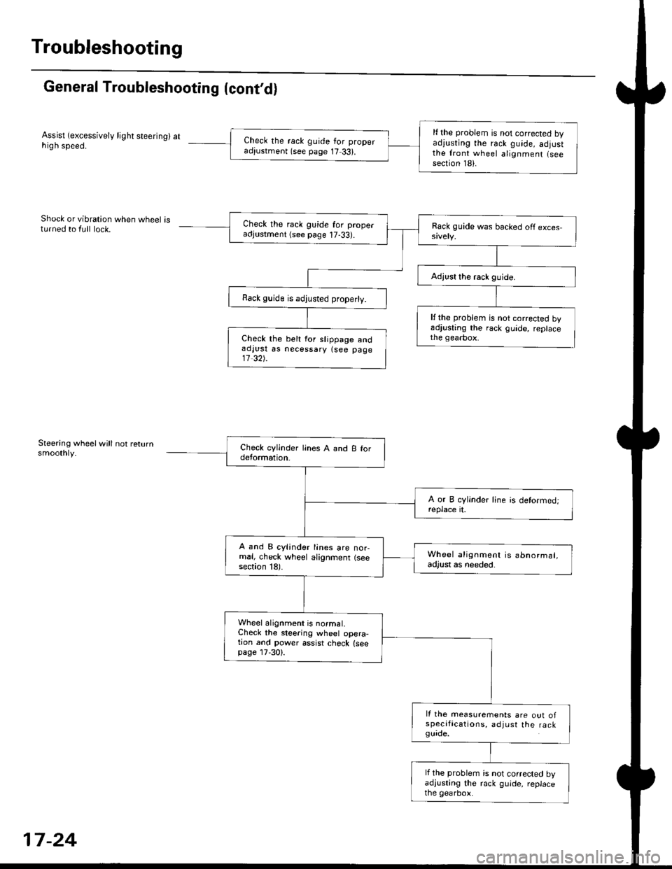
Troubleshooting
General Troubleshooting (cont'd)
Assist (excessively light steering) athigh speed.
Shock or vibration when wheel isturned to {ull lock.
Steering wheelwill not returnsmoothly.
lf the problem is not corrected byadiusting the rack guide, adjustthe front wheel alignment lseesection 181.
Check the rack guide for properadiustment (see page 17 33).
Check the rack guide for properadjustment (see page 17-33).
Rack guide is adjusted properly.
lfthe problem is not corrected byadjusting the rack guide, replacethe gearbox.Check the belt for slippage andaolust as necessary {see page11 32).
A and B cylinder lines are nor-mal, check wheel alignment (seesection 18).
Wheel alignment is abnormal,adjust as needed.
Wheel alignment is normal.Check the steering wheel opera-tion and power assist check {seepage lT-30).
It the measurements are out ofspecifications, adjust the ra ckguide.
lf the problem is not corrected byadjusting the rack guide, replacethe gearbox.
17-24
Page 1091 of 2189
Steering Wheel
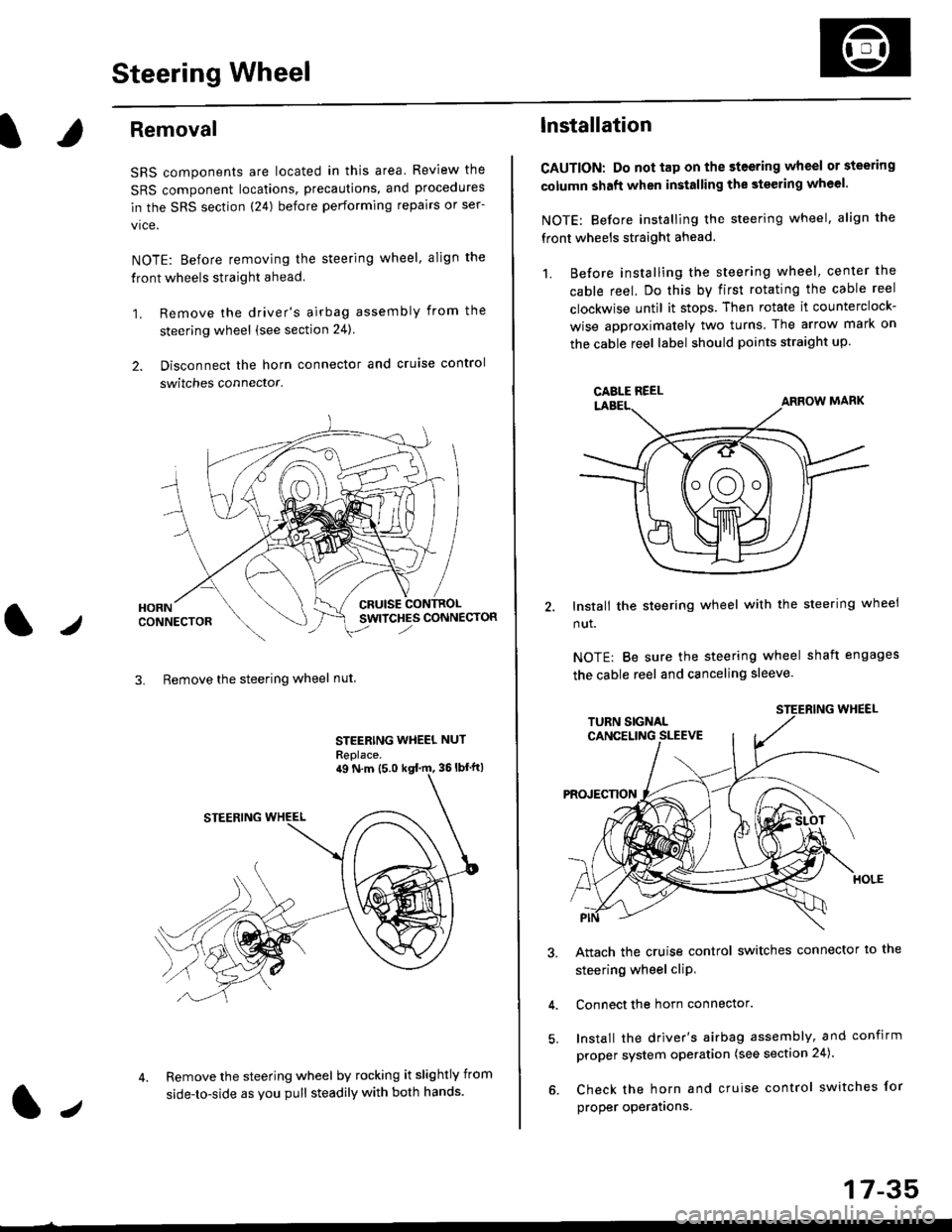
l,/
Removal
SRS components are located in this area Review the
SRS component locations, precautions, and procedures
in the SRS section (24) before performing repairs or ser-
vice.
NOTE: Before removing the steering wheel. align the
front wheels straight ahead.
1. Remove the driver's airbag assembly from the
steering wheel (see section 24)
2. Disconnect the horn connector and cruise control
switches connector.
CRUISESWITCHES CONNECTOR
3. Remove the steering wheel nut
STEERING WHEEL NUT
Replace.
Remove the steering wheel by rocking it slightly from
side-to-side as you pull steadily with both hands.
ag N.m {5.0 kgt rn, 36lbfft)
1.,
17-35
lnstallation
CAUTION: Do not tap on the steering wheel or steering
column shaft when installing the stsering wheel.
NOTE: Before installing the steering wheel, align the
front wheels straight ahead.
1. Before installing the steering wheel, center the
cable reel, Do this by first rotating the cable reel
clockwise until it stops. Then rotate it counterclock-
wise approximately two turns The arrow mark on
the cable reel label should points straight up.
Install the steering wheel with the steering wheel
nut.
NOTE: Be sure the steering wheel shaft engages
the cable reel and canceling sleeve.
Attach the cruise control switches connector io the
steering wheel cliP,
Connect the horn connector.
Install the driver's airbag assembly, and confirm
proper system operation (see section 24).
Check the horn and cruise control switches for
proper operatrons.
CAELE REEL
Page 1120 of 2189
Steering Gearbox
Reassembly (cont'dl
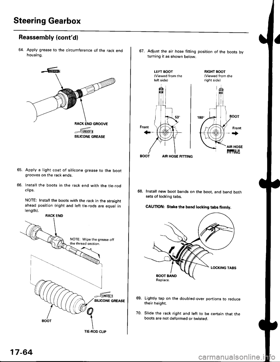
64. Apply grease to the circumference of the rack endhousing.
RACK END GROOVE
=^.#-q!:s!!H
SILICONE GREASE
Apply a light coat of silicone grease to the bootgrooves on the rack ends.
lnstall the boots in the rack end with the tie-rodclips.
NOTE: Install the boots with the rack in the straightahead position (right and left tie-rods are equal inlength).
66.
RACK END
NOTE: Wipe the grease offthe thread section.
17-64
TIE.ROD CLIP
67. Adjust the air hose fitting position of the boots bvturning it as shown below.
LEFT BOOT(Viewed from theleft side)
RIGHT BOOT{Viewed from theright side)
AIR HOSE FITTING
Install new boot bands on the boot, and bend bothsets of locking tabs.
CAUTION: Stlke ths band locking tabs firmly.
Lightly tap on the doubled-over portions to reducetheir height.
Slide the rack right and left to be certain that theboots are not deformed or twisted.
Page 1135 of 2189
)
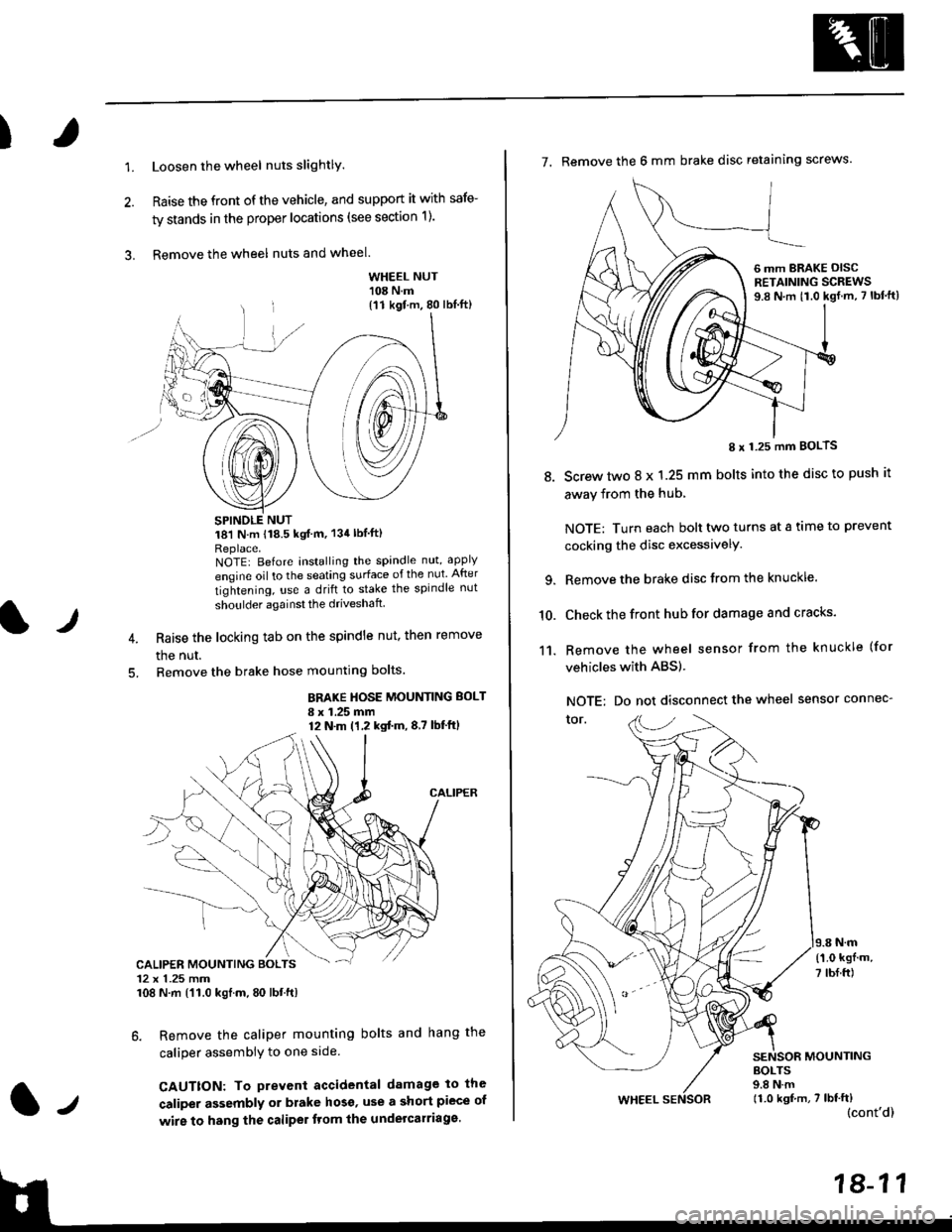
1.Loosen the wheel nuts slightlY.
Raise the front of the vehicle, and support it with safe-
ty stands in the proper locations (see section 1).
Remove the wheel nuts and wheel.3.
l)
WHEEL NUT'108 N.m
18'l N.m 118.5 kgf m, 134lblfti
Replace.NOTEI Before installing the spandle nut, apply
engine oil to the seating surface of the nut After
tightening, use a drift to stake the spindle nut
shoulder againsl the driveshaft
Raise the locking tab on the spindle nut, then remove
the nut.
Remove the brake hose mounting bolts.
BRAKE HOSE MOUNTING BOLT
I x 1.25 mm12 N.m (1,2 kgtm,8,7 lbf'ftl
6. Remove the caliper mounting bolts and hang the
caliper assembiy to one side
CAUTTON: To prevent accidental damage to the
caliper assembly or brake hoso' use a short piece of
wire to hang the caliPer tlom lhe undelcarriage.
{11 kgf m, 80 lbl.ft)
CALIPER MOUNTING BOLTS12 x 1.25 mm108 N.m {'11.0 kgtm, 80 lbt.ft)
7. Remove the 6 mm brake disc retaining screws.
8.
I x 1.25 mm BOLTS
Screw two 8 x 1.25 mm bolts into the disc to push it
away from the hub,
NOTE: Turn each bolt two turns at a tame to prevent
cocking the disc excessivelY.
Remove the brake disc from the knuckle.
Check the front hub for damage and cracks.
Remove the wheel sensor from the knuckle (for
vehicles with ABS).
NOTE: Do not disconnect the wheel sensor connec-
tor.
N.m
6 mm BRAKE OISCRETAINING SCREWS9.8 N.m t1.0 kgf.m, 7 lbf'ft)
{'1.0 kgf m,
7 tbf.ft)
10.
11.
MOUNTING
WHEEL
BOLTS9.8 N.m11.0 kgf,m, 7 lbf'ft)(cont'd)
Page 1148 of 2189
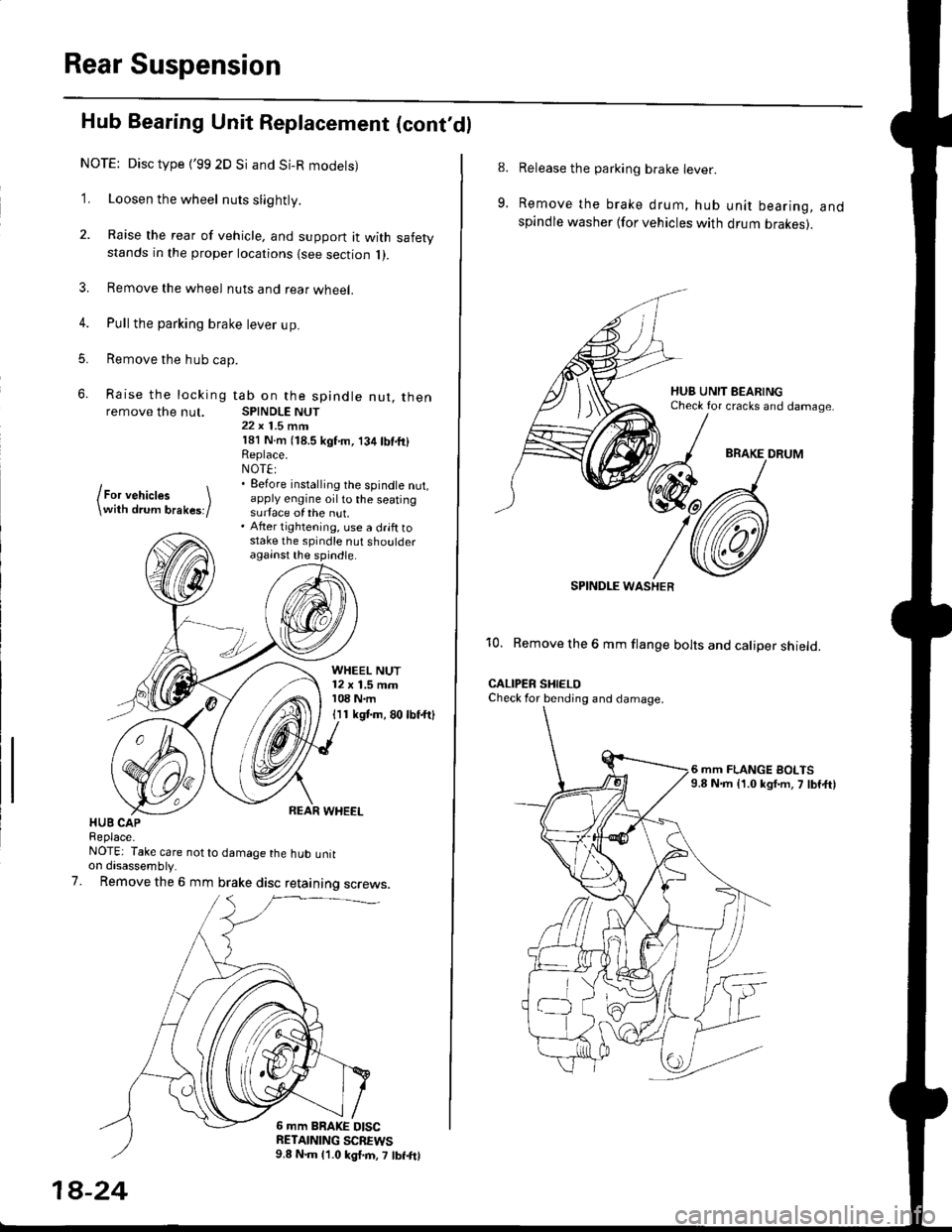
Rear Suspension
Hub Bearing Unit Replacement (cont'dl
NOTE: Disc type {'99 2D Si and Si-R modets)
1. Loosen the wheel nuts slightly.
2. Raise the rear of vehicle, and support it with safetystands in the proper locations {see section 1).
3. Remove the wheel nuts and rear wheel.
4. Pull the parking brake lever up.
5. Remove the hub cap.
6. Raise the locking tab on the spindle nut, thenremove the nut. SPINDLE NUT22 x 1.5 mrn181 N.m (18.5 kgf'm, 134lbf.fi)Replace.NOT€:. Eefore installing the spindle nut,apply engine oil to the seatingsurface of the nut.. After tightening, use a drift tostake the spindle nut shoulderagainst the spindle.
lFor vehictes \\with drum brakes;/
WHEEL NUT12 x 1.5 mm108 N.m
I I 1 kgt m, 80 lbf.ftl
HUB CAPReplace-NOTE: Take care not to damage the hub untton disassembly.
Remove the 6 mm brake disc retaining screws.7.
6 mm BRAKE DISCRETAINING SCBEWS9.8 N.m 11.0 kgl.m, 7 lbf.frl
1A-24
8.
9.
Release the parking brake lever.
Remove the brake drum, hub unit bearing, andspindle washer lfor vehicles with drum brakes).
BRAKE DRUM
SPINDI-E WASHER
10. Remove the 6 mm flange bolts and caliper shield.
CALIPER SHIELOCheck for bending and damage.
6 mm FLANGE BOLTS9.8 N.m {1.0 kgf.m, 7 lbf,ft)
Page 1159 of 2189
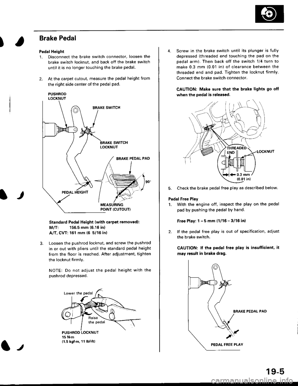
)
Brake Pedal
Pedal Height
1. Disconnect the brake switch connector, loosen the
brake switch locknut, and back off the brake switch
until it is no longer touching the brake pedal,
2. At the carpet cutout, measure the pedal height from
the right side center of the pedal pad.
PUSHRODLOCKNUT
Standard Pedal Height (with carpet removed):
M/T: 156.5 mm 16.16 inl
A/T, CVT: 161 mm (5 5/16 in)
3. Loosen the pushrod locknut, and screw the pushrod
in or out with pliers until the standard pedal height
from the floor is reached. After adjustment, tighten
the locknut firmly.
NOTE: Do not adiust the pedal height with the
Dushrod depressed.
It
PUSHROO LOCKNUT15 N.m(1.5 kgf.m. 11 lbI.ft)
POINT ICUTOUTI
4. Screw in the brake switch until its plunger is fully
depressed (threaded end touching the pad on the
pedal arm). Then back off the switch 1/4 turn to
make 0.3 mm (0.01 in) of clearance between the
threaded end and pad. Tighten the locknut firmly.
Connect the brake switch connector.
CAUTION: Make sure that the brake lights go off
when the pedal is released.
LOCKNUT
5. Check the brake pedal free play as described below.
Pedal Free Plsy
1. With the engine off, inspect the play on the pedal
pad by pushing the pedal by hand.
Free Play: 1 - 5 mm (1/16 - 3/16 inl
2. lf the pedal free play is out of specitication, adjust
the brake switch.
CAUTION: lf the pedal free play is insufficient, it
may result in brake drag.
BRAKE PEDAL PAO
)
19-5
*0.3 mm(0.01 in)