Circuit diagram HONDA CIVIC 2000 6.G User Guide
[x] Cancel search | Manufacturer: HONDA, Model Year: 2000, Model line: CIVIC, Model: HONDA CIVIC 2000 6.GPages: 2189, PDF Size: 69.39 MB
Page 1378 of 2189
![HONDA CIVIC 2000 6.G User Guide Circuit Diagram
96 - 98 Models
LINDEF NoOD FUSETFELAY 30x
WNTTBLK +WFT
8L|(YEi
LIGHT
Y
I
No1l lS0Al Ni42 (40A)
S;rt | | lieti{,**i-t L-:} [:] | h
crca(.-A-o \1 \-r. \-r-1 \\
!9[1 ? _?__?? _t__? HONDA CIVIC 2000 6.G User Guide Circuit Diagram
96 - 98 Models
LINDEF NoOD FUSETFELAY 30x
WNTTBLK +WFT
8L|(YEi
LIGHT
Y
I
No1l lS0Al Ni42 (40A)
S;rt | | lieti{,**i-t L-:} [:] | h
crca(.-A-o \1 \-r. \-r-1 \\
!9[1 ? _?__?? _t__?](/img/13/6068/w960_6068-1377.png)
Circuit Diagram
'96 - 98 Models
LINDEF NoOD FUSETFELAY 30x
WNTTBLK +WFT
8L|(YEi
LIGHT
Y
I
No1l lS0Al Ni42 (40A)
S;rt' | | lieti{,**i'-t L-:} [:] | h
crca(.-A-o \1 \-r. \-r-1 \'\
!9[1' ? _?__?'? _t__?__t
21-4
Page 1410 of 2189
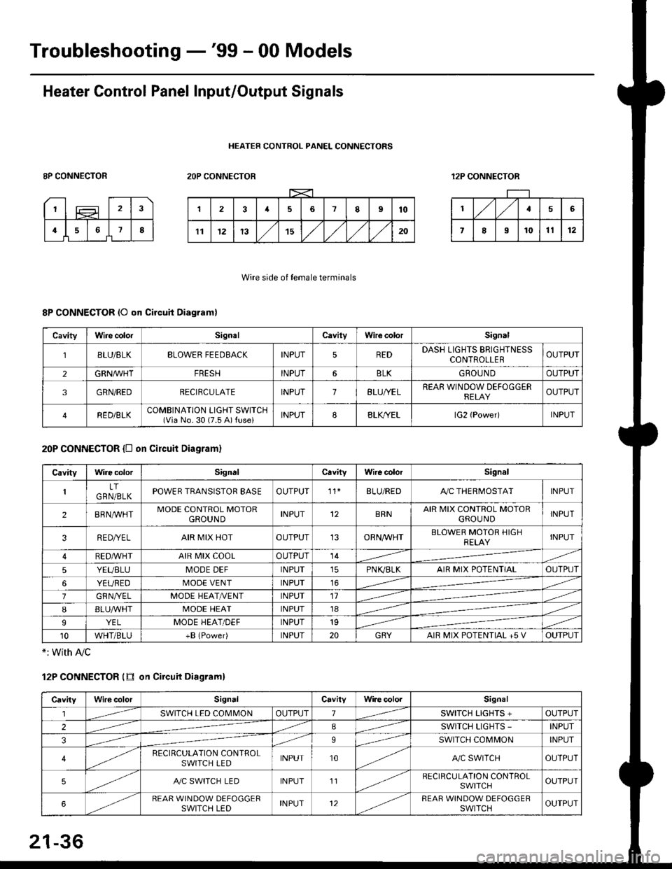
Troubleshooting -'99 - 00 Models
Heater Control Panel Input/Output Signals
HEATER CONTROL PANEL CONNECTORS
8P CONNECTOR2OP CONNECTOR12P CONNECTOR
Wire side of female terminals
8P CONNECTOR (O qn Circuit Diagram)
20P CONNECTOR {D on circuit Diagram}
*: with Ay'c
12P CONNECTOR (tr on Circuit Diagraml
CavityWire colorSignalCavilyWhe colorSignal
BLU/8LKBLOWER FEEDBACKINPUT5REDDASH LIGHTS BRIGHTNESSCONTROLLEROUTPUT
2GRN/lVHTFRESHINPUT6BLKGBOU N DOUTPUT
3GRN/REDRECIRCULATEINPUT7BLU/YELREAR WINDOW DEFOGGERRELAYOUTPUT
4RED/BLKCOMBINATION LIGHT SWITCH(Via No. 30 (7.5 A) fuse)INPUT88LfiELlG2 {Power)INPUT
CavityWire colorSignalCavityWire colorSignal
LTGRN/BLKPOWER TRANSISTOR EASEOUTPUT't1BLU/REDAy'C THERMOSTATINPUT
2BRNMHTMODE CONTROL MOTORGROUNDINPUT12BRNAIR MIX CONTROL MOTORGROU NDINPUT
3RE D/YELAIR MIX HOTOUTPUT13ORNAA/HTBLOWER MOTOR HIGHRELAYINPUT
RED,ryvHIAIR MIX COOLOUTPUT14
5YEUBLUMODE DEFINPUTPN K,/BLKAIR MIX POTENTIALOUTPUT
6YEUREDMODE VENTINPUT16
7GRNI/ELMODE HEAT/r'ENTINPUT11
IBLUAVHTMODE HEATINPUT18
9YELMODE HEAT/DEFINPUT19
10WHT/BLU+B (Power)INPUT20GRYAIR MIX POTENTIAL +5 VOUTPUT
CavityWilecolorSignalCavityWi.e cololSignal
lSWITCH LED COMMONOUTPUT1SWITCH LIGHTS +OUTPUT
2ISWITCH LIGHTS -INPUT
39SWITCH COMMONINPUT
4RECIRCULATION CONTROLSWITCH LEDINPUT10A,/C SWITCHOUTPUT
5A./C SWITCH LEDINPUT11RECIRCULATION CONTROLSWITCHOUTPUT
6REAR WINDOW DEFOGGERSWITCH LEDINPUT12REAR WINDOW DEFOGGEBSWITCHOUTPUT
21-36
Page 1425 of 2189
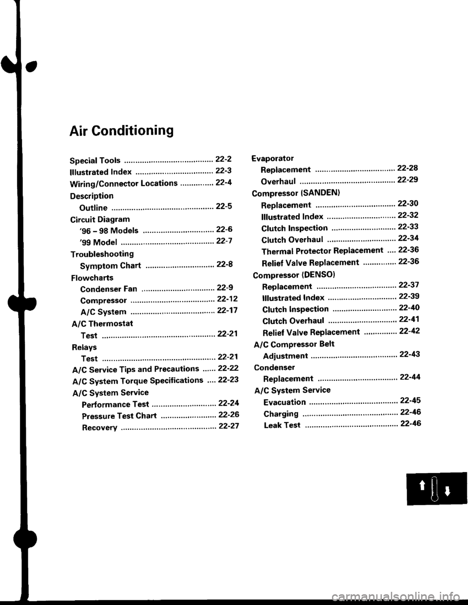
Air Conditioning
Speciaf Tools ......'.....' 22-2
f f f ustrated f ndex ......................... ".......' 22-3
Wiring/Connector Locations'.........'.... 22'4
Description
Outfine ............ .......22-s
Circuit Diagram
'96 - 98 Models ......"..........".......'.... 22-6
'99 Modef """""""' 22-7
Troubleshooting
Symptom Chart ".'......""................. 22-8
Flowcharts
Condenser Fan .........".................,..'. 22-9
Compressor .....""" 22-12
A/C System .........'.22'17
A/C Thermostat
Test ........'.......' """'22'21
Relays
Test ....."'......... ..""'22-21
A/C Service Tips and Precautions ......22-22
A/C System Torque Specifications '...22-23
A/C System Service
Performance Test ... '."......... ".... ....'..22-24
Pressure Test Chart .................. .... "' 22-26
Recovery ...".........," 22-27
Evaporator
Replacement .....",' 22'24
Overhauf .....-.....""' 22'29
Compressor {SANDEN}
Repf acement ......'.' 22-30
fffustrated fndex ......"..................'.... 22'32
Cf utch Inspection ......... "............ ...... 22-33
Clutch Overhau I ........................ ....... 22-34
Thermal Protector Replacement .... 22-36
Relief Valve Replacement ......'..."". 22-36
Compressor (DENSO)
Repfacement ..""',' 22-37
lf lustrated Index ............................... 22-39
Clutch lnspection ............."'...... "'.... 22-40
Cf utch Overhaul .....................'......... 22-41
Ref ief Valve Replacement'..'......"'.. 22-42
A/C Compressor Belt
Adiustment ............22'43
Condenser
Repfacement .......,,22'44
A/C System Service
Evacuation ...,,,.......22-45
Charging '..........--'..22'46
Leak rest """""""'22-46
Page 1430 of 2189
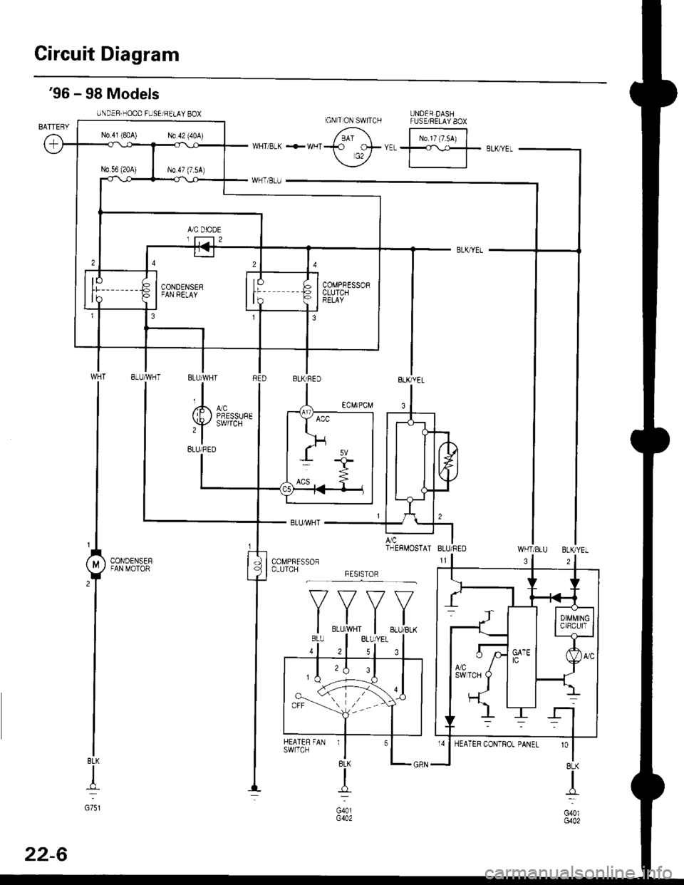
Circuit Diagram
UNDER DASHFUSE/RELAY 8OX
N0.17 (7.54)
'96 - 98 Models
UNDER.HOOD FUSEi BELAY BOX
WHT/SLU BLKYEL
BLK
+
G751
3
'o
I8LK
I
G40lG402
GNITON SWITCH
N0.41 (8rA) N0.42 (40A)
COMPBESSORCLUTCHBELAY
BLUMHT
,l
(E) i,T'
BLUi BED
A/c ITHERMOSTAI BLU/REO
CONDENSEFFAN MOTOR
*F,.X,
FAN rl
BLK
{
G401G402
HEATERswrlcH
32
22-6
Page 1471 of 2189

l'f .
Electrical
Special Toofs .,....................,23-2
Troubleshooting
Tips and Precautions ..............,.................... . 23-3
Five-step Troubleshooting .............. ......... . . 23-5
wire color codes ..........,23-5
Schematic Symbols ........,................... . . .. .... 23-6
Relay and Control Unit Locations
Engine Compartment ...,..................... ... .. . 23'7
Dashboard ......................23-8
Dashboard/Door ......... 23-12*Airbags ................. ....... Section 24
Air Conditioning ......... Section 21
Aftelnator ..........."""" """ 23-112
Anti-lock Brake System {ABS) Section 19*A/T Gear Position Indicator .....................,. .... ... 23-149
Automatic Transmission Svstem .... . ....... Section 14
Batterv ......... . . . ... ...... .......23-91
Blower controls .. . ... Section 2l
Charging System ....'...........23'112
Connector ldentilication and Wire Harness
Routing .................. ......23'13
Cruise Control ............,........23-240
Dash Lights Brightness Controller ............. ....... 23-180
Fan controfs "" 23'126
Fuel PumD ........ . ........ section 11
Fuses/Refay ...............,..,,.. 23'62
PGM-FI Control System ......................,....... Section 1 1
*Gauges
Circuit Diagram ....,.,.......23-131
Fuef Gauge ...........'.'.......23-142
Gauge/lndicator .. . .. 23-129
Ground Distribution .. . 23-75
Heatei controls .. . ..... Section 21*Horn................. ...............23-196
*tgnition Switch ....................23-89
lgnition System .......,.... 23-102
*lntegrated Control Unit ....................................... 23-156
fnterlock System ,........ . . , ,23-144
Lighting System . . . .. ......... 23-161
Lights, Exterior
Back-up Lights ..'............23'171
Brake Lights .................. 23'174
Daytime Bunning Lights (Canadal ............... 23'166
Front Parking Lights ......,................ .'. .......... 23-167
Front Turn Signal Lights .......... . . ............ ..,.23-167
Headtights ....".'....-... ..... 23'167
High Mount Brake Light ...................... ... .23'179
License Plate Lights ...... 23'176
Taitfights ................ .......23'171
lnterior Lights ..-.......,, . 23-142
Moonroof ..,.................,........ 23-235
Power Distribution ....... . . .23-61
Power Door Locks .......,,,. .23'251
Power Mirrors ,..............,.,...23'206
Power Relays ....... . ...... . . .. 23-86
Power Windows ............,,....23-220
Rear Window Defogger .......................... . . ... . . 23-2OO
Spark Plugs . ..... . ........ .....23-111
Slarting System ................23-93*stereo Sound Svstem ,................. ..... ... . ... ,.,.,,23'147'Supplemental Restraint System (SRS) ... . Section 24
Turn Signal/Hazard Flasher System .......'.'....-... 23-173
*Undel-dash Fuse/Relay Box ............,.................. 23-85
vehicfe soeed sensor (VSSI """" ""' 23-140+Wipers/Washers .........,.,.,...23-214
NOTE: Unless otherwise specified, references to auto-
matic transmission (Mf) in this section include the CVT.
Page 1573 of 2189
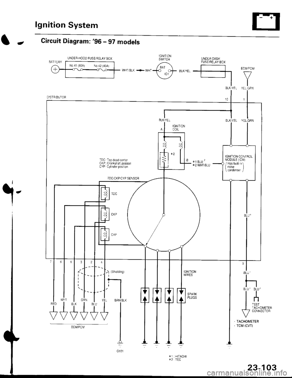
lgnition System
-Circuit Diagram: '96 - 97 models
.i-
8LU
I
nBLU BLU I
tl
lnI TESTI TACHOMETEF\-7 CONNECTOR
TACHOMETERTCM (CW)
J-) {sh,eldinsr't I
tfYEL BBN/BLK
+l
I:
G101
$t+++
UNDER HOOD FUSE/ RELAY 8OX
BLh TEL YEL GBN
BLKlYEL
IAl
BLK/YEL YELIGFN
IGN]TIONCOL
TDCrTop dead cenlerCKP: Crankshall postionCYP Cylnder poslon
TDC]CKP]CYP SENSoR
" *]BLU'*2 WHI BLU
IGNITION CONIROLMODULE (CM)
/ Has b'r ll n\I iorse I
rUSE FE-AV BO}
*u r-. .-*---{<9ot # u,,."r. | |
\j/ El v
tl
23-103
Page 1574 of 2189
![HONDA CIVIC 2000 6.G User Guide lgnition System
Circuit Diagram :98-00 models
UNDER HOOD FUSUFELAY BOXxE;;;;-;;;;l /; l-*;- Ecw.cM
ffiwFnBLK<-wHr\9-
Y
tlBTKTYEL YEUGRN
IGN]TIONswtTcHUNDER,DASHFUSE/BELAY BOX
YEt
J
BLK
J
FED
+
*1 HONDA CIVIC 2000 6.G User Guide lgnition System
Circuit Diagram :98-00 models
UNDER HOOD FUSUFELAY BOXxE;;;;-;;;;l /; l-*;- Ecw.cM
ffiwFnBLK<-wHr\9-
Y
tlBTKTYEL YEUGRN
IGN]TIONswtTcHUNDER,DASHFUSE/BELAY BOX
YEt
J
BLK
J
FED
+
*1](/img/13/6068/w960_6068-1573.png)
lgnition System
Circuit Diagram :'98-00 models
UNDER HOOD FUSUFELAY BOX'x'E;;;;-;;;;l /; l-*;- Ecw.cM
ffiwFnBLK<-wHr\9-
Y
tlBTKTYEL YEUGRN
IGN]TIONswtTcHUNDER,DASHFUSE/BELAY BOX
YEt
J
BLK
J
FED
+
*1 :H TACHI*2 :TEC
9 *IBLU'
23-104
Page 1583 of 2189
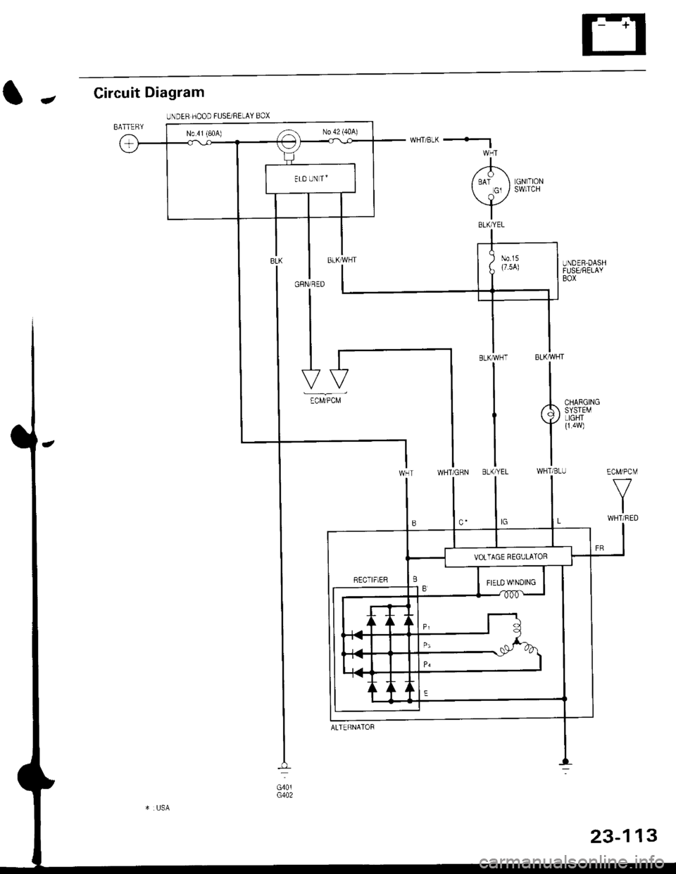
Circuit Diagram
IJNDER HOOD FUSEi RELAY BOX
-
BATTERY
LGNlTIONSWITCH
I
,'-F\I BAT I Gl /
\l_/
I
GRN/RED
I
N0.41 (80A) ,-a No 42 (40A)
ECM/PCM
f7
IWHT/RED
CHARGINGSYSTEMLIGHTI
TWHTi BLU
1323-1
ALTERNATOF
Page 1597 of 2189
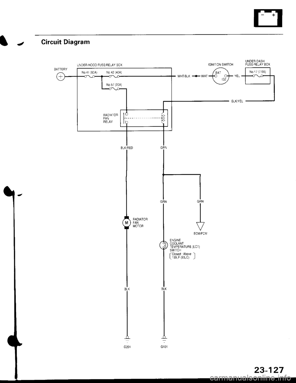
IJCircuit Diagram
UNDER DASHIGNIT ON SWITCH FUSEIRELAY 8OX
6 |-;;;;lii "ir"'t*Tl-l
BLK yEL -J
GRN
III
I
\.7VECM/PCM
ENG NECOOLANTlEMPERATURE (ECT)SWTCHfclosed : Above 'l
L r99"F (93"C) _l
BLKTRED
I
I
1,,*"_
T-'
IBtK
I
I
G201
UNDER.HOOD FUSElRELAY BOX
No 41 (8041 No 42 (40A)
Page 1602 of 2189
![HONDA CIVIC 2000 6.G User Guide Gauge Assembly
(Wnh lachomolgr)
I cNfldt--]I CONTRoL II MODULE
I 0cM) :
tvl
i.ll
|
-i;,
i
TURN SIGNAUHAZAROWARNINGswtTcH
Circuit Diagram {contd)
Fh"lurous @)- BLrcwHT + BLKryEL
fiSfvrous 16r.- veL HONDA CIVIC 2000 6.G User Guide Gauge Assembly
(Wnh lachomolgr)
I cNfldt--]I CONTRoL II MODULE
I 0cM) :
tvl
i.ll
|
-i;,
i
TURN SIGNAUHAZAROWARNINGswtTcH
Circuit Diagram {contd)
Fh"lurous @)- BLrcwHT + BLKryEL
fiSfvrous 16r.- veL](/img/13/6068/w960_6068-1601.png)
Gauge Assembly
(Wnh lachomolgr)
I cNfldt--]I CONTRoL II MODULE
I 0cM) :
tvl
i.ll
|
-i;,
i
TURN SIGNAUHAZAROWARNINGswtTcH
Circuit Diagram {cont'd)
Fh"lurous @)- BLrcwHT + BLKryEL
fi'Sfvrous 16r.- veLPAGE
RIGHT
V
IGR&ryE
LEFT
V
I
No.s (104)FUSE
V
IBEO/GRN
lru
8LU4RE0
ABSCONTROLUNIT
-rl
eLui'rvrr
G401G402G401G442
23-132