Diagram HONDA CIVIC 2000 6.G User Guide
[x] Cancel search | Manufacturer: HONDA, Model Year: 2000, Model line: CIVIC, Model: HONDA CIVIC 2000 6.GPages: 2189, PDF Size: 69.39 MB
Page 907 of 2189
![HONDA CIVIC 2000 6.G User Guide PCM Circuit Diagram (A/T Control System: gg - 00 Models)
UADEF DSIFUSSFEUY 8OXr{o.2s (7 5A)
tGNtTtc{lSWTCHUNDER.OASNFUSF]NEUY 8OI
iPrE: T ro sv
INlD
,:--
^1 GETB POSITIoi{
14-230 HONDA CIVIC 2000 6.G User Guide PCM Circuit Diagram (A/T Control System: gg - 00 Models)
UADEF DSIFUSSFEUY 8OXr{o.2s (7 5A)
tGNtTtc{lSWTCHUNDER.OASNFUSF]NEUY 8OI
iPrE: T ro sv
INlD
,:--
^1 GETB POSITIoi{
14-230](/img/13/6068/w960_6068-906.png)
PCM Circuit Diagram (A/T Control System: 'gg - 00 Models)
UADEF D'SIFUSSFEUY 8OXr{o.2s (7 5A)
tGNtTtc{lSWTCHUNDER.OASNFUSF]NEUY 8OI
iPrE: T ro sv
INlD
,:--
^1 GETB POSITIoi{
14-230
Page 1057 of 2189
l.
t
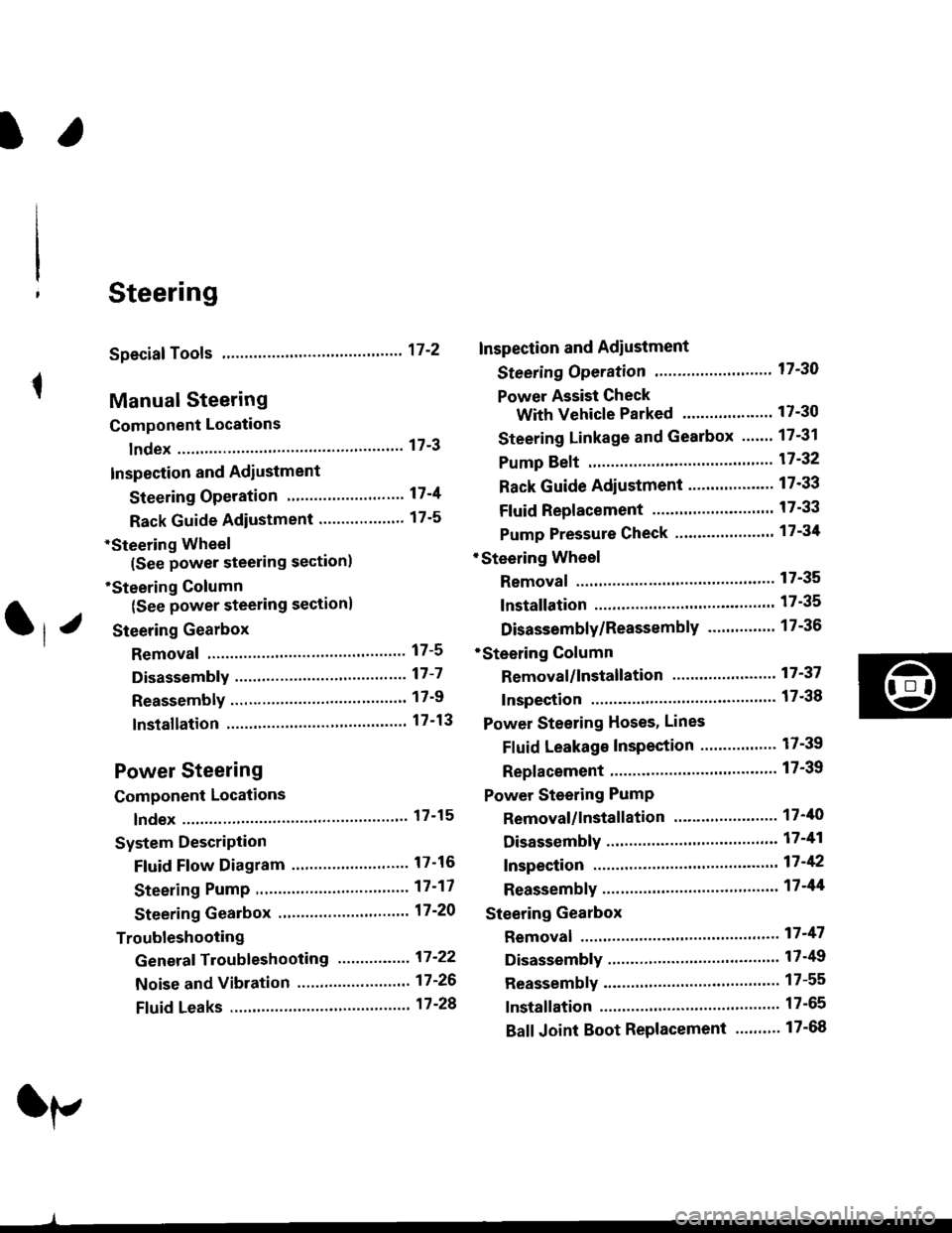
Steering
Speciaf Tools ....."'.....17-2
Manual Steering
Component Locations
lndex ................ ....... 17-3
Inspection and Adiustment
Steering Operation "'......"............... 17-4
Rack Guide Adiustment ................... 17-5
*Steering Wheel
(See power steering section)
*Steering Column
(See power steering sectionl
Steering Gearbox
Removal ................. 17-5
Disassembly ......."" 17-7
ReassemblY ..'......... 17-9
lnstallation ............. 17-13
Power Steering
Component Locations
lndex "......."..... """' 17-15
System DescriPtion
Fluid Flow Diagram .........""............. 17'16
Steering Pump ............'... "........"'...-- 17 -17
Steering Gearbox .".................'...'.'.' 17-20
Troubleshooting
Generaf Troubleshooting ..........--.... 17'22
Noise and Vibration ......................... 17 -26
Ffuid Leaks .............17-28
Inspection and Adiustment
Steering Operation'......."'........'...... 1 7-30
Power Assist Check
With Vehicle Parked .."................ 17-30
Steering Linkage and Gearbox ....." 17-31
Pump Beft ...--.""".. 17-32
Rack Guide Adiustment .'.......'.......'. 17'33
Fluid Replacement .....'.."................. 17-33
Pump Pressure Check .............'....-. " 17 -34
'Steering Wheel
Removal .."'........'... 17-35
lnstallation ............. 17-35
Disassembly/Reassembly ......'.....'.' 17-36
*Steering Column
Removal/lnstallation ....'........... ---.... 17'37
lnspection .............. 17'38
Power Steering Hoses, Lines
Fluid Leakage Inspeetion ............'.... 17-39
Replacement ......".. 17-39
Power Steering PumP
Removal/lnstallation .'.'..'..'............. 17-40
Disassembly ".........17-41
fnspection .......---'." 17'42
Reassembly ..'.........17-44
Steering Gearbox
Removal ....'........."' 17'47
DisassemblY ..........' 17-49
Reassembly '........... 17-55
lnstallation ............. 17-65
Ball Joint Boot Replacement .......'.. 17-68
Ir/
lp
Page 1072 of 2189
System Description
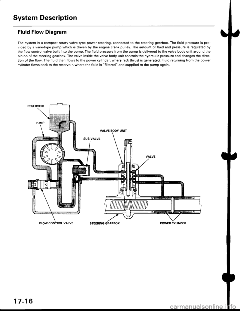
Fluid Flow Diagram
The system is a compact rotary-valve-type power steering, connected to the steering gearbox. The fluid pressure is pro-
vided by a vane-type pump which is driven by the engine crank pulley. The amount of fluid and pressure is regulated by
the flow control valve built into the pump. The fluid pressure from the pump is delivered to the valve body unit around the
pinion of the steering gearbox. The valve inside the valve body unit controls the hydraulic pressure and changes the direc-
tion of the flow. The fluid then flows to the power cylinder. where rack thrust is generated. Fluid returning from the power
cylinder flows back to the reservoir, where the fluid is "filtered" and supplied to the pump again.
RESERVOIR
VALVE BOOY UNIT
SUB.VALVE
FLOW CONTROL VALVESTEERING GEARBOX
17-16
Page 1196 of 2189
L-
t
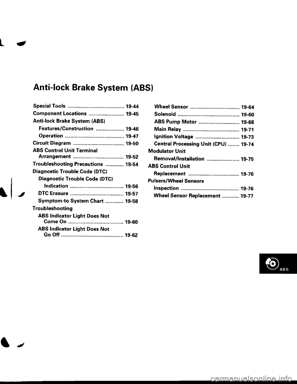
Anti-lock Brake System (ABSI
Special Tools ............. 19-44
Component Locations ......................... 19-45
Anti-lock Brake System (ABS)
Features/Construction ..................., 19-46
Operation ............... 19-47
Circuit Diagram ......... 19-50
ABS Control Unit Terminal
Arrangement ......... 19-52
Troubleshooting Precautions ............. 19-54
Diagnostic Trouble Code (DTCI
Diagnostic Trouble Gode (DTCI
Indication ........... 19-56
DTC Erasure ........... 19-57
Symptom-to System Chart ............. 19-58
Troubleshooting
ABS Indicator Light Does Not
Come On ............ 19-60
ABS Indicator Light Does Not
Go Off ............................................ 19-62
Wheel Sensor ........ 19-64
Solenoid ................. 19-60
ABS Pump Motor ............................. 19-68
Main Relay ............. 19-71
lgnition Voltage .... 19-73
Central Processing Unit {CPU} ........ 19-74
Modulator Unit
Removal/lnstallation ....................... 19-75
ABS Control Unit
Replacement ......... 19-76
Pulsers/Wheel Sensors
Inspection .............. 19-76
Wheel Sensor Replacement ............ 19-77
t/
Page 1203 of 2189
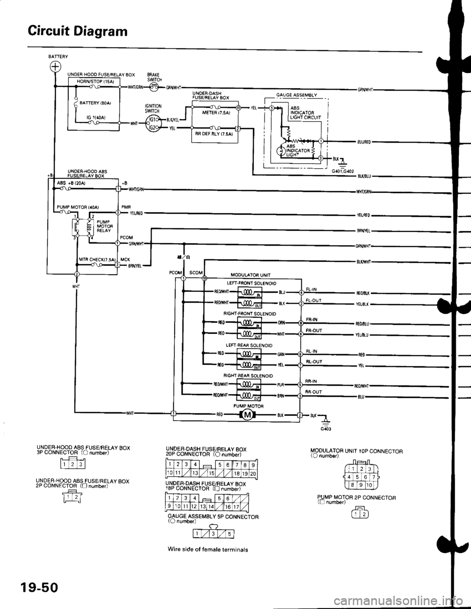
Gircuit Diagram
MOOULATOR UNIT IOP CONNECTOR
zrJrF!_lll 2 3ll
14TiEltl
c@4
PIMP MOTOR 2P CONNECTOR(Ll number)fFlGTN
UNDER.HOOO A8S FUSE,/FELAY BOX3P CONNECTOR (O number)
| 2 3l
UNDER.HOOD AAS FUSE/RELAY BOX2P CONNECTOR (! number)
| -l
GAUGE ASSEMELY 5P CONNECTOR
---t--t1 t/ 13 )/l5l
Wire side ot temale terminals
- E8l{'Ytr
AA DEF BLY I7.5AI
_@f_u,
n4@f-n,
LEFT.FSONT SOLENOIO
UNDER-OASH FUSSRELAY 8OXZoP CONNECTOR (O numbe,
235678It0tlt3/ i15 /t820
UNDER.OASH FUSE,/RELAY BOX18P CONNECTOR (E numb€r)
23569ll213)t4 /1617
19-50
Page 1375 of 2189
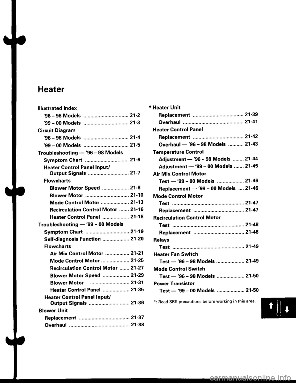
Heater
lllustrated Index
'96 - 98 Models ................................ 21'2
'99 - 00 Models ................................ 21'3
Circuit Diagram
'96 - 98 Models .....21-4
'99 - 00 Models ................................ 21-5
Troubleshooting - '96 - 98 Models
Symptom Chart ............................... 21-6
Heater Control Panel Input/
Output Signals ..............,.............. 21-7
Flowcharts
Blower Motor Speed ................... 21-8
Bf ower Motor ,...21'10
Mode Control Motor ............... ,.'.' 21-13
Recirculation control Motor ....... 21-16
Heater Control Panel ................ ... 21 -14
Troubleshooting - '99 - 00 Models
Symptom Chart ............................... 21-19
Seff-diagnosis Function ............,,,.... 21-20
Flowcharts
Air Mix Control Motor ......,.......... 21-21
Mode Control Motor ............... ..... 21 -25
Recirculation Control Motor ....... 21-27
Bf ower Motor Speed .............. .....21'29
Bf ower Motor ....21-31
Heater Control Panel ................,.. 21-35
Heater Control Panel Input/
Output Signals ............................. 21-36
Blower Unit
Repf acement .........21-37
Overhaul ................ 21-38
* Heater Unit
Replacement ....'....21-39
overhaul """" """' 21-4'l
Heater Control Panel
Repfacement .........21'42
Overhaul -'96 - 98 Models ........... 21-43
Temperature Control
Adjustment - '96 - 98 Models """" 21-44
Adiustment - '99 - 00 Models .......21-45
Air Mix Control Motor
Test - '99 - 00 Models ...........' .......21'46
Replacement - '99 - 00 Models ....21'46
Mode Control Motol
Test ................, .,...'.21'47
Replacement '.'."...21-47
Recirculation Control Motor
Test ................. .......21-48
Repf acement ......." 21-48
Relays
Test ................. .......2'l-49
Heater Fan Switch
Test - '96 - 98 Models ............. .......21-49
Mode Control Switch
Test -'96 - 98 Models ..........."....... 21-50
Power Transistor
Test - '99 - 00 Models ....'........ ....".21-50
*: Read SRS Drecautions before working in this area.
Page 1378 of 2189
![HONDA CIVIC 2000 6.G User Guide Circuit Diagram
96 - 98 Models
LINDEF NoOD FUSETFELAY 30x
WNTTBLK +WFT
8L|(YEi
LIGHT
Y
I
No1l lS0Al Ni42 (40A)
S;rt | | lieti{,**i-t L-:} [:] | h
crca(.-A-o \1 \-r. \-r-1 \\
!9[1 ? _?__?? _t__? HONDA CIVIC 2000 6.G User Guide Circuit Diagram
96 - 98 Models
LINDEF NoOD FUSETFELAY 30x
WNTTBLK +WFT
8L|(YEi
LIGHT
Y
I
No1l lS0Al Ni42 (40A)
S;rt | | lieti{,**i-t L-:} [:] | h
crca(.-A-o \1 \-r. \-r-1 \\
!9[1 ? _?__?? _t__?](/img/13/6068/w960_6068-1377.png)
Circuit Diagram
'96 - 98 Models
LINDEF NoOD FUSETFELAY 30x
WNTTBLK +WFT
8L|(YEi
LIGHT
Y
I
No1l lS0Al Ni42 (40A)
S;rt' | | lieti{,**i'-t L-:} [:] | h
crca(.-A-o \1 \-r. \-r-1 \'\
!9[1' ? _?__?'? _t__?__t
21-4
Page 1410 of 2189
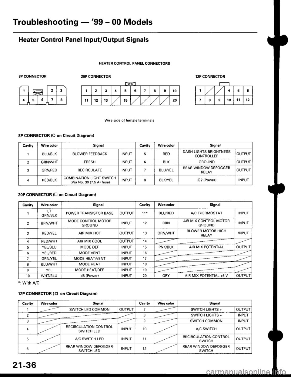
Troubleshooting -'99 - 00 Models
Heater Control Panel Input/Output Signals
HEATER CONTROL PANEL CONNECTORS
8P CONNECTOR2OP CONNECTOR12P CONNECTOR
Wire side of female terminals
8P CONNECTOR (O qn Circuit Diagram)
20P CONNECTOR {D on circuit Diagram}
*: with Ay'c
12P CONNECTOR (tr on Circuit Diagraml
CavityWire colorSignalCavilyWhe colorSignal
BLU/8LKBLOWER FEEDBACKINPUT5REDDASH LIGHTS BRIGHTNESSCONTROLLEROUTPUT
2GRN/lVHTFRESHINPUT6BLKGBOU N DOUTPUT
3GRN/REDRECIRCULATEINPUT7BLU/YELREAR WINDOW DEFOGGERRELAYOUTPUT
4RED/BLKCOMBINATION LIGHT SWITCH(Via No. 30 (7.5 A) fuse)INPUT88LfiELlG2 {Power)INPUT
CavityWire colorSignalCavityWire colorSignal
LTGRN/BLKPOWER TRANSISTOR EASEOUTPUT't1BLU/REDAy'C THERMOSTATINPUT
2BRNMHTMODE CONTROL MOTORGROUNDINPUT12BRNAIR MIX CONTROL MOTORGROU NDINPUT
3RE D/YELAIR MIX HOTOUTPUT13ORNAA/HTBLOWER MOTOR HIGHRELAYINPUT
RED,ryvHIAIR MIX COOLOUTPUT14
5YEUBLUMODE DEFINPUTPN K,/BLKAIR MIX POTENTIALOUTPUT
6YEUREDMODE VENTINPUT16
7GRNI/ELMODE HEAT/r'ENTINPUT11
IBLUAVHTMODE HEATINPUT18
9YELMODE HEAT/DEFINPUT19
10WHT/BLU+B (Power)INPUT20GRYAIR MIX POTENTIAL +5 VOUTPUT
CavityWilecolorSignalCavityWi.e cololSignal
lSWITCH LED COMMONOUTPUT1SWITCH LIGHTS +OUTPUT
2ISWITCH LIGHTS -INPUT
39SWITCH COMMONINPUT
4RECIRCULATION CONTROLSWITCH LEDINPUT10A,/C SWITCHOUTPUT
5A./C SWITCH LEDINPUT11RECIRCULATION CONTROLSWITCHOUTPUT
6REAR WINDOW DEFOGGERSWITCH LEDINPUT12REAR WINDOW DEFOGGEBSWITCHOUTPUT
21-36
Page 1425 of 2189
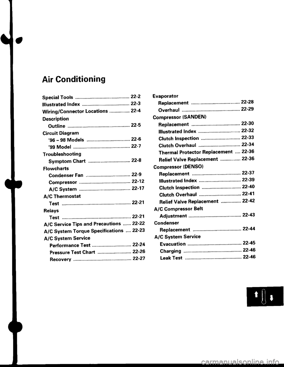
Air Conditioning
Speciaf Tools ......'.....' 22-2
f f f ustrated f ndex ......................... ".......' 22-3
Wiring/Connector Locations'.........'.... 22'4
Description
Outfine ............ .......22-s
Circuit Diagram
'96 - 98 Models ......"..........".......'.... 22-6
'99 Modef """""""' 22-7
Troubleshooting
Symptom Chart ".'......""................. 22-8
Flowcharts
Condenser Fan .........".................,..'. 22-9
Compressor .....""" 22-12
A/C System .........'.22'17
A/C Thermostat
Test ........'.......' """'22'21
Relays
Test ....."'......... ..""'22-21
A/C Service Tips and Precautions ......22-22
A/C System Torque Specifications '...22-23
A/C System Service
Performance Test ... '."......... ".... ....'..22-24
Pressure Test Chart .................. .... "' 22-26
Recovery ...".........," 22-27
Evaporator
Replacement .....",' 22'24
Overhauf .....-.....""' 22'29
Compressor {SANDEN}
Repf acement ......'.' 22-30
fffustrated fndex ......"..................'.... 22'32
Cf utch Inspection ......... "............ ...... 22-33
Clutch Overhau I ........................ ....... 22-34
Thermal Protector Replacement .... 22-36
Relief Valve Replacement ......'..."". 22-36
Compressor (DENSO)
Repfacement ..""',' 22-37
lf lustrated Index ............................... 22-39
Clutch lnspection ............."'...... "'.... 22-40
Cf utch Overhaul .....................'......... 22-41
Ref ief Valve Replacement'..'......"'.. 22-42
A/C Compressor Belt
Adiustment ............22'43
Condenser
Repfacement .......,,22'44
A/C System Service
Evacuation ...,,,.......22-45
Charging '..........--'..22'46
Leak rest """""""'22-46
Page 1430 of 2189
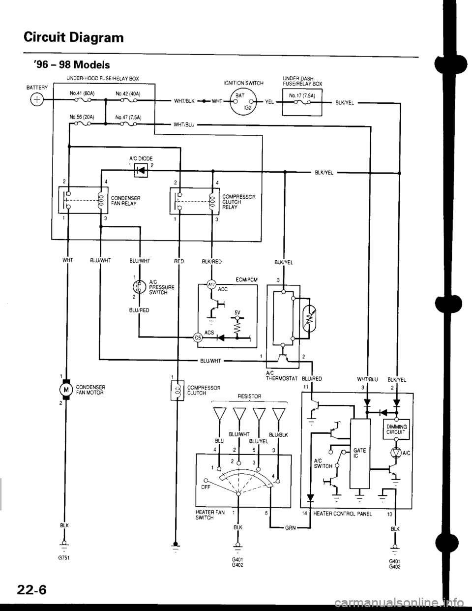
Circuit Diagram
UNDER DASHFUSE/RELAY 8OX
N0.17 (7.54)
'96 - 98 Models
UNDER.HOOD FUSEi BELAY BOX
WHT/SLU BLKYEL
BLK
+
G751
3
'o
I8LK
I
G40lG402
GNITON SWITCH
N0.41 (8rA) N0.42 (40A)
COMPBESSORCLUTCHBELAY
BLUMHT
,l
(E) i,T'
BLUi BED
A/c ITHERMOSTAI BLU/REO
CONDENSEFFAN MOTOR
*F,.X,
FAN rl
BLK
{
G401G402
HEATERswrlcH
32
22-6