light HONDA CIVIC 2000 6.G User Guide
[x] Cancel search | Manufacturer: HONDA, Model Year: 2000, Model line: CIVIC, Model: HONDA CIVIC 2000 6.GPages: 2189, PDF Size: 69.39 MB
Page 187 of 2189
Valves, Valve Springs and Valve Seals
Removal
NOTE: ldentify valves and valve springs as they are
removed so that each item can be reinstalled in its origi-
nal Dosition.
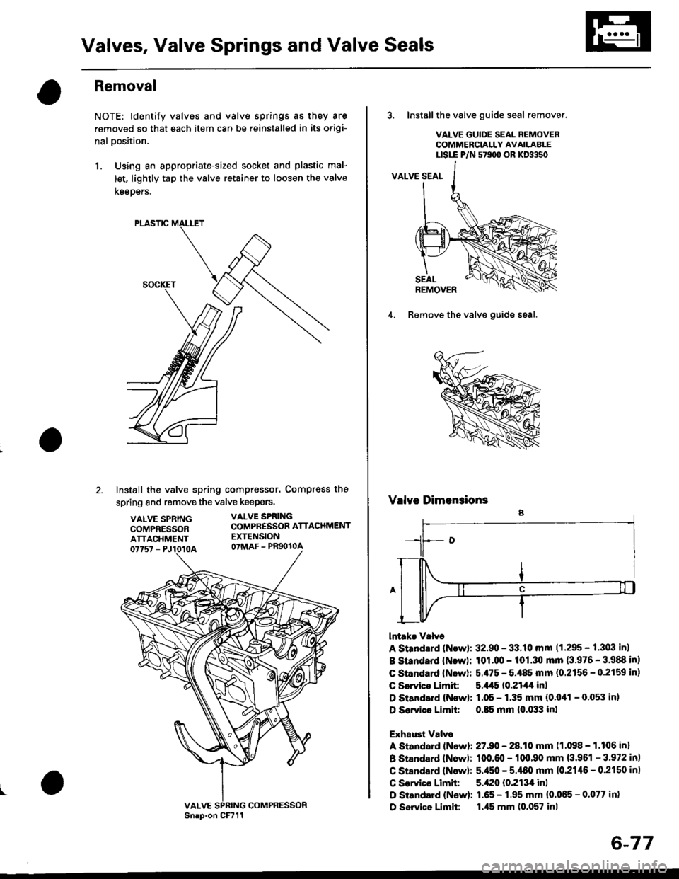
l. Using an appropriate-sized socket and plastic mal-
let, lightly tap the valve retainer to loosen the valve
keeoers.
PLASTIC
Install the valve spring compressor. Compress the
spring and remove the vSlve keepers.
VALVE SPRINGCOMPRESSORATTACHMENT07757 - PJ1010A
VALVE SPRINGCOMPRESSOR ATTACHMENTEXTENSIONOTMAF - PRgOIOA
I
Sn.p-on CFr1lCOMPRESSOR
6-77
3. Installthe valve guide seal remover.
VALVE GUIDE SEAL REMOVERCOMMERCIALLY AVAILABLELtst-E P/N 571100 ()R KD3350
4. Remove the valve guide seal.
Valve Dimensions
lntake Valvo
A Standsrd {Newl; 32.90 - 33.10 mm (1.295 - 1.303 in}
B St ndard {New}: 101.00 - 101.30 mm (3.976 - 3'988 in}
C Stsndard (Nowl: 5./t5 - 5.,185 mm (0.2156 - 0.2159 in)
C Servico Limit 5.445 {0.21/l| in)
D Siandard (N!w): 1.05 - 1.35 mm (0.041 - O.05il inl
D S€.vice Limit: 0.85 mm {0.033 inl
Exhaust Valve
A Standard lNewli 27.90 - 28.10 mm (1.098 - 1.106 in)
B Stlndard {Nowl: 100.m - 1qr,90 mm {3.961 - 3.972 in)
C Stsndard {Now}: 5.450 - 5.,[60 mm {0.21,16 - 0.2150 in)
C Service Limit 5.420 10.213,0 inl
D Standard {New): 1.65 - 1.95 mm (0.065 - 0.077 in)
D Sorvico Limit: l.ils mm 10.057 inl
Page 188 of 2189
Valve Seats
Reconditioning
1. Renew the valve seats in the cylinder
valve seat cutter.
NOTE: lf any guides are worn (see
replace them (see page 6-80) before
valve seats,
head with a
page 6-79),
cutting the
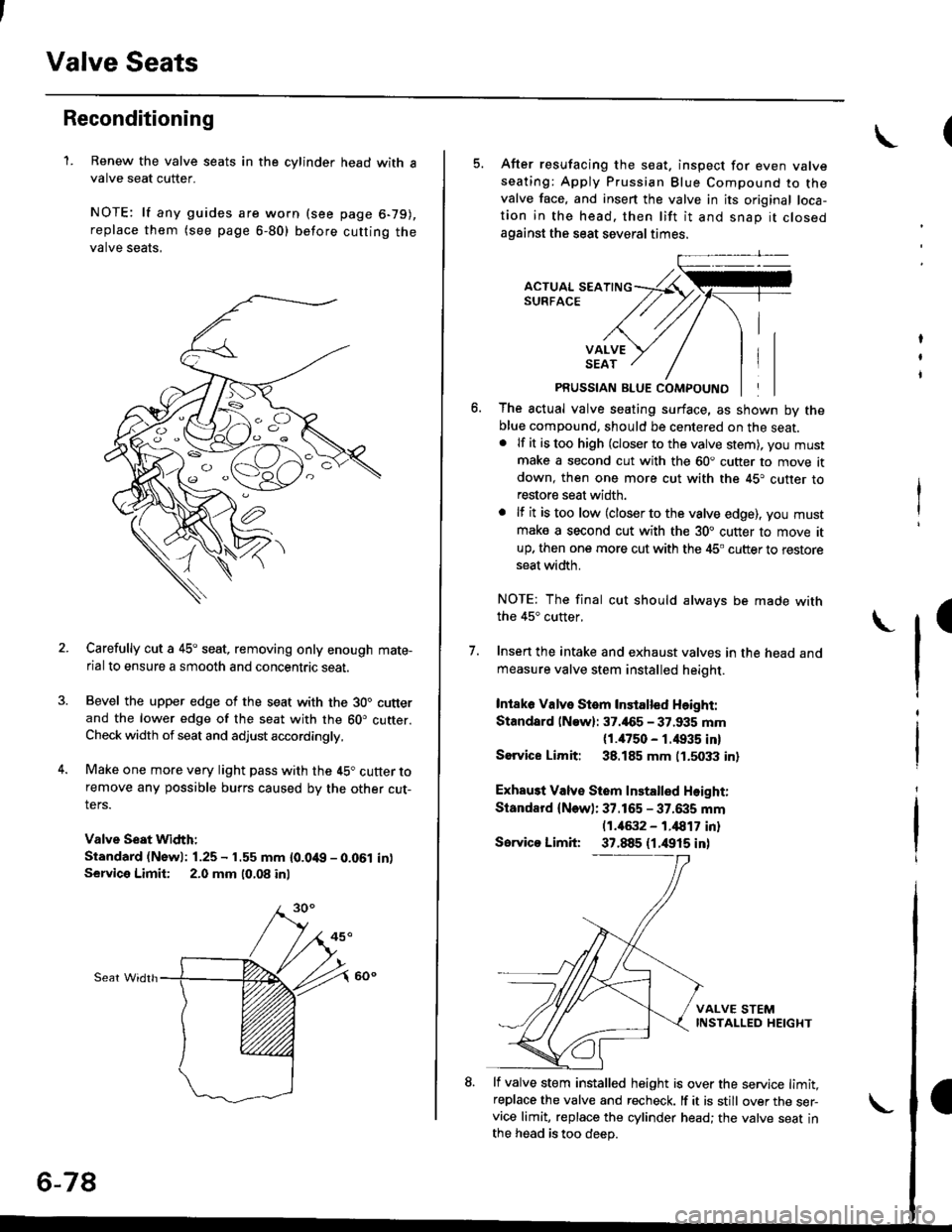
Carefully cut a 45o seat, removing only enough mate-
rial to ensure a smooth and concentric seat.
Bevel the upper edge of the seat with the 30" cutterand the lower edge of the seat with the 60. cutter.Check width of seat and adjust accordingly,
Make one more very light pass with the 45" cutter toremove any possible burrs caused bv the other cut-
ters.
Valve Seat Width:
Standard (Newl: 1.25 - 1.55 mm {0.0't9 - 0.061 in)Service Limii: 2.0 mm 10,08 inl
Sear Widrh
6-78
5. After resufacing the seat. inspect for even valveseating: Apply Prussian Blue Compound to thevalve face, and insert the valve in its original loca-tion in the head. then lift it and snap it closedagainst the seat several times.
PRUSSIAN BLUE COMPOUND
The actual valve seating surface, as shown by theblue compound, should be centered on the seat.. lf it is too high (closer to the valve stem), you mustmake a second cut with the 60. cutter to move itdown, then one more cut with the 45. cutter torestore seat width.
. lf it is too low (closer to the valve edge), you must
make a second cut with the 30. cutter to move itup. then one more cut with the 45. cutter to restoreseat width.
NOTE: The final cut should always be made withthe 45" cutter,
7. Insen the intake and exhaust valves in the head and
measure valve stem installed heioht.
Intaka Valve Stem Installed Height:
Standsrd lNaw): 37.465 - 37.935 mm(1./P50 - r.4935 inl
Sorvice Limit: 38.185 mm 0.5033 in)
Exhau3t Valv€ Stem Installed Height:
Standard (New): 37.165 - 37.6i|5 mm(1.46:t2 - 1.i1817 inl
Servico Limit 37.885 (1.4915 inl
lf valve stem installed height is over the service limit,replace the valve and recheck. lf it is still over the ser-vice limit, replace the cylinder head; the valve seat inthe h6ad is too deep.
(
Page 192 of 2189
Valves
1.
Installation
Coat the valve stems with oil. lnsert the valves into
the valve guides.
NOTE: Check that the valves move up and downsmoothly.
Installthe spring seats on the cylinder head.
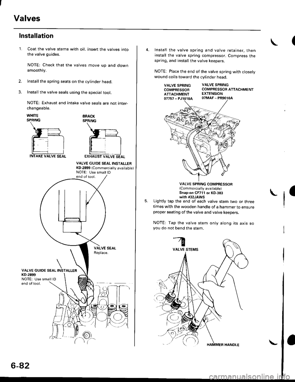
Install the valve seals using the special tool.
NOTE: Exhaust and intake valve seals are not inter-
changeable.
WHITESPRING
VALVE GUIDE SEAL INSTALLERKD-28)g (Commercially available)NOTE: Use small lDend of tool,
2.
BRACKSPRING
VALVE SEALReplace.
tNsTALLERVALVE GUIDE SEALKD-2899NOTE: Use small lDend of tool
(
4. lnstall the valve spring and valve retainer, theninstall the valve spring compressor. Compress thespring, and install the valve keepers.
NOTE: Place the end of the valve spring with closely
wound coils toward the cylinder head.
VALVE SpRtNG VALVE SPRTNG
COMpRESSOR COMPRESSORATTACHMENT
ATTACHMENT EXTENSTON
0775? _ pJlOl0A o?MAF - PR9010A
VALVE SPRING COMPRESSORlCommercially available)Snap-on CF711 or KD-3tXlwith #32JAWSLightly tap the end of each valve stem two or threetimes with the wooden handle of a hammer to ensureproper seating of the valve and valve keepers.
NOTE: Tap the valve stem only along its axis soyou do not bend the stem.
I
5.
Page 197 of 2189
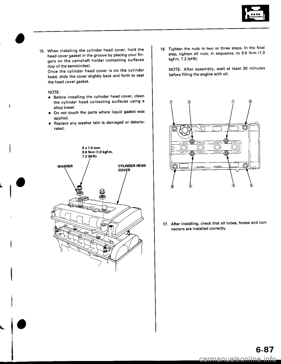
15. When installing the cylinder head cover, hold the
head cover gasket in the groove by placing your fin-
gers on the camshaft holder contacting surfaces
(toD of the semicircles).
Once the cylinder head cover is on the cylinder
head, slide the cover slightly back and forth to seat
the head cover gasket.
NOTE:
. Be{ore installing the cylinder head cover, clean
the cvlinder head contacting surfaces using a
shoP towel.
. Oo not touch the parts where liquid gasket was
applied.
. Replace any washer taht is damaged or deter'o-
rated.
t
\
6-A7
16. Tighten the nuts in two or three steps. In the final
step, tighten all nuts, in sequence, to 9 8 N'm {1 0
kgf.m, 7.2 lbf.ft).
NOTE: After assembly, wait at least 30 minutes
before filling the engine with oil.
After installing, check that all tubes' hoses and con-
nectors are installed correctly.17.
Page 214 of 2189
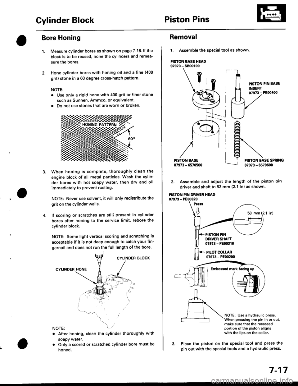
Cylinder BlockPiston Pins
Bore Honing
1.Measure cylinder bores as shown on page 7-16. lf the
block is to be reused, hone the cylinders and remea-
sure the bores.
Hone cylinder bores with honing oil 8nd a fine (400
grit) stone in a 60 degree cross-hatch pattern.
NOTE:
. Use only a rigid hone with 400 grit or finer stone
such as Sunnen, Ammco, or equivalent.
. Do not use stones lhat are worn or broken.
When honing is complete, thoroughly clean the
engine block of all metal particles. Wash the cylin-
der bores with hot soapY water, then dry and oil
immediately to prevent rusting.
NOTE: Never use solvent. it will only redistribute the
grit on the cylinder walls.
lf scoring or scratches are still present in cylinder
bores after honing to the service limit, rebore the
cylinder block.
NOTE: Some light vertical scoring and scratching is
acceptable if it is not deep enough to catch your fin-
gernail and does not run the full length of the bore.
CYLINOES BLOCK
CYLINDER
NOTE:
. After honing, clean the cylinder thoroughly with
soapy warer.
. Onlv a scored or scratched cylinder bore must be
noneo.
Removal
l. Assemble the special tool as shown.
PISTON BASE HEAD07973 - SBtx)too
ft
PISTON PIN BASE
INSERT01973 - PE00'0)
ptn
NOTEi Us6 a hydraulic press.When pressing the pin in or out.make sure that the recesssdportion of the piston alignswith the lips on the collar.
rg
g\
lj*N*,""
2. Assemble and adjust the length of the piston
driver and shaft to 53 mm (2.1 inl as shown.
PISTON PIN DRIVER HEAD07973 - PE00320
Proat
0
PISTON PINDRIVER SHAFT0t973 - PEqr310
PILOT COLLAR07973 - PE00200
3. Place the piston on the sp€cial tool and press the
pin out with the special tools and a hydraulic press.
Emboss6d mark facing up
7-17
Page 219 of 2189
Piston RingsCrankshaft Oil Seal
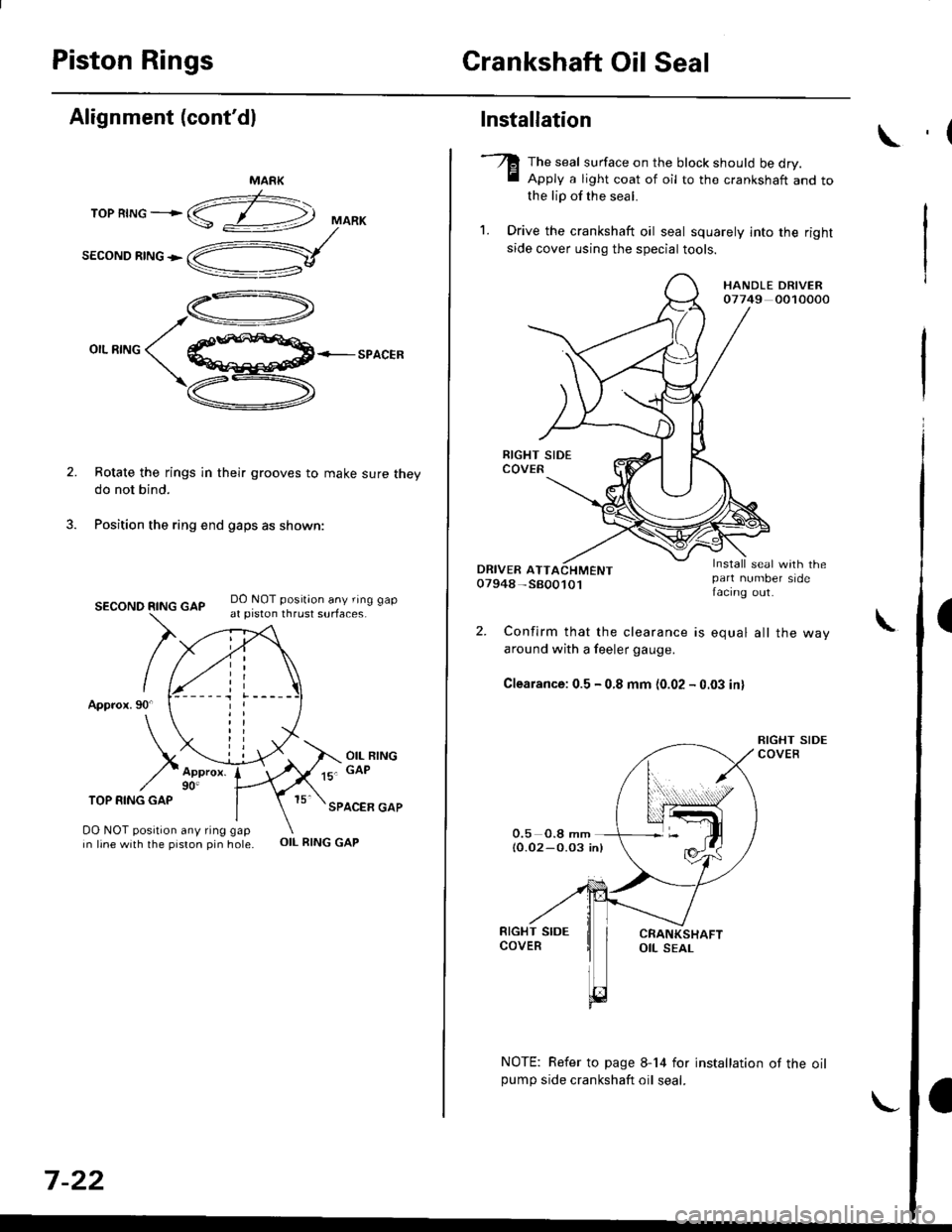
Alignment (cont'dl
TOP RING ---.>
SECOND RING >
MARK
,a-)
/\_4
o,.r^o( qffi<--sPACER
\Z-.
v
Rotate the rings in their grooves to make sure theydo not bind.
Position the ring end gaps as shown:
DO NOT position any ring gapat piston thrust surfaces.
DO NOT position any ring gapin line with the piston pin hole.OIL RING GAP
SECOND RING GAP
Approx.90
TOP RING GAP
7-22
Installation
The seal surface on the block should be dry.Apply a light coat of oil to the c.ankshaft and tothe lip of the seal.
1. Drive the crankshaft oil seal squarely into the right
side cover using the special tools.
HANDLE DRIVER07749 0010000
seal with thepan number sidefacing out.
Confirm that the clearance is equal all the way
around with a feeler gauge.
Clearance:0.5 - 0.8 mm (0.02 - 0.03 inl
NOTE: Refer to page 8-14 for installation of the oilpumo side crankshaft oil seal.
,(
\
Page 223 of 2189
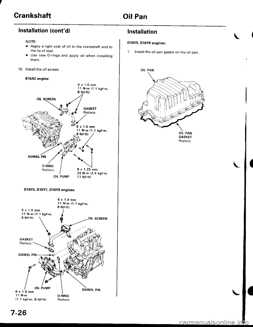
CrankshaftOil Pan
Installation (cont'd)
NOTE:
. Apply a light coat of oil to the crankshaft and iothe lip of seal.. Use new O-rings and apply oil when installingthem.
10. lnstallthe oil screen.
816A2 engine:
6 x 1.O mml l N'm (1 .1 kgl.m,8 tbt.Irl
,.//
{ / cor*rt(..ao Replace.
t(^^
11 N.m 11 .1 kgf.m,a lbl'ltl ,/.rB tbt4tl /
*P/
& ^/t
O.RINGReplace.
OtL PutitP
D16Y5, D16Y7, D16Y8 engines:
24 N.m (2.4 kgf.m,'17 lbl.fr)
kgf.m,
OIL SCREEN
6 x 1.0 mm1 1 N.m {1 .1 kgf.m,
6x1.0mm11 N.m {1.18 tbt.rr)
I
Ia lbf.fr)
DOWEL PIN
rT
lle/ OIL PUMP6 x 1.0 mm11 N.ml l.1 kgf'm, a lbf.frl
7-26
Installation
D16Y5, Dl6Yg engines:
1. Install the oil pan gasket on the oil pan.
OIL PANGASKETReplace.
OIL PAN
I
Page 226 of 2189
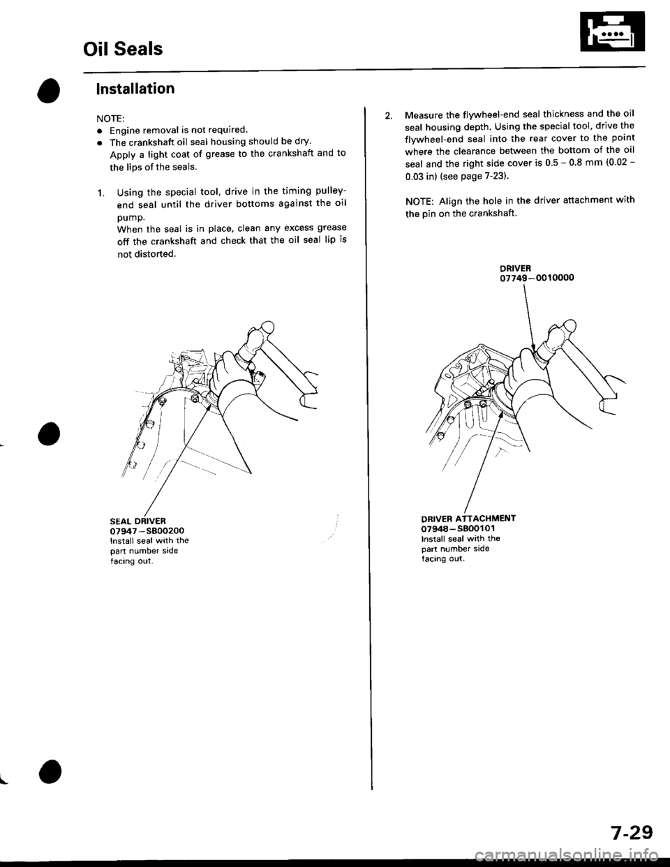
Oil Seals
lnstallation
NOTE:
. Engine removal is not required.
. The crankshaft oil seal housing should be dry.
Apply a light coat of grease to the crankshaft and to
the lips of the seals.
1. Using the special tool, drive in the timing pulley-
end seal until the driver bottoms against the oil
pump.
When the seal is in place, clean any excess grease
off the crankshaft and check that the oil seal lip is
not distorted.
07947 -S800200
lnstall seal with thepart number sadefacing out.
I
2. Measure the flvwheel-end seal thickness and the oil
seal housing depth. Using the special tool. drive the
flywheel-end seal into the rear cover to the point
where the clearance between the bottom of the oil
seal and the right side cover is 0.5 - 0.8 mm (0.02 -
0.03 in) (see page 7-23).
NOTE: Align the hole in the driver attachment with
the Din on the crankshaft.
DRIVER ATTACHMENT0794a-s800101lnslall seal with thepart number sidefacing out.
DRIVER07749-0010000
7 -29
Page 234 of 2189
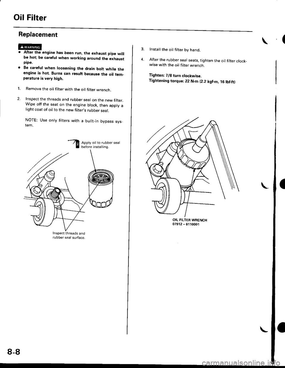
Oil Filter
Replacement
After the engine has been run, the exhaust pipe willbe hot; be careful when working around ihe exhaustpipe.
Be careful when loosening the drain bolt whils theengine is hot. Burns can resuh because the oil tem-peratu16 is very high.
Remove the oil filter with the oil filter wrencn.
Inspect the threads and rubber seal on the new filter.Wipe off the seat on the engine block, then apply alight coat of oil to the new filter,s rubber seal.
NOTE: Use onty fitters with a built-in bypass sys,tem.
Apply oil to rubber sealbefore installing.
l.
Inspect threads andrubber seal surface.
8-8
Install the oil filter by hand.
After the rubber seal seats, tighten the oil filter clock_wise with the oil filter wrench.
Tighten: 7/8 tu.n clockwise.
Tightening tolque: 22 N.m (2.2 kgt.m, 16lbf.ft)
OIL FILTER WRENCH07912 - 6110001
Page 240 of 2189
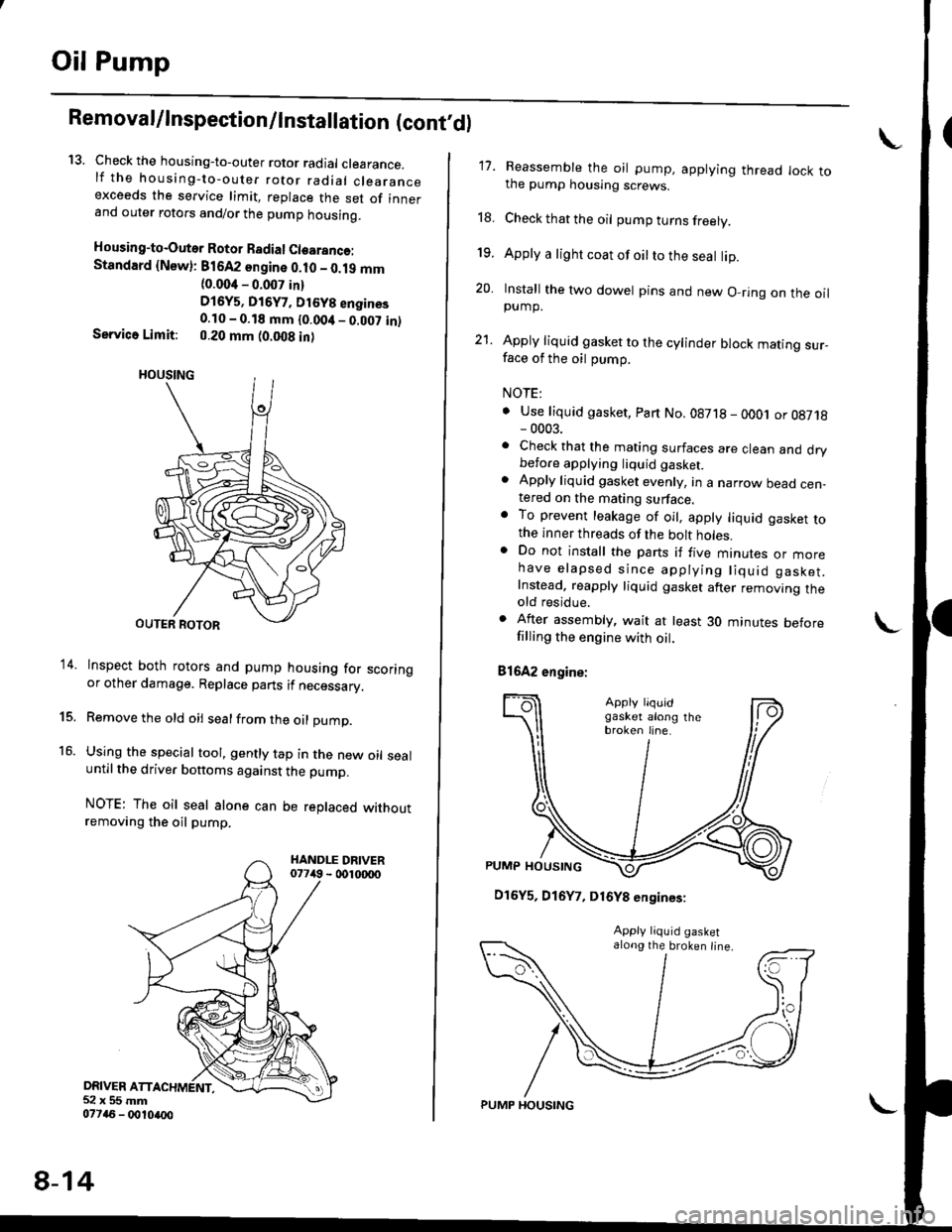
Oil Pump
RemovaUlnspection/lnstallation (cont'dl
13. Check the housing-to-outer rotor radial clearance.lf the housing-to-outer rotor radial clearanceexceeds the service limit, replace the set of innerand outer rotors and/or the pump housing.
Housing-to-Outer Rotor Badial Clearanco:Standard {Newl: 816A2 sngine 0.10 - 0.19 mm(0.004 - 0.007 in)
D16y5, Di6y7, Dt6y8 engines0.10 - 0.18 mm {0.00it _ 0.007 in)Service Limit: 0.20 mm (0.008 in)
lnspect both rotors and pump housing for scoringor other damage. Replace parts if necessary.
Remove the old oil sealfrom the oil pump.
Using the special tool, gently tap in the new oil sealuntil the driver bottoms against the pump.
NOTE: The oil seal alone can be replaced withoutremoving the oil pump.
DRIVER ATT52x55mm077a6 - 0010ao0
14.
15.
16.
8-14
PUMP HOUSING
17. Reassemble the oil pump, applying thread lock tothe pump housing screws.
18. Check that the oil pump turns freely.
19. Apply a light coat of oilto the seal lip.
20. Install the two dowel pins and new O-ring on the oilpump.
21. Apply liquid gasket to the cylinder block mating sur_face of the oil pump.
NOTE:
. Use liquid gasket, Part No.08718 - oOOj or 08718- 0003.. Check that the mating surfaces are clean and drybefore applying liquid gaskel. Apply liquid gasket evenly, in a narrow bead cen-tered on the mating surface.o To prevent leakage of oil, apply liquid gasket tothe inner threads of the bolt holes.. Do not install the parts if five mtnures or morehave elapsed since applying liquid gasket.Instead. reapply liquid gasket after removing theold residue.
. After assembly, wait at least 30 minutes beforefilling the engine with oil.
81642 engine:
\
D16Y5, D16Y7, D16Y8 engines:
along the broken line.