Light switch HONDA CIVIC 2000 6.G Workshop Manual
[x] Cancel search | Manufacturer: HONDA, Model Year: 2000, Model line: CIVIC, Model: HONDA CIVIC 2000 6.GPages: 2189, PDF Size: 69.39 MB
Page 2056 of 2189
Security System (cont'd)
Security Control Unit Troubleshootlng
lf a faulty security system has one of the symptoms below, turn to the page listed and follow the appropriate
troubleshooting procedure. lf the symplom seems related to an input problem, or is not covered by the
troubleshooting procedures, do the Input Tests on page 133-15. Refer to the circuit schematic on pages 133
through 133-12 as needed.
Symptom lndex
Security Sysiem Does Not Work In Any Mode (HX, LX, EX)
Security System Does Not Work In Any Mode (CX, DX)
Security System Does Not Arm (CX, DX)
Security System Does Not Arm (HX, LX, EX, DX-V, SD
Security System Does Not Disarm With The Transmitler
(HX, LX, EX, DX-V, Si)
Security System Does Not Disarm (CX, DX) . . . .
Security System Does Not Disarm With The Valet Switch
c96-'�98 HX, LX, EX) .
Security System Does Not Disarm With The Valet Switch ('99 models) . . .
Security System Do€s Not Work In The Valet Mode
('96.,98 HX, LX, EX) .
Security System Does Not Work InTheValetMode ('99 models) ........
Security System Alaim Does Not Trigger When The System ls Armed
And The Trunk Or A Door ls Ooened
Security System Does Not'Beep" 3 Times When The System ls Armed
With The Trunk Or A Door Open (HX, LX, EX, DX-V Si)
Parking Lights Do Not Flash (CX, DX)
Parking Lights Do Not Flash (HX, LX, EX, DX-V Si)
Security System Status LED Stays On (HX, LX, EX, DX-V Si)
Security System Status LED Does Not Com€ On (HX, LX, EX, DX-V, Si) .
Starter Cut Does Not Work Properly ('96198 HX, LX, EX, DX-V, SD . . . . . .
Starter Cut Does Not Work Properly (CX, DX) . . . . .
Hom Does Not Sound When Alarm ls Triggered
Input Tests
Page 133-17
Page 133-18
Page 133-18
Page 133-19
Page 133-20
Page 133-20
Page 133-21
Page 133-22
Page 133-21
Page 133-22
Page 133-23
Page 133-23
Page 133-24
Page 133-25
Page 133-26
Page 133-26
Page 133-27
Page 133-28
Page 133-29
Page 133- l5
133-14
Page 2058 of 2189
Security System (cont'd)
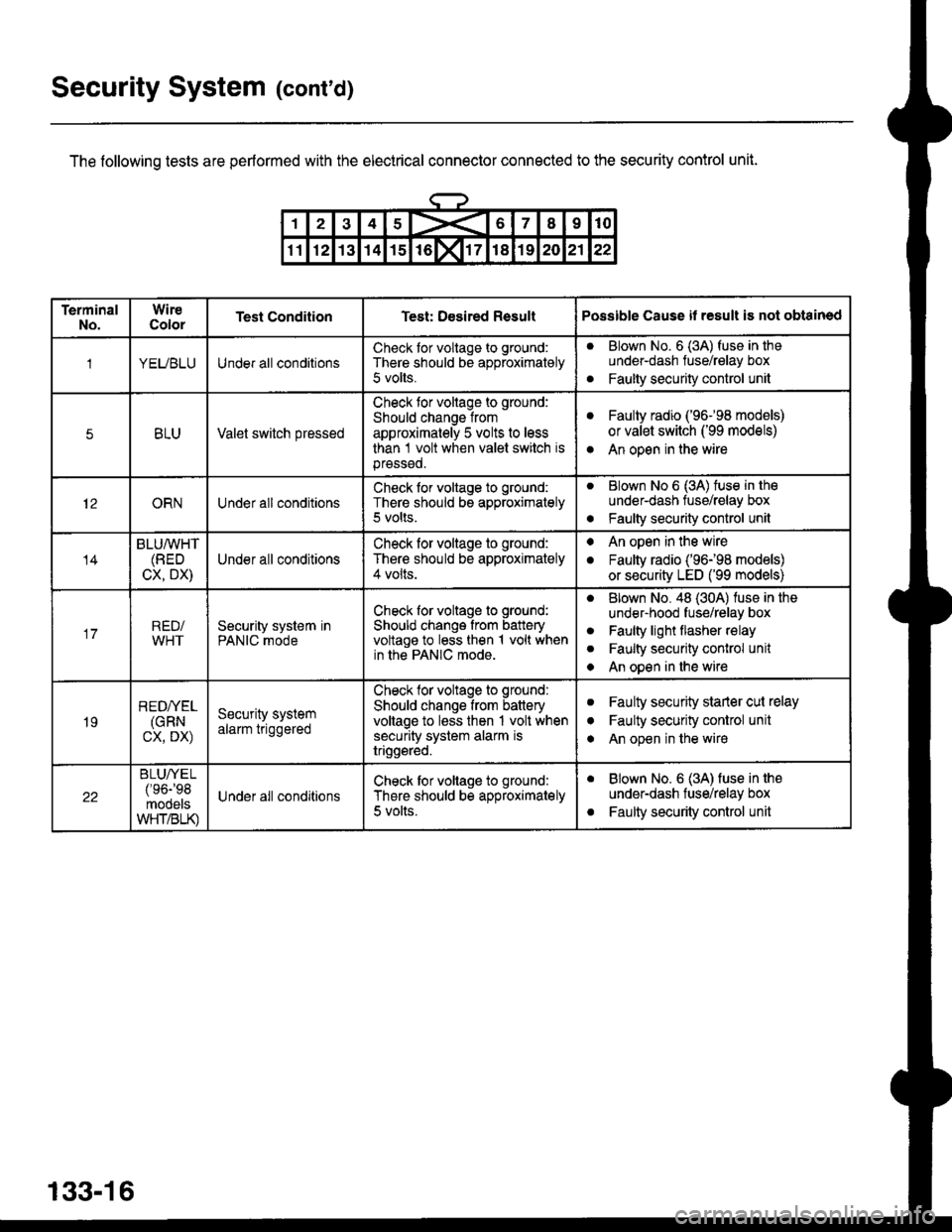
The following tests are performed with the electrical connector connected to the security control unit.
133-16
TerminalNo.WireColorTest ConditionTest: Desired ResultPossible Cause il result is not obtained
1YEUBLUUnder all conditionsCheck tor voltage to ground:
There should be approximately
5 volts.
aBlown No. 6 (3A) fuse in theunder-dash fuse/relay box
Faulty security control unita
5BLUValet switch pressed
Check tor voltage to ground:
Should change from
approximately 5 volts to less
than 1 volt when valet switch isprsssed.
aFaulty radio ('96-98 models)
or valet switch ('99 models)
An open in the wirea
12ORNUnder all conditionsCheck for voltage to ground:
There should be approximately5 volts.
aBlown No 6 (3A) tuse in tho
under-dash tuse/relay box
Faulty security control unito
14
BLU/WHT(BED
CX, DX)Under all conditions
Check for voltage to ground:
There should be approximately4 volts.
. An open in the wire
. Faulty radio ('96198 models)
or security LED ('99 models)
17RED/WHTSecurity system inPANIC mode
Check for voltage to ground:
Should change from batteryvoltage to less then 1 volt whenin the PANIC mode.
aBlown No. 48 (30A) luse in the
under-hood fuse/relay box
Faulty light flasher relay
Faulty security conlrol unit
An open in the wire
a
a
a
19
REDI/EL(GRN
cx, DX)
Security systemalarm triggered
Check tor voltags to ground:
Should change from batteryvoltage to less then 1 volt whensecurity system alarm istriggsred.
aFaulty security starler cut relay
Faulty security control unit
An open in the wire
I
a
22
BLUA/EL/'oa-'oq
mooelsWHT/BLK)
Under all conditionsCheck tor voltage to ground:
There should be approximately
5 volts.
aBlown No. 6 (3A) fuse in the
under-dash fuse/relay box
Faulty security control unita
Page 2060 of 2189
Security System (cont'd)
Security System Does Not Work ln Any
Mode (CX, DX)
1. ls luse 54 (in the under-hood fuse box) OK?
Yes - Go to the next step.
No - Repiace the blown fuse, then go to the
next step.
2. ls the fuse in the securiiy in-line fuse holder OK?
Yes - Go to the next step.
No - Replace the blown fuse, then go to next
srep.
3. Does either fuse blow again?
Yes - Locate and repair the short.
No - Retest the system.
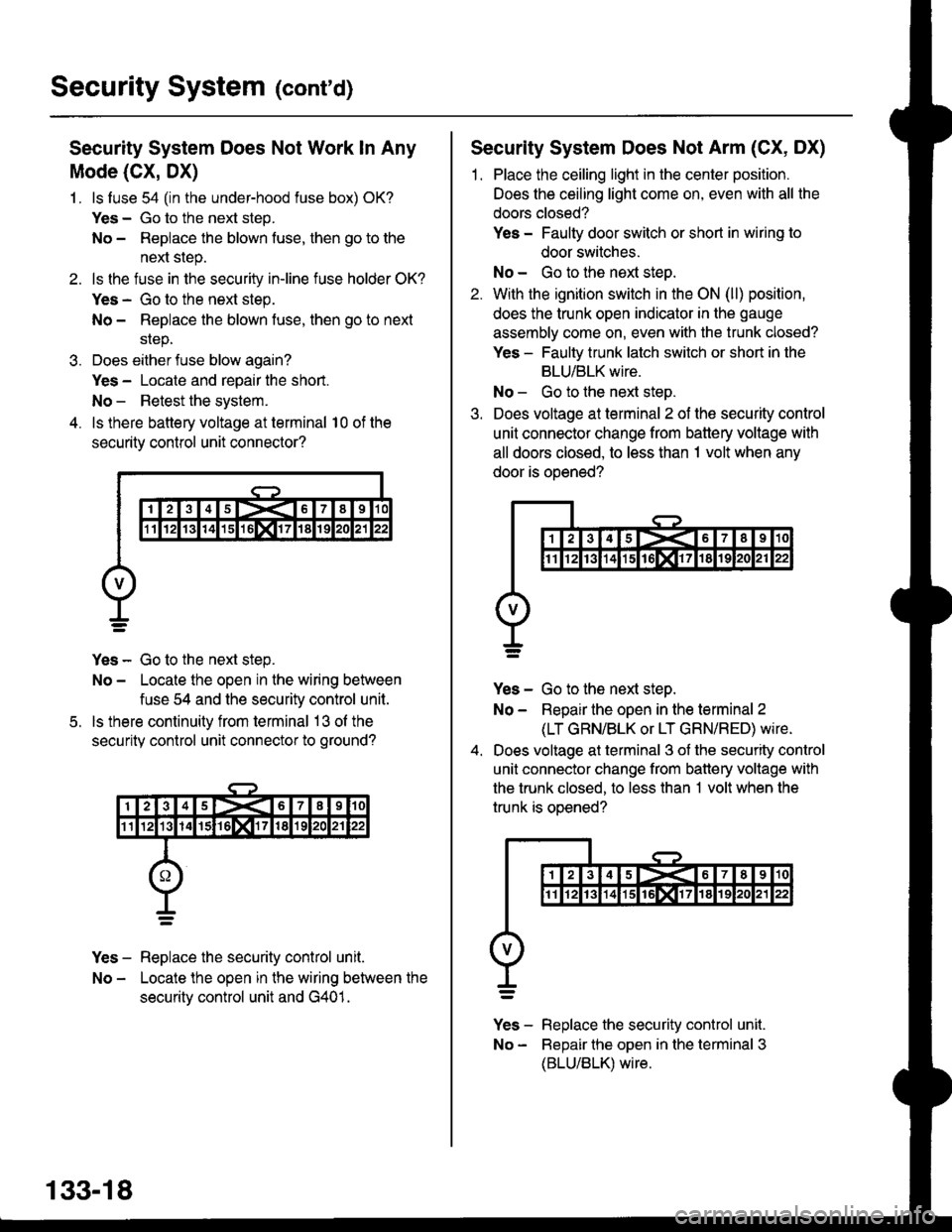
4. ls there battery voltage at terminal 10 of the
security control unit connector?
Yes - Go to the next step.
No - Locate the open in the wiring between
fuse 54 and the security control unit.
ls there continuity from terminal 13 ol the
security control unit connector to ground?
Yes - Replace the security control unit.
No - Locate the open in the wiring between the
securitv control unit and G401.
5.
133-18
Security System Does Not Arm (CX, DX)
1. Place the ceiling light in the center position.
Does the ceiling light come on, even with all the
doors closed?
Yes - Faulty door switch or short in wiring to
door switches.
No - Go to the next steo.
2. With the ignition switch in the ON (ll) position,
does the trunk open indicator in the gauge
assembly come on, even with the trunk closed?
Yes - Faulty trunk latch switch or short in the
BLU/BLK wire.
No - Go to the next step.
3. Does voltage at terminal 2 of the security control
unit connector change from battery voltage with
all doors closed, to less than 1 volt when any
door is ooened?
Yes - Go to the next step.
No - Repair the open in the terminal 2
(LT GRN/BLK or LT GRN/RED) wire.
Does voltage at terminal 3 of the security control
unit connector change from battery voltage with
the trunk closed, to less than 1 volt when the
trunk is oDened?
v]" - R"pt"." tne security control unit.
No - Bepair the open in the terminal 3
(BLU/BLK) wire.
Page 2065 of 2189
Security System Alarm Does Not Trigger
When The System ls Armed And The
Trunk Or A Door ls Opened
Security System Does Not "Be€p" 3 Times
When The System is Armed With The Trunk
Or A Door Open (HX, LX, EX, Dx-V SD
1. Place the ceiling light in the center position, then
open and close the doors one at a time. Do all
the doors operate the ceiling light properly?
Yes - Go to the next steo.
No - Repair the ceiling light circuit.
With the ignition switch in the ON (ll) position,
does the trunk open indicator in the gauge
assembly come on with the trunk open?
Yes - Go to the next step.
No - Faulty trunk latch switch or an open in the
BLU/BLK wire.
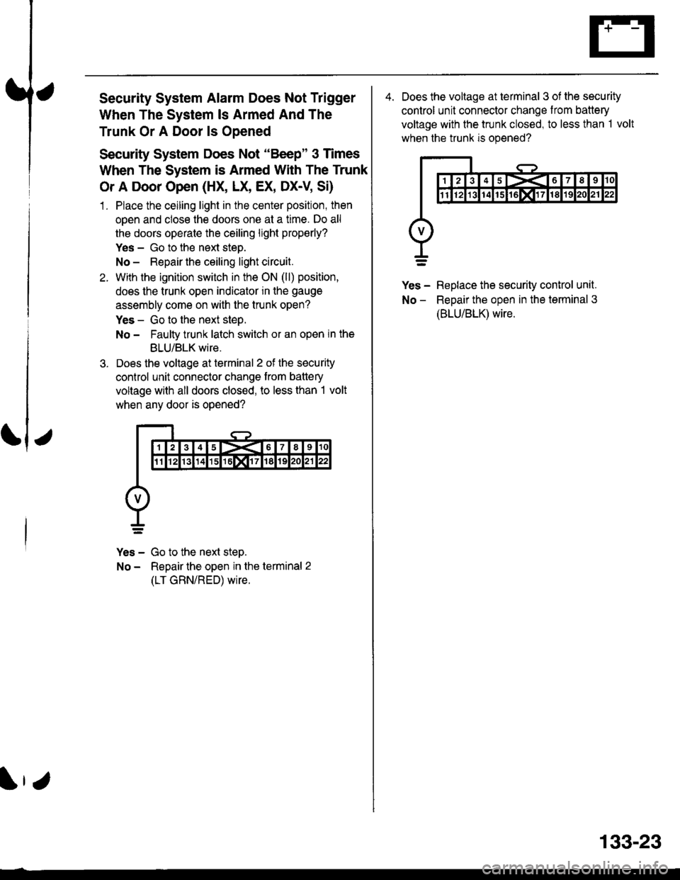
Does the voltage at terminal 2 of the security
control unit connector change trom battery
voltage with all doors closed, to less than I volt
when any door is opened?
Yes - Go to the next step.
No - Repair the open in the terminal 2
(LT GRN/RED) wire.
4. Does the voltage at terminal 3 of the security
control unit connector change from battery
voltage with the trunk closed, to less than 1 volt
when the trunk is opened?
Yes - Replace the security control unit.
No - ReDair the oDen in the terminal 3
(BLU/BLK) wire.
133-23
Page 2066 of 2189
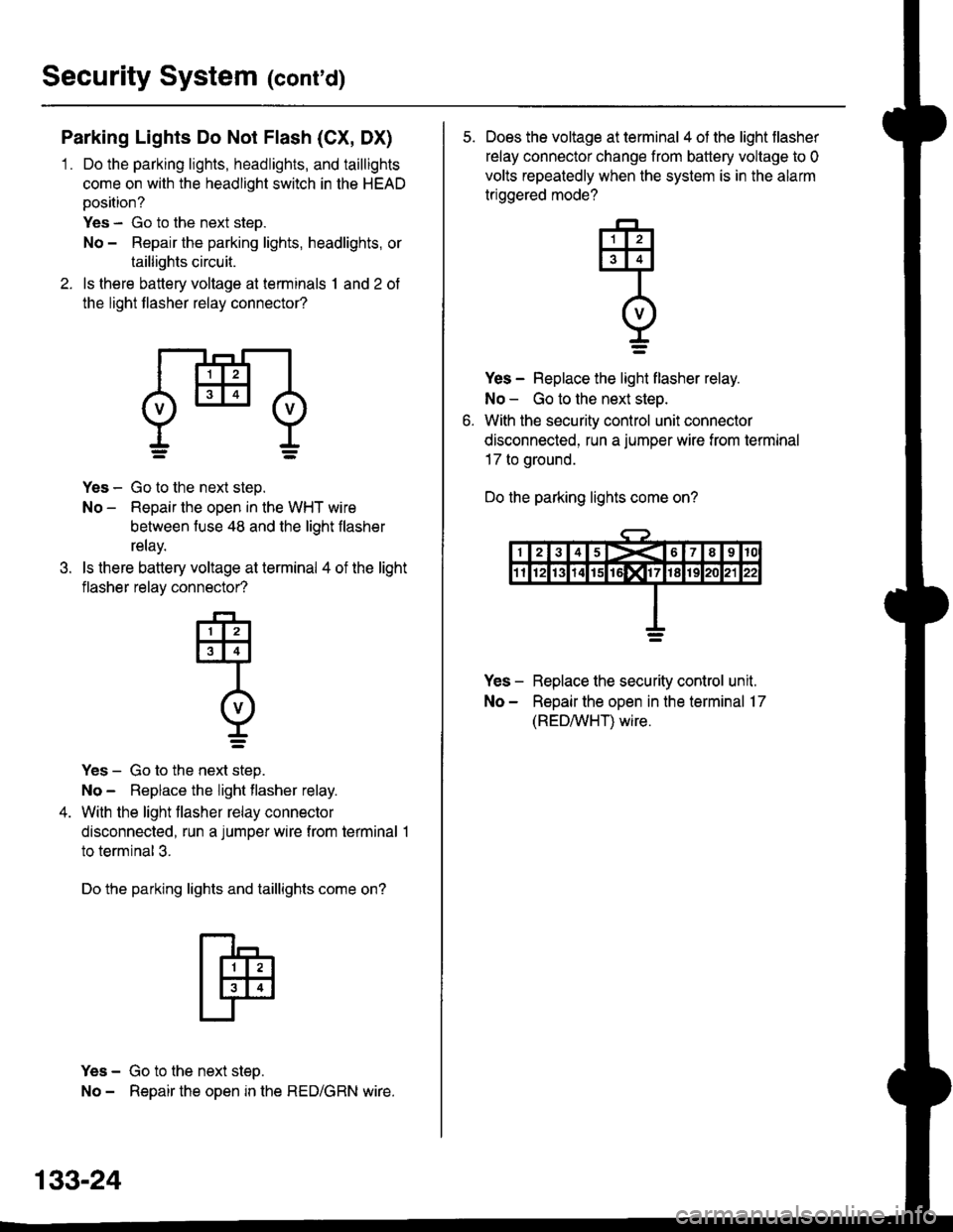
Security System (conrd)
Parking Lights Do Not Flash (CX, DX)
1 . Do the parking lights, headlights, and taillights
come on with the headlight switch in the HEAD
position?
Yes - Go to the next step.
No - Repair the parking lights, headlights, or
taillights circuit.
2. ls there battery voltage at terminals 1 and 2 of
the light flasher relay connector?
dHl
.t.
Yes - Go to the next step.
No - Repair the open in the WHT wire
between fuse 48 and the light flasher
relay.
ls there battery voltage at terminal 4 of the light
flasher relay connector?
-F-,
tlllJt3l4l
Intvl
r=
Yes - Go to the next step.
No - Replace the light flasher relay.
With the light flasher relay connector
disconnected, run a jumper wire from terminal 1
to terminal 3.
Do the parking lights and taillights come on?
Yes - Go to the next step.
No - Repair the open in the RED/GRN wire.
133-24
5. Does the voltage at terminal 4 of the light flasher
relay connector change from battery voltage to 0
volts repeatedly when the system is in the alarm
triggered mode?
Yes - Replace the light flasher relay.
No - Go to the next step.
With the security control unit connector
disconnected, run a jumper wire from termrnal
17 to ground.
Do the parking lights come on?
Yes - Replace the security control unit.
No - Repair the open in the terminal 17
(REDAIVHT) wire.
q
I=
Page 2067 of 2189
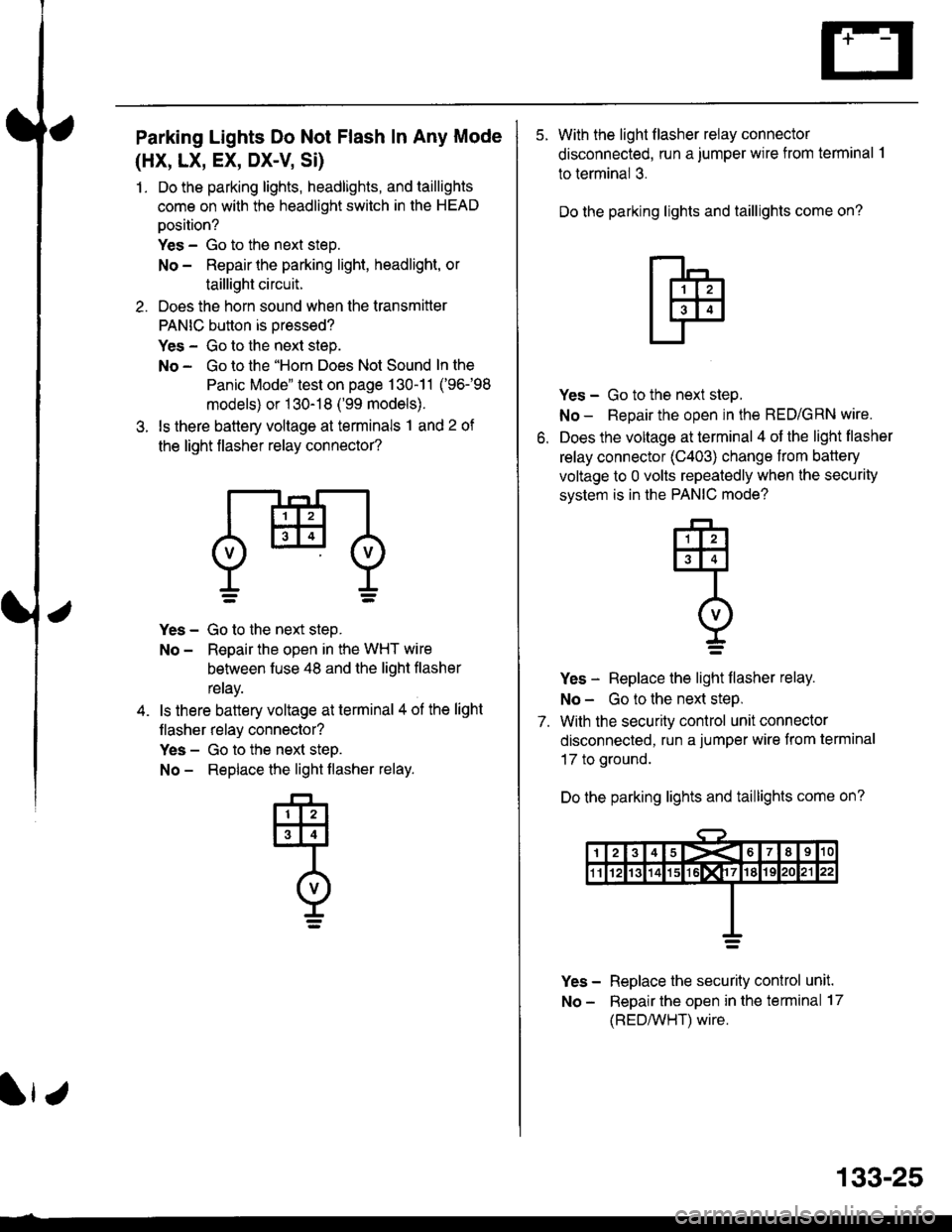
Parking Lights Do Not Flash In Any Mode
(HX, LX, EX, DX-V Si)
1. Do the parking lights, headlights, and taillights
come on with the headlight switch in the HEAD
oosition?
Yes - Go to the next steo.
No - Repair the parking light, headlight, or
taillight circuit.
2. Does the horn sound when the transmitter
PANIC button is oressed?
Yes - Go to the next step.
No - Go to the "Horn Does Not Sound In the
Panic Mode" test on page 130-11 ('96-98
models) or 1 30-18 ('99 models).
3. ls there battery voltage at terminals 1 and 2 of
the light flasher relay connector?
Yes - Go to the next step.
No - Reoair the open in the WHT wire
behveen fuse 48 and the liqht flasher
reray.
ls there battery voltage at terminal 4 ol the light
flasher relay connector?
Yes - Go to the next steD.
No - Replace the light flasher relay.
133-25
5. With the light flasher relay connector
disconnected, run a jumper wire from terminal .l
to terminal 3.
Do the parking lights and taillights come on?
o.
Yes - Go to the next step.
No - Repair the open in the RED/GRN wire.
Does the voltage at terminal 4 of the light flasher
relay connector (C403) change from battery
voltage to 0 volts repeatedly when the security
svstem is in the PANIC mode?
Yes - Replace the light flasher relay.
No - Go to the next steP.
7. With the security control unit connector
disconnected, run a jumper wire from terminal
17 to ground.
Do the parking lights and taillights come on?
Yes - Replace the security conlrol unit.
No - Repair the open in the terminal 17
(REDMHT) wire.
q
I=
Page 2108 of 2189
-
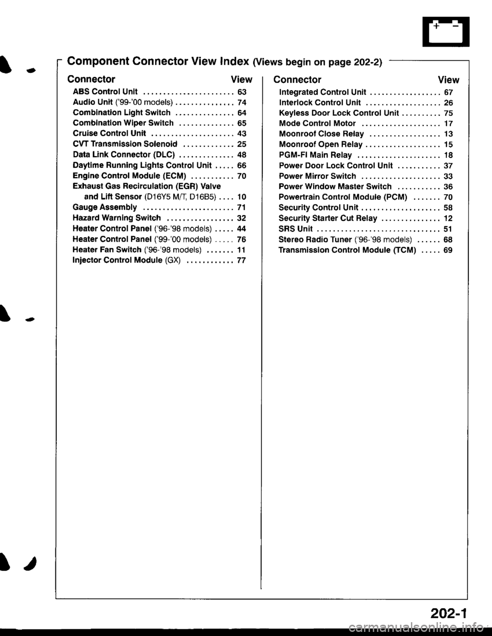
Component Connector View Index (Views begin on page 202-21
Connector View
ABS Control Unit........ ......63
Audio Unit ('99-'00 models) ......74
Combination Light Switch . . . . . . . . . . . . . . . 64
Combination Wiper Switch . . . . . . . . . . . . . . 65
Cruise Control Unit.... .....43
C\TTTransmission Solenoid ............. 25
Data Link Connector (DLC) ..... 48
Daytime Runnlng Lights Control Unit ..... 66
Engine control Module (ECM) ...........70
Exhaust Gas Recirculation (EGR) Valve
and Lift Sensor (D16Y5 Mfl, D1685) . . . . 10
Gauge Assembly .............71
HazardWarnlngSwitch,,. .,,,...,,,,... 32
Heater Control Panel ('96-'98 models) .....44
Heater Control Panel ('99-'00 models) ...., 76
Heater Fan Switch ('96-'98 models) ,,,.... 11
fniector Control Module (GX) ............77
I/
202-1
Connector View
Integrated Control Unit .......,. 67
f nterfock Control Unit .... ...... 26
Keyfess Door Lock Control Unit . . . . , . . . . . 75
Mode Control Motor ... ........'17
Moonroof Close Relay .. .......13
Moonroof Open Relay ... .......15
PGM-FI Main Relay .. .......... 18
Power Door Lock Conlrol Unil ..... ...... 37
Power Mirror Switch .,... ...... 33
Power Window Master Switch .,.........36
Powertrain Control Module (PCM) .......70
Security Control Unit ..., ..,,... 58
Security Starter Cut Belay ... ...,,,....,, 12
SRS Unit ............. 51
Stereo Radio Tuner ('96-'98 models) ...... 68
Transmission Control Module CICM) .....69
Page 2109 of 2189
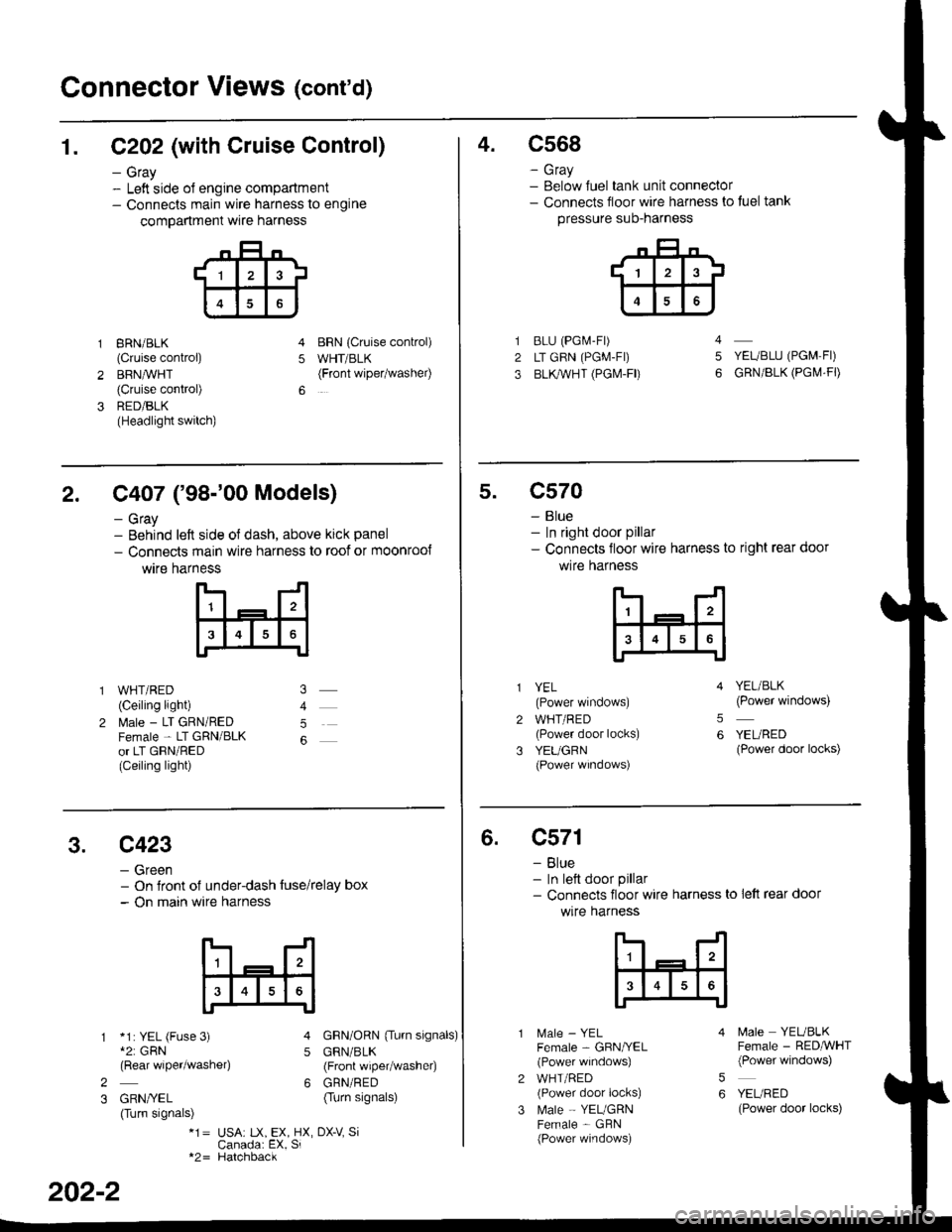
Connector Views (cont'd)
1. C202 (with Cruise Control)
- Gray- Left side ol engine compartment- Connects main wire harness to engine
compartment wre harness
gRN/BLK
(Cruise control)
BRN,ryVHT(Cruise control)
RED/BLK(Headlight switch)
BRN {Cruise conkol)
WHT/BLK(Front wipetwashel)5
4.c568
- Gray- Below Juel tank unit connector- Connects floor wire harness to tuel tank
pressure suo-narness
BLU (PGi.4-Fr)
LT GRN (PGM-FI)
BLl(WHT (PGI\4-FD
YEUBLU (PGM,FI)
GRN/BLK (PGI\,4.FD
4
5
2. C407 ('98-'00 Models)
- Gray- Behind left side ol dash, above kick panel
- Connects main wire harness to roof or moonroo{
wtre harness
WHT/RED(Ceiling light)
l\4ale - LT GRN/REDFemale - LT GRN/BLKor LT GRN/RED(Ceiling light)
5
5.c570
- Blue- In right door pillar- Connects floor wire harness to right rear door
wlre hafness
2
3
YEL(Power windows)
WHT/RED(Power door locks)
YEUGRN(Power wrndows)
YEL/BLK(Power windows)
YEURED(Power door locks)
5
6
3.c423
- Green- On Jront of under-dash tuse/relay box- On main wire harness
*1: YEL (Fuse 3)*2: GRN(Rear wiper/washe4
GRN/YEL(Turn signals)
GRN/ORN {Tu.n signals)
GRN/BLK(Front wiper/washer)
GRN/RED(Turn signals)
5
62
3
*1= USA: tX, EX, HX, DX-V SiCanada: EX, Si*2= Hatchback
202-2
6.c571
- Blue- In lett door pillar- Connects floor wire harness to lett rear door
wlre harness
MaIe _ YELFemale - GBN/YEL(Power windows)
WHT/RED(Power door locks)
Male - YEUGRNFemale - GBN(Power windows)
5
6
N4ale YEUBLKFemale - RED,ryVHT(Power windows)
YEURED(Power door locks)
Page 2110 of 2189
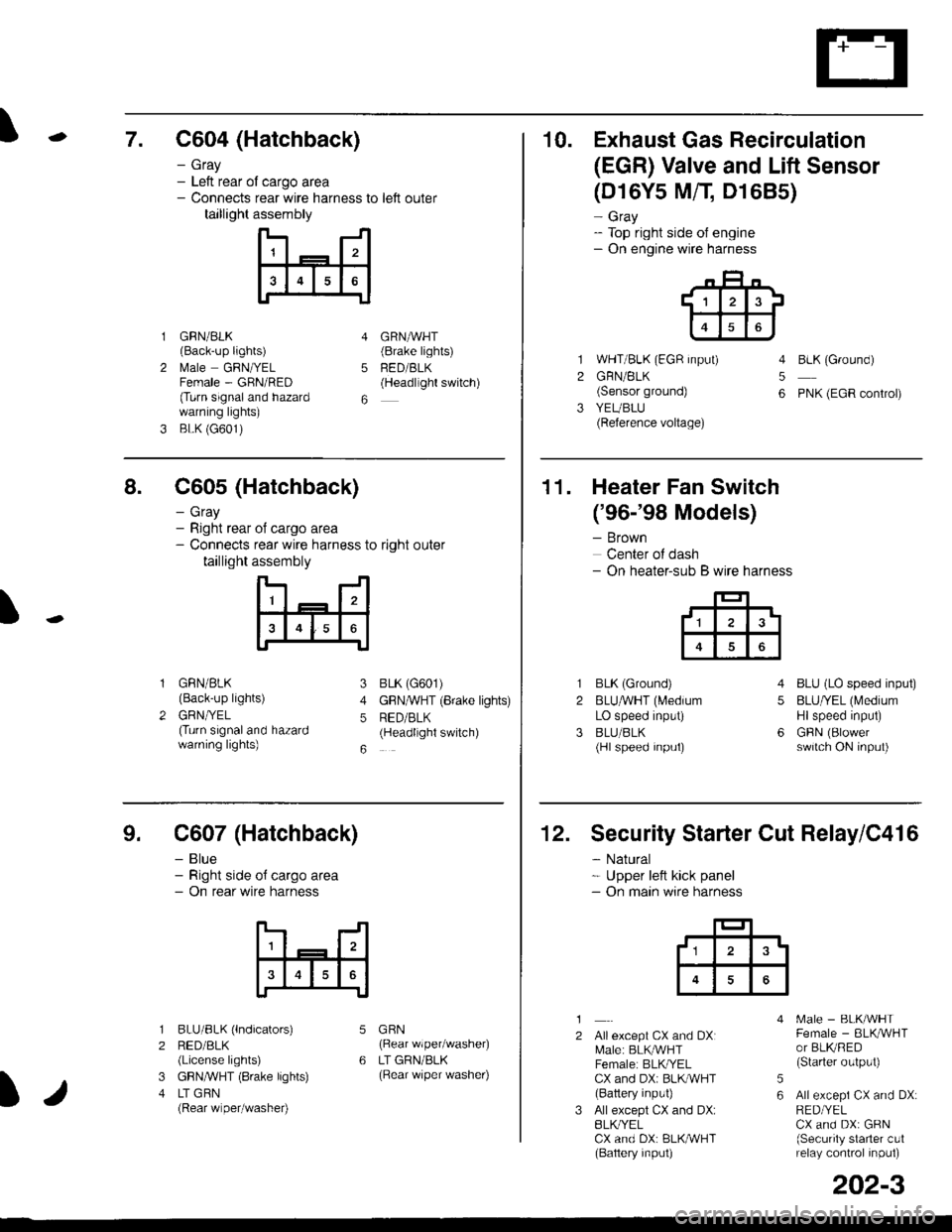
\7. C604 (Hatchback)
GRN/BLK(Back-up lights)
l\4ale GRNIYELFemale - GRN/RED(Turn signaland hazardwarning lights)
BLK (G601)
- Gray- Left rear ol cargo area- Connects rear wire harness to left outer
taillight assembly
4
5
6
1
2
GRNAVHT(Brake lights)
FED/BLK(Headllght switch)
10. Exhaust Gas Recirculation
(EGR) Valve and Lift Sensor
1
2
3
(D16Y5 MfI D1685)
- Gray- Top right side of engine- On engine wire harness
WHT/BLK (EGR input)
GRN/BLK(Sensor ground)
YEUBLU(Reference voltage)
4
5
6
BLK (Ground)
PNK (EGR control)
of cargo area
rear wire harness to right outer
assembly
n- -n
a t | _ a2a
l3I4t5tttl
IJ
I
8. C605 (Hatchback)
- Gray- Right rear- Connects
taillight
GRN/BLK(Back-up lights)
GRNTYEL(Turn signaland hazardwarning lights)
3
4
5
6
1
2
BLK (G601)
GFNAVHT (Brake lights)
RED/BLK(Headlight switch)
11. Heater Fan Switch
('96-'98 Models)
- Brown
Center of dash- On heater-sub B wire harness
BLK (Ground)
BLUAVHT (L4edium
LO speed input)
BLU/BLK(Hl speed input)
4
5
6
1
2
3
BLU (LO speed input)
BLU/YEL (Medium
Hlspeed input)
GFIN (Blowerswitch ON input)
9. C607 (Hatchback)
- Blue- Right side o{ cargo area- On rear wire harness
BLU/BLK (lndicators)
RED/BLK(License lights)
GBN,ryVHT (8rake lights)
LT GBN(Rear wiper/washe0
5
6
1
2
3
4
GRN(Rear wiper/washer)
LT GRN/BLK(Rear \/iper washer)
)/
202-3
12. Security Starter Cut Relay/C416
- Natural* Upper left kick panel- On main wire harness
1
2Allexcept CX and DXI[,4ale: BLK,^r'r'HTFemale: BLKI/ELCX and DXi BLI(WHT(Battery input)
All except CX and DX:BLK^/ELCX and DX: BLK/WHT(Baftery input)
[.4ale - BLK/WHTFemale - BLKAVHTor BLKRED(Starter output)
All excepi CX and DX:RED/YELCX and DX: GRN(Security starter c!1relay control inpul)
5
6
tl3'
Page 2111 of 2189
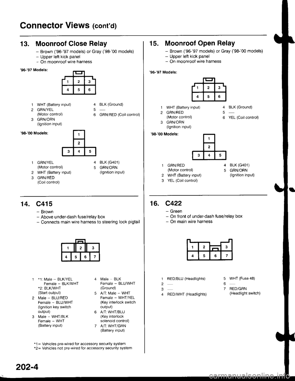
Connector Views (cont'd)
13. Moonroof Close Relay
'96-�97 Models:
1 WHT (Battery input)
2 GRN//EL
{Motor conirol)
3 GRN/ORN(lgnition lnput)
- Brown ('96-'97 models) or Gray ('98-'00 models)- Upper left kick panel- On moonroof wire harness
5
6
BLK (Ground)
GBN/RED (Coilconkol)
'98r00 Models:
GRN/YEL(Motor control)
WHT (Battery input)
GRN/RED(Coil control)
4 BLK (G401)
5 GRN/ORN(lgnition input)2
3
15. Moonroof Open Relay
- Brown ('96-'97 models) or Gray ('98-'00 models)- Upper left kick panel- On moonrool wire harness
'96.�97 Models:
1 WHT (Battery input)
2 GRN/FED(lvlotor control)
3 GRN/ORN(lgnition input)
'98r00 Modelsi
BLK (Ground)
YEL (Coil conkol)
5
6
GBN/RED(lvlotor control)
WHT (Battery input)
YEL (Coil control)
4 BLK (G401)
5 GRN/ORN(lgnition input)2
3
,1^t
6
14. C415
- Brown- Above underdash fuse/relay box- Connects main wire harness to steering lock pigtail
* 1: [,4ale BLKryELFemale - BLKMHT*2: BLK,/WHT(Start oulput)
l\.4ale - BLU/REDFemale - BLUruVHT(lgnilion key switchoutpur)
N4ale - WHT/BLKFemale - WHT(Battery input)
l\,4ale BLKFemale - BLU^VHT(Ground)
Ani Male - WHTFemale - WHT /EL
(Key interlock switchourpur)
A/T:WHT/BLU(Key interlocksolenold control)
A"rT: WHT/GRN(Battery inpul)
*1= Vehicles pre-wired for accessory security system*2= Vehicles not pre wired for accessory security system
202-4
16. C422
- Green- On tront ol under-dash tuse/relay box- On main wire harness
7
l
2
3
4
5
6
7
FED/BLU (Headlights)
REDAVHT (Headlights)
WHT (Fuse 48)
BED/GRN(Headlight switch)