light HONDA CIVIC 2000 6.G Workshop Manual
[x] Cancel search | Manufacturer: HONDA, Model Year: 2000, Model line: CIVIC, Model: HONDA CIVIC 2000 6.GPages: 2189, PDF Size: 69.39 MB
Page 1719 of 2189
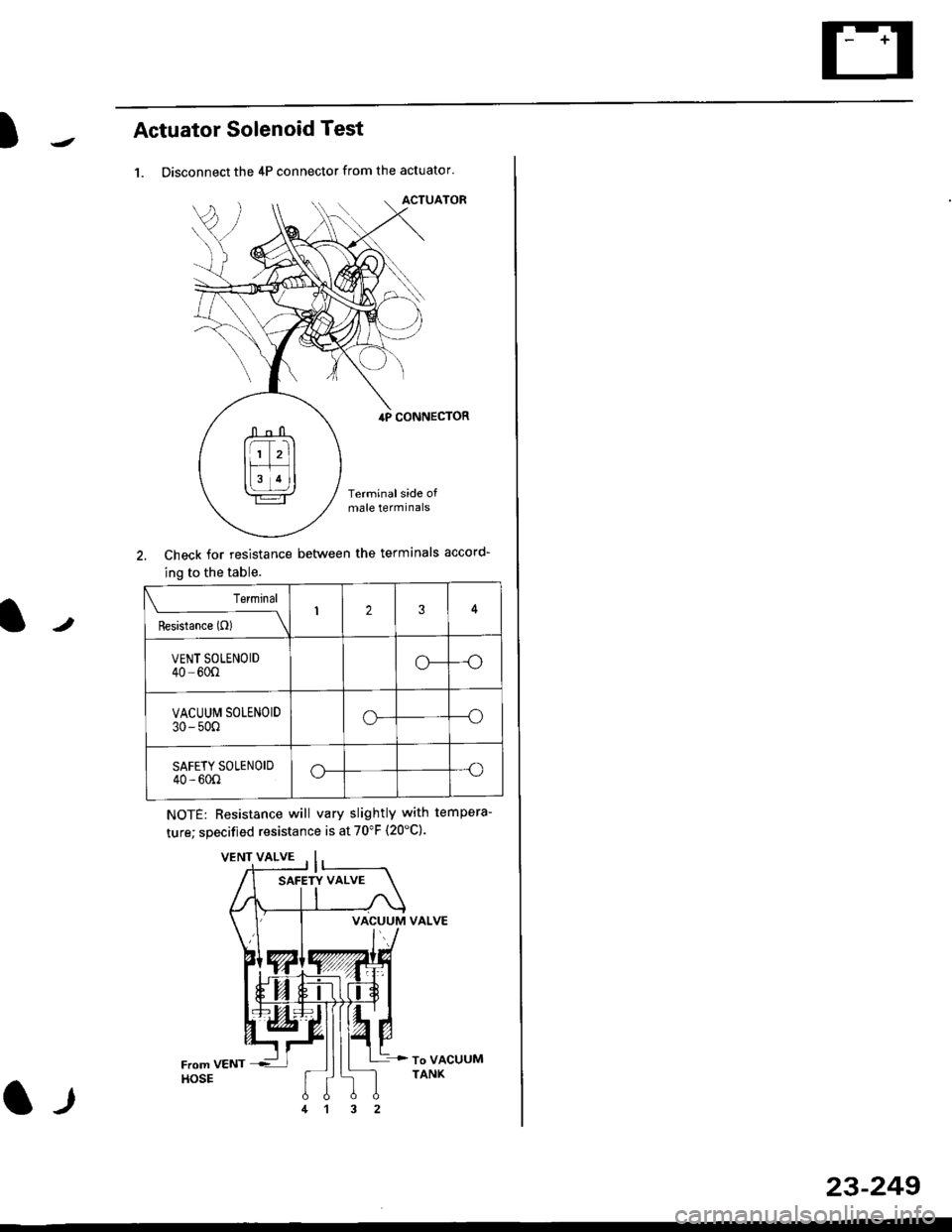
)Actuator Solenoid Test
1. Disconnect the 4P connector from the actuator'
ACTUATOR
2. Check for resistance between the terminals accord-
ing to the table.
NOTE: Resistance will vary slightly with tempera-
ture; sDecified resistance is at 70"F (20'C).
SAFETY VALVE
VACUUMVALVE
J
From VENTHOSE
+ To VACUUM
Terminalside otmale terminals
Terminal
Resistance (O) \
234
VENT SOLENOID40 600o---o
VACUUM SOLENOID30- 500G---o
SAFETY SOLENOID40- 600o---o
l)
TANK
23-249
Page 1721 of 2189
Power Door Locks
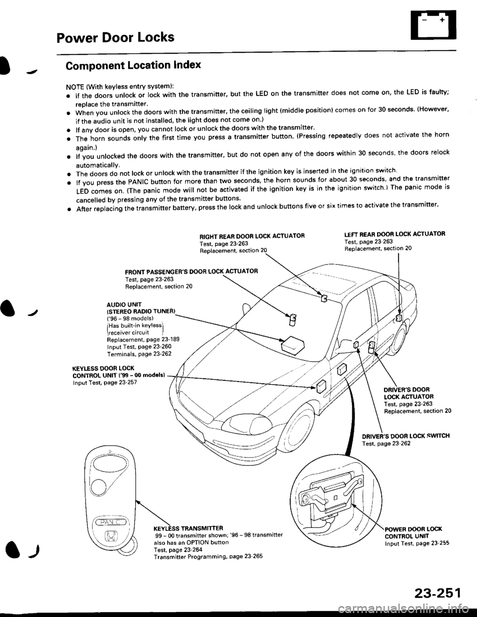
Component Location Index
NOTE (With keyless entry systeml:
. It the doors unlock or lock with the transmitter, but the LED on the transmitter does not come on, the LED is faulty;
replace the transmitter'
. when vou unlock the doors with the transmitter, the ceiling light (middle position) comes on for 30 seconds. (However,
if the audio unit is not installed, the light does not come on )
. lf any door is open, you cannot lock or unlockthe doors with the transmitter'
. The horn sounds only the first time you press a transmitter button. (Pressing repeatedly does not activate the horn
again.)
o lf vou unlocked the doors with the transmitter, but do not open any of the doors within 30 seconds, the doors relock
automatically.
. The doors do not lock or unlock with the transmitter if the ignition key is inserted in the ignition switch
. lf you press the PANIC button for more than two seconds, the horn sounds for about 30 seconds, and the transm'fer
LED comes on. (The panic mode will not be activated iJ the ignition key is in the ignition switch ) The panic mode is
cancelled by pressing any of the transmitter buttons'
o After replacing the transmitter battery, press the lock and unlock buttons five or six times to activate the transmitter'
Replacement, section 20
FRONT PASSENGER'S DOOR LOCK ACTUATOR
RIGHT REAR DOOR LOCK ACTUATOR
Test, page 23-263
I.IFT REAR DOOR LOCK ACTUATOR
Test, page 23 263Replacement, section 20
LOCK ACTUATORTest, page 23-263Replacement, section 20
ORIVER'S DOOR LOCK SWITCH
Test, page 23'262
DOOR L@XCONTROL UN]TInput Test, page 23 255
23-251
Test, page 23-263Replacement, section 20
AUDIO UNIT(STER€O RADIO TUNER)
{'96 - 98 models)
lHas built-in keylessl
eceiver circuit IReplacement, page 23-189
Input Test, page 23-260
Terminals, page 23-262
KEYLESS DOOR LOCKCONTROL UNIT l'99 - 00 modelsl
Input Test, Page 23-257
l-l
TRANSMITTER99 - 0O transmitter shown;'96 -98 transmifter
also has an OPTION buttonTest, page 23-264Transmitter Programming, page 23_265
Qi,,a/
/----
L(ru
i'.-8,-'l
/'-'6
Page 1723 of 2189
)1
ITRUNKLIGHT
GRNiRED LT GRN/ NED
AA
Ii,llh* T#,
I lctoseo : Door open ) | (ctoseo . ooo, open
I Looen Doot dosed J I Loner :ooot closet
tl
ll-: -l
@
wl
r,*1.,. ,,Tr,
,
I llltii irl:rx l5|i;e''lv
|
'r-1--
I
IBLU/YEL
TGFIVRED
I *r.oro,ro
I coNTRor uNrr
fF7IY \IT \
|L
AA
Y6su-' YFHrLo,,"
liili.}
',"**, r
liHi:
e*,**, r
ll-;
KEYLESS RECEIVER CIRCUIT(ln lhe audio unrl)
l"'l"l''o'*i*"
| |-"'i:"j^,"
l'*tectotroI coNTROL UNIT
I ,Y,
IBLU/RED
A
Y.r'ro,u
l:!llT -, ..".-
I
l-ope1 (ey temoved
BLK
I
);
G402
23-253
Page 1731 of 2189
I
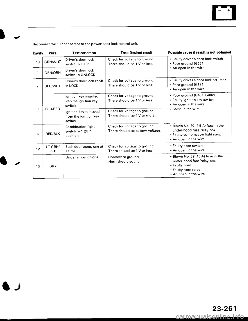
Reconnect the 18P connector to the power door lock control unit
Cavitv Wire Test condition Tost: Desired resultPossible cause it r€sult is not obisinod
23-261
l-l
'10GRNA/VHTDriver's door lock
switch in LOCK
Check for voltage to groundl
There should be 1 V or less.
. Faulty driver's door lock switch. Poor grou nd (G551)
. An open in the wire
9GRN/ORNDriver's door lock
swirch in UNLOCK
2BLU,ryVHT
Driver's door lock knob
in LOCK
Check for voltage to ground:
There should be 1 V or less.
Faulty driver's door lock actuator
Poor ground {G551)
An open in the wire
3BLU/RED
lgnition key inserted
into the ignition key
swttcn
Check for voltage to groundl
There should be 1 V or less
Check for voltage to ground:
There should be 4 V or more
Ch."k f"r ".lt"r" t. g|'"r^d
There should be banery vollage
Poor ground (G401, G402)
Faulty ignition key switch
An open in the wire
Shon in the wire
A o*n tto gO ,i5 A' fr." in tf'"
Lrnder hood fuse/relay box
Faulty combination light switch
An open in the wire
lgnition key removed
from the ignition key
swtrcn
RED/BLK
Combination light
switch in " :m: "
position
LT GRN/
RED
Each door open, one at
a trme
Check tor voltage to ground:
There should be 1 V or less.
Faulty door swilch
An open in the wire
GRY
U nder all conditionsBlown No. 52 (15 Al fuse in the
under hood fuse/relay box
Faulty horn
Fau lty horn relay
An open in the wire
Connect to ground:
Horn should sound.
Page 1733 of 2189
)
l-l
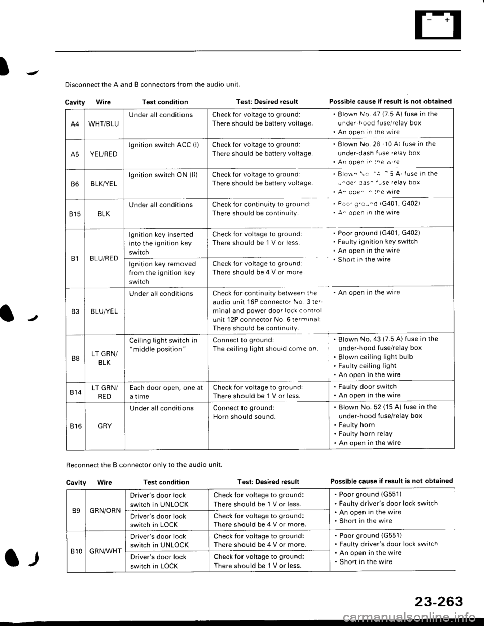
Disconnect the A and B connectors from the audio unit.
Cavity WireTest conditionTest: Desired resultPossible cause if result is not obtained
Reconnect the B connector only to the audio unit.
Cavity WireTest conditionTest: Desired resultPossible cause iI result is not obtained
B9GRN/ORN
Driver's door lock
switch in UNLOCK
Check for voltage to ground:
There should be 1 V or less.
. Poor ground 1G551). Faulty driver's door lock switch. An open in the wire. Short in the wireDriver's door lock
switch in LOCK
Check for voltage to grou nd:
There should be 4 V or more.
810G R NAr'r'HT
Driver's door lock
switch in UNLOCK
Check for voltage to ground:
There should be 4 V or more.
. Poor ground (G551)
. Faulty driver's door lock switch. An open in the wire. Shon in the wireDriver's door lock
switch in LOCK
Check lor voltage to ground:
There should be I V or less.
23-263
A4WHT/BLU
LJnder all conditionsCheck {or voltage to ground:
There should be battery voltage.
. Blown No. 47 (7.5 A) tuse in the
under hood fuse,i relay box. An open n the w re
A5YEL/RED
lg nition swirch ACC (l)Check for voltage to ground:
There should be battery voltage.
Blown No. 28 , I0 A) f use in the
under dash fuse.elay box
An open " :ne n re
Check for voltage to ground:
There should be battery voltage.
Check for continuity to groundr
There should be continuity.
B o$. \. '.1 - 5 A' iuse n the
,,^oe' aas_'-se relay box
A_ ooe^ ' :ne wrre
Pc.' E'o--d rG401, G402)
A- ooen n lhe wire
B6B LK,/YE L
lgnition switch ON0l)
8158LK
Under all conditions
B1BLU/RED
lgnition key inserted
into the ignition key
swrtch
Check for voltage to ground:
There should be 1 V or less
Check for voltage to ground:
There should be 4 V or more
Poor ground (G401, G402)
Faulty ignition key switch
An open in the wire
Short in the wire
An open in the wireCheck for continuity berwee. lFe
audio unit 16P connector l-o 3ler-
minal and power door lock control
unit 12P connector No. 6 lermrnal:
There should be continu ty
lgnition key removed
from the ig nition key
swtlcn
B3B LUlt/E L
U nderall conditions
B8LT GRN/
BLK
Ceiling light switch in"middle position"
Connect to ground:
The ceiling lighr shouldcome on.
Blown No.43 (7.5 A) fuse in the
under-hood Iuse/relay box
Blown ceiling light bulb
Fau lty ceiling light
An open in the wire
814LT GRN/
RED
Each door open, one at
a time
Check tor voltage to ground:
There should be'l V or less.
. Faulty door switch. An open in the wire
Br6GRY
U nderall conditionsConnect to groundl
Horn should sound.
. Blown No. 52 ('15 A) fuse in the
under-hood fuse/relay box
. Fau lty horn. Faulty horn relay. An open in the wire
Page 1734 of 2189
Power Door Locks
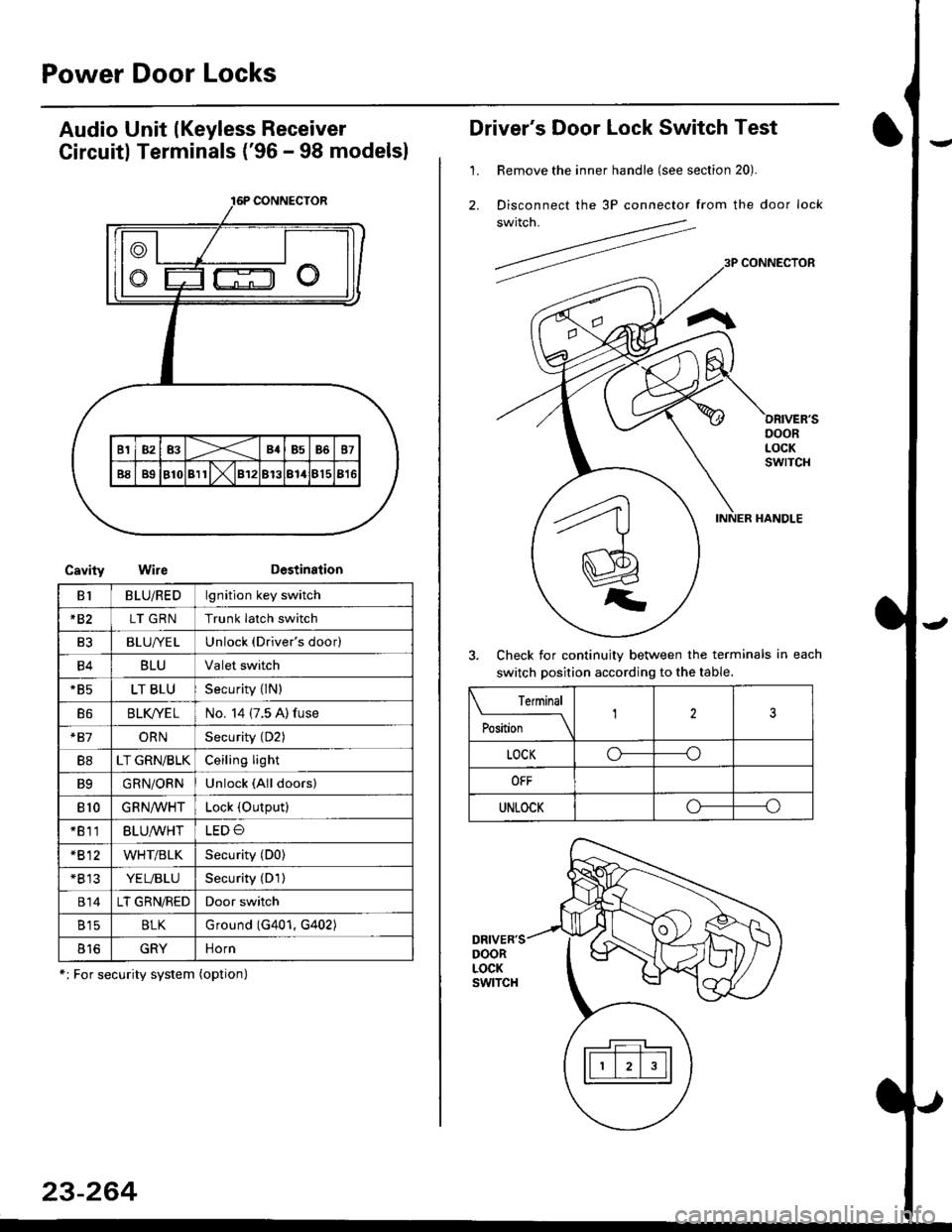
Audio Unit lKeyless Receiver
Circuitl Terminals ('96 - 98 modelsl
CavityWireDestination
16P CONNECTOR
B1BLU/REDlgnition key switch
*82LT GRNTrunk latch switch
Ft2BLU/YELUnlock (Driver's door)
B4BLUValet switch
*85LT BLUSecurity {lN)
B6BLK/YE LNo. 14 (7.5 A) fuse
*81ORNSecurity (D2)
B8LT GRN/BLKCeiling light
B9GRN/ORNUnlock (All doors)
810GRNA/VHTLock (OutPutl
*811BLU/WHTLED O
*812WHT/BLKSecurity (D0)
+B 13YEL/BLUSecurity (D'l )
814LT GRN/REDDoor switch
B15BLKG round (G401, G402)
o toGRYnorn
*: For security system (option)
23-264
Driver's Door Lock Switch Test
1. Remove the inner handle (see section 20).
2. Disconnect the 3P connector from the door lock
switch.
Check for continuity between the terminals in each
switch position according to the table.
DRIVER'SDOORLOCKswtTcH
Terminal
Position123
LOCKo-----o
OFF
UNLOCKo----o
Page 1736 of 2189
Power Door Locks
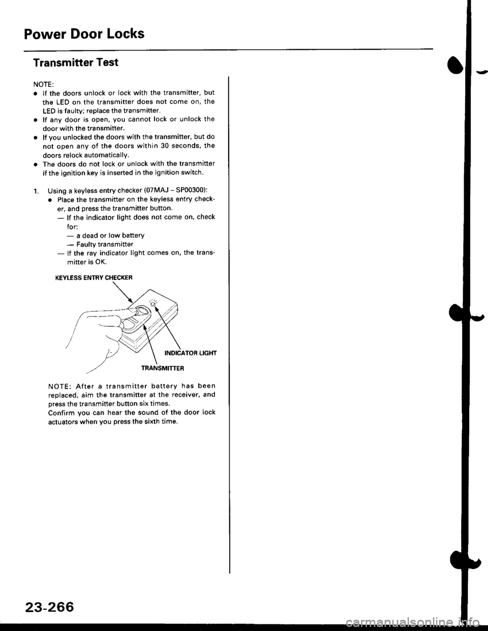
Transmitter Test
NOTE:
. lf the doors unlock or lock with the transmitter, but
the LED on the transmitter does not come on, the
LED is faulty; replace the transmitter.
. lf any door is open, you cannot lock or unlock the
door with the transmitter.
. lf you unlocked the doors with thetransmitter, but do
not open any of the doors within 30 seconds, the
doors relock automatically.
. The doors do not lock or unlock with the transmitter
if the ignition key is inserted in the ignition switch.
1. Using a keyless entry checker (07MAJ - SP003001:
. Place the transmitter on the keyless entry check-
er, and press the transmitter button.
- lf the indicator light does not come on, check
for:- a dead or low batterv- Faulty transmitter- lf the ray indicator light comes on, the trans-
mitter is OK.
KEYLESS ENTRY CHECKER
INDICATOR LIGHT
TRANSMITTER
NOTE: After a transmitter battery has been
replaced, aim the transmitter at the receiver, and
press the transmitter button six times,
Confirm you can hear the sound of the door lock
actuators when vou press the si)dh time.
23-266
Page 1739 of 2189
)
Troubleshooting
Sef f -dia gnostic Proctdurcs ............. 2+13
Reading the DTC .............................. 2+13
Erasing the DTC Mcnrory ................ 24-15
Troubleshooting h.ttnitt.nt
Failures ..............24-15
SRS U n it ldcntificrtion .................... 24- 1 6
Diagnostic Troublc Code (DTC)
Chart - '96 - 97 Models..."'."....... 24-17
Diagnostic Trouble Code (DTCI
Chart - '$ - 00 Models '.........""' 24'19
SRS lndicaror Light Wire
connections ...'.,24-25
Ff owcharts ........,,,,.24-26
Airbag
Repfacemant ...'.'...24-67
Disposaf .................24'70
Cable Reel
Repfacement .........24'72
SRS Unh
Repfacement ..'......24'76
l-l
-+
sRs
Supplemental Restraint System (SRSI
Speciaf Tools ... ...........24'2
Component/Wirin g Locations
fndex ................ ......24-3
Description ................ 24-5
Circuit Diagram ......." 24'6
Precautions/Procedures
Generaf Precautions ...............,,,,,,,.. 24-7
Airbag Handling and Storage .........24-7
SRS Unit Precautions ...................... 24-8
Inspection After Deployment ........' 24-8
Wiring Precautions ................... ....... 24'9
Backprobing Spring-loaded Lock
Connectors .......,24-9
Spring-loaded Lock Connectol ....,,. 24-10
Spring-loaded Lock Connector with
Built-in Short Contact ................. 24-10
Disconnecting the Airbag
Connector(sl .....' 24'11
Steering-related Precautions ...,.,.,,. 24'12
Page 1741 of 2189
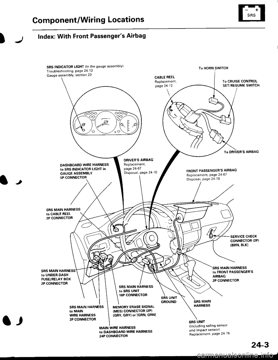
Component/Wiring Locations
)
Index: With Front Passenger's Airbag
SRS INDICATOR LIGHT (ln the gauge assemblvl
Troubleshooting, Page 24 13
Gauge assembly, section 23CABLE REEL
Replacemenlpage 2!-t 2
To HORN SWITCH
SRS UNIT(lncluding safing sensor
and imPact sensorl
Replacement Page 24 76
To DRIVER'S AIRBAG
DASHBOARD WIRE HARNESS
to SRS INDICATOB LIGHT in
GAUGE ASSEMBLY5P CONNECTOB
DBIVER'S AIRBAG
Beplacement,page 24-61Disposal, page 24 70FRONT PASSENGER'S AIBBAG
Replacement, Page 24_67
Disposal, Page 24 70
t
SRS MAIN HARNESSto CABI-E RE€L2P CONNECTOR
SRS MAIN
SERVICE CHECKCONNECTOR {2PI
IBRN, BLK]
to UNOER-OASHFUSE/RELAY BOX2P CONNECTOR
SRS MAIN HARNESSto FRONT PASSENGER'SAIRBAG2P CONNECTOB
SRS MAIN HARNESSto SRS UNITr8P CONNECTOR
SBS MAIN HARNESSto MAINWIRE HARNESS3P CONNECTOR
MEMORY ERASE SIGNAL(MES) CONNECTOR I2P)
[GRY, GRYI or IGRN. GRNI
MAIN WIRE HARNESSto DASHBOARD WIRE HARNESS
24P CONNECTOR
2+3
t,
Page 1742 of 2189
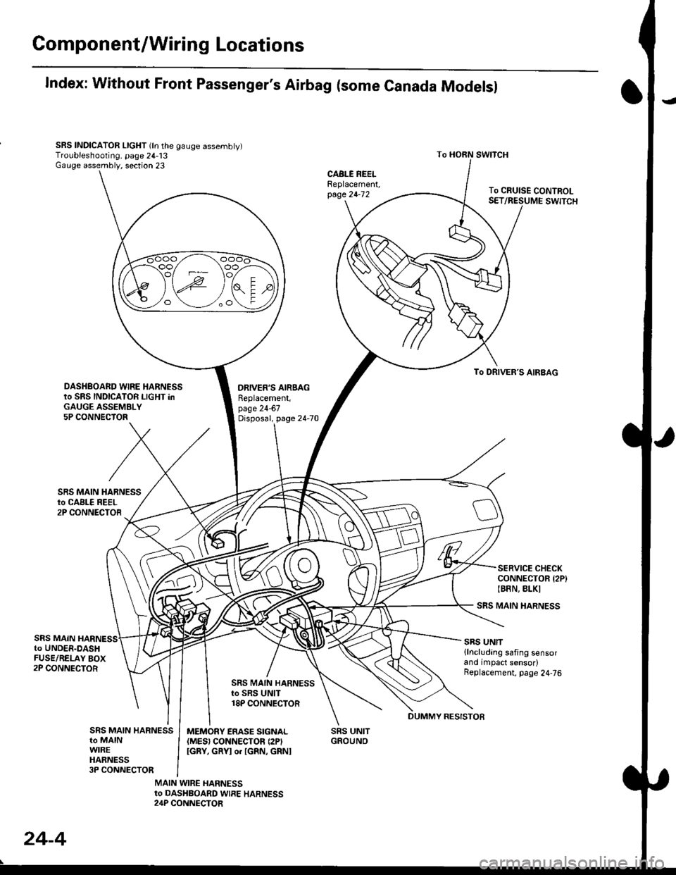
Gomponent/Wiring Locations
Index: Without Front Passenger's Airbag (some Canada Modelsl
SRS INDICATOR LIGHT (ln the gauge assembly)Troubleshooting, page 24-13Gauge assembly, section 23
DRIVER'S AIRSAGReplacement,page 24-67Disposal, page 24-70
SRS UNITGROUNO
To HORN SWITCH
SRS MAIN HARNESS
SRS UNIT{lncluding safing sensorand impact sensor)Replacement. page 24,76
To CRUISE CONTROLSET/RESUME SWITCH
oo/ \oo
To DRIVER,S AIRBAG
DASHBOARD WIRE HARNESSto SRS INDICATOR LIGHT inGAUGE ASSEMBLY5P CONNECTOR
SERVICE CHECKCONNECTOR {2P}IB8N, BLKI
SRS MAINto UNDER-DASHFUSE/RELAY BOX2P CONNECTOR
SRS MAIN HARNESSto SRS UNIT18P CONNECTOR
SRS MAIN HARNESSto MAINWIREHARNESS3P CONNECTOR
MEMORY ERASE SIGNAL(MES) CONNECTON (2P'
IGRY, GRYI o. IGRN, GRNI
MAIN WIRE HARNESSto DASHBOARD WIRE HARNESS24P CONNECTOR
24-4
DUMMY RESISTOB