ect HONDA CIVIC 2000 6.G Workshop Manual
[x] Cancel search | Manufacturer: HONDA, Model Year: 2000, Model line: CIVIC, Model: HONDA CIVIC 2000 6.GPages: 2189, PDF Size: 69.39 MB
Page 635 of 2189
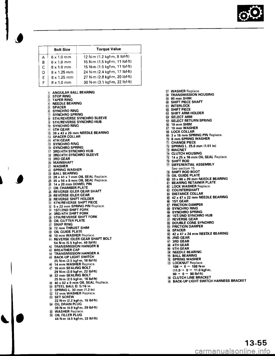
Bolt SizeTorque Value
cn
E
F
6x1.0mm
6x1.0mm
8 x 1.0 mm
8 x '1.25 mm
8 x 1.25 mm
8 x 1,0 mm
12 N.m (1.2 kgnm, 8 lbf'ft)
15 N.m (1.5 kgf'm, 11 lbf ft)
15 N.m (l.5 kgf.m, 11 lbift)
24 N'm (2.4 kgim, 17 lbift)
27 N.m (2.8 kgf.m,20 lbf'ft)
30 N.m (3.1 ksf m. 22 lbift)
5i WASHER Replace.6 TRANSMrssioN HouslNG!9 80 mm SHIM@ SHIFT PIECE SHAFT(6' INTERLOCK@ sHrFr PECE6} SHIFT ARM HOLDER@ seucr nnrvtI9 SELECT RETURN SPRING
@ 10 mm SHIM6, 10 mm WASHER@ LOCK COLLARi6sl 3 x l5 mm SPRING PIN Replace.t0 8 mm SPRING WASHERA) CHANGE PIECEll SPRING L.25.6 mm (1.01 in)'' MAGNET?4) CLUTCH HOUSINGta. 14 x 25 x 16 mm OIL SEAL Replace.A sHrFT BooO D|FFERENT|aL ASSEMBLYSee section 15iIO SHIFT ROD BOOT6 OIL GUIDE PLATE@ 33 x 60 x 20 mm NEEDLE BEASINGO BEARING RETAINER PLATElD LocK WASHER Replace..0 couNTERSHAFIA DISTANCE COLLAR6 & x 4I x 22 mm NEEDLE BEARING6. 1sr GEAR@ FRICTION DAMPERO SYNCHRO RING.d SYNCHRO SPRING@ 1ST/2ND SYNCHRO HUB..9i. REVERSE GEARC) DOUBLE CONE SYNCHROO FRICTION DAMPERS SPACER6 T2 x TI x 24 mm NEEDLE BEARING(!' 2ND GEAR61 3RD GEARiD 4TH GEAR@ 5TH GEAR(O NEEDLE BEARING(10 BALL BEARING@ SPRING WASHERf,o LoCKNUT Replace.108 - 0- 108 N'm111.0- 0* 11.0 kgf m,80* 0- 80lbI.ft)IO CLUTCH LINE BRACKET.d BACK.UP LTGHT SWITCH HARNESS BRACKET
:!, ANGULAR BALL BEABING:2, STOP RING:3] TAPER RING..-I NEEOLE BEARINGl!-- SPACERO SYNCHRO RING? SYNCHRO SPRINGE 5TH/REVERSE SYNCHRO SLEEVE...] sTH/REVERSE SYNCHRO HUB
O SYNCHBO EING.11-r sTH GEAR1A 38 x 43 x 26 mm NEEDLE BEARINGI13) SPACER COLLAR[!] /ITH GEAR.T5) SYNCHRO RING
O SYNCHRO SPRING17 3RD/4TH SYNCHRO HUB
O 3RD/4TH sYNcHRo SLEEVE
ii9 38D GEAR8I MAINSHAFT2i WASHERA SPRING WASH€R?I BALL BEARING.a4, 28 x 41 x 7 mm OIL SEAL Replace..2i 35 x 56 x 8 mm OIL SEAL Replace.t-t 14 x 20 mm DowEL PIN
.'] OIL CHAMBER PLATE
O REVERSE IDLER GEAR SHAFT.iI.., REVERSE IDLER GEAR'd REVERSE SHIFI HOLDERait srH/REVERSE sHIFT PIECE'34 5 x 22 mm SPRING PIN Replace.3' 1ST/2ND SHIFT FORK,34' 3RD/4TH SHIFT FORKi9t) srH/nevense sstrr ronx33 OIL GUTTER PLATE!' SNAP RING3d 72 mm THRUST SHIM
@ OIL GUIDE PLATE4t 10 mm WASHER Replaceti REVERSE TDLER GEAR SHAFT BoLT54 N.m {5.5 kgf m, 40lbIft)4N TBANSMISSION HANGER B43] BREATHER CAPA,J TRANSMISSION HANGER AIT' BACK-UP LIGHT SWITCH
I
25 N.m {2.5 kgl.m, 18lblftl14 mm WASHER RePlaceaO 14 mmtt 16 mm16 mm SEALING BOLT29 N.m (3.0 kgf m,22 lbf ft):4s) 32 mm SEALING BoLT25 N m 12.5 kgl m, 18 lbl'ft)40 x 62 x I mm OIL SEAL ReplaceSTEEL BALL D.5/15 iNSPRING L. 30 mm {1.2 in)12 mm WASHER Replace.SET SCREW22 N.m {2.2 kg{ m, 16 lbl ftlOIL DRAIN PLUG39 N.m {4.0 kgf m, 29lbtftlWASHER Replace.OIL FILLER PLUG4,t N.m {4.5 kgl m, 33 lblftl
.!rl00
@l
13-55
Page 637 of 2189
Reverse Shift Holder,
Reverse ldler Gear
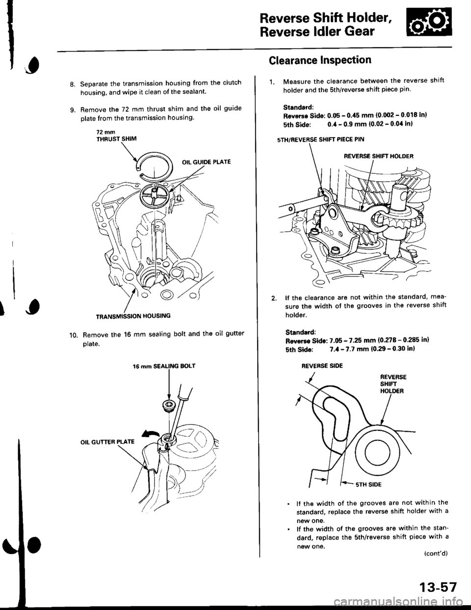
Separate the transmission housing from the clutch
housing, and wipe it clean of the sealant.
Remove the 72 mm thrust shim and the oil guide
plate from the transmission housing
72fifiTHRUST SHIM
TRANSMISSION HOUSING
Remove the 16 mm sealing bolt and the oll gutter
plate.
OIL GUTTER PLATE
fi
1.
Clearance Inspection
Measure the clearance between the reverse shift
holder and the 5th/reverse shift piece pin
Standard:
Revsrs. Sids: 0.05 - 0./t5 mm {0'002 - 0.018 in}
5th Side: 0.4 - 0.9 mm (0.02 - 0.0'l in)
sTH/REVERSE SHIFT PIECE PIN
lf the clearance are not within the standard, mea-
sure the width of the grooves in the reverse shift
holder.
Standard:
Rsvers€ Side: 7.05 - 7.25 mm (0'278 - 0.285 in)
5th Sid6: 7.,1- 7.7 mm (0.29 - 0 30 inl
REVERSE SIDE
lf ths width of the grooves are not within the
standard, replace the reverse shift holder with a
new one.
lf the width of the grooves are within the stan-
dard, replace the sth/reverse shift piece with a
new one {cont'd)
13-57
Page 638 of 2189
Reverse Shift Holder, Reverse ldler Gear
Clearance Inspection (cont'dl
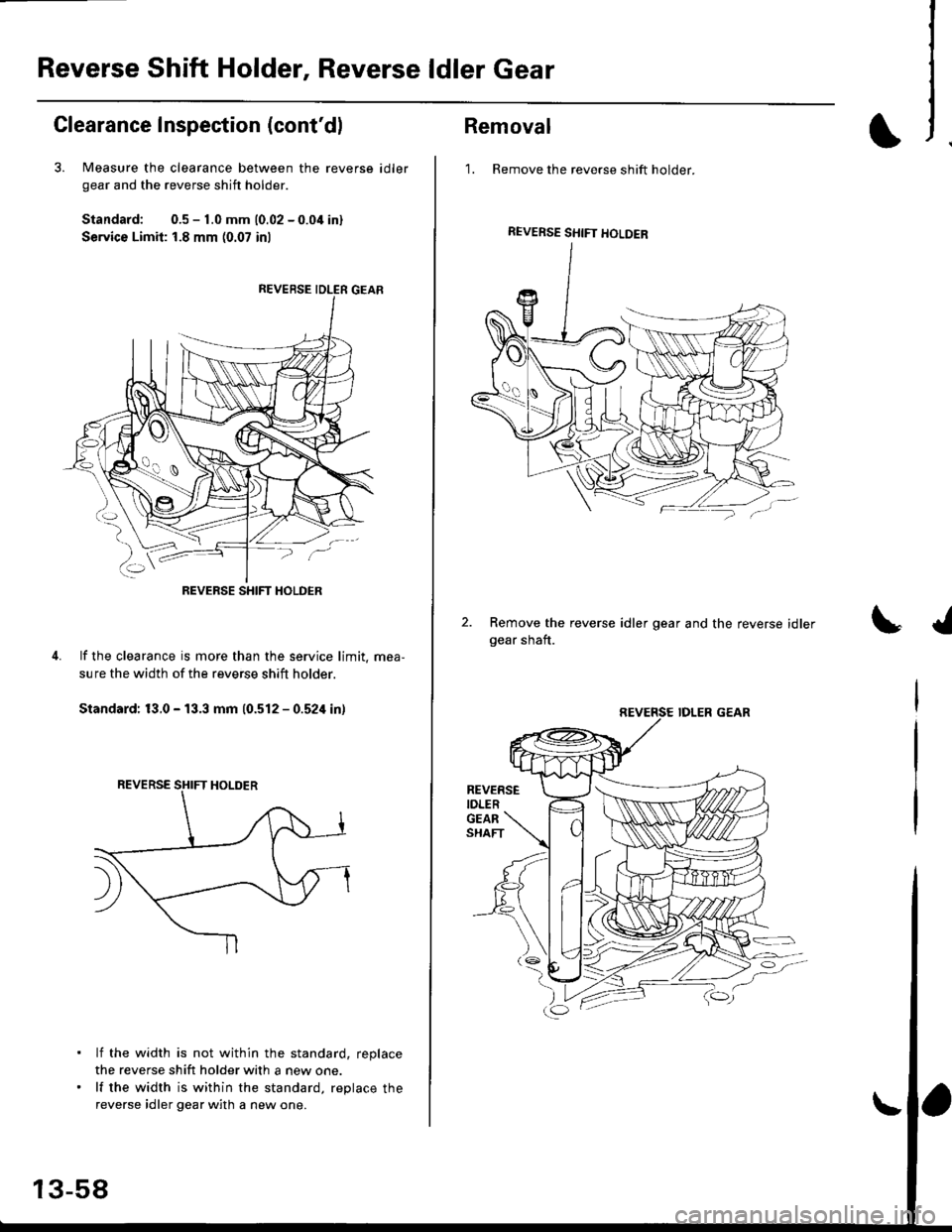
3. Measure the clearance between the reverse
gear and the reverse shift holder.
Standard: 0.5 - 1.0 mm 10.02 - 0.04 inl
Service Limit: 1.8 mm (0.07 inl
id ler
lf the clearance is more than the service limit. mea,
sure the width of the reverse shift holder.
Standard: 13.0 - 13.3 mm (0.512 - 0.524 in)
lf the width is not within the standard, replace
the reverse shift holder with a new one.
lf the width is within the standard, replace the
reverse idler gear with a new one.
REVERSE SHIFT HOLDER
13-58
Removal
1. Remove the reverse shift holder.
Remove the reverse idler gear and the reverse idlergear shaft.
REVERSE SHIFT HOLDEB
REVERSEIDLER
Page 639 of 2189
Change Holder AssemblY
,Glearance InsPection
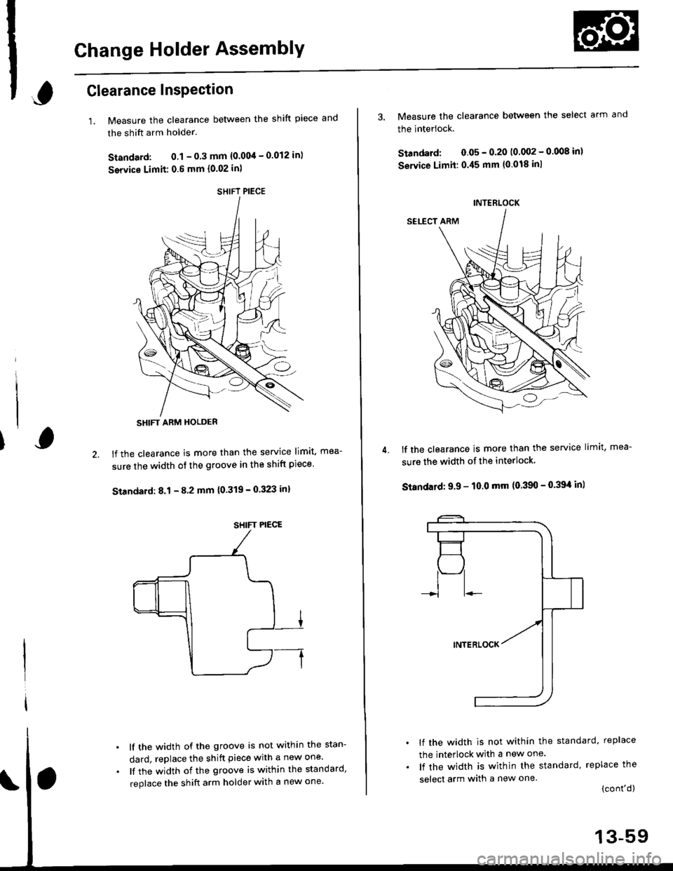
1.Measure the clearance between the shift piece and
the shift arm holder.
Standard: 0.1 - 0.3 mm {0.004 - 0.012 in)
service Limit: 0.6 mm {0.02 in)
lf the clearance is more than the service limit, mea-
sure the width of the groove in the shift piece'
Standard: 8.1 - 8 2 mm {0'319 - 0.323 in}
lf the width of the groove is not within the stan-
dard, replace the shift piece with a new one'
lf the width of the groove is within the standard,
replace the shift arm holder with a new one'
SHIFT PIECE
SHIFT ARM HOLDER
SHIFT PIECE
4.
3. Measure the clearance between the select arm and
the interlock.
Standard: 0.05 - 0.20 10 002 - 0.008 inl
Service Limit:0.45 mm (0.018 inl
lf the clearance is more than the service limit, mea-
sure the width of the interlock.
Standatd: 9.9 - 10.0 mm (0.390 - 0.39't in)
lf the width is not within the standard, replace
the interlock with a new one.
lf the width is within the standard, replace the
select arm with a new one.(cont'd)
INTERLOCK
13-59
Page 640 of 2189
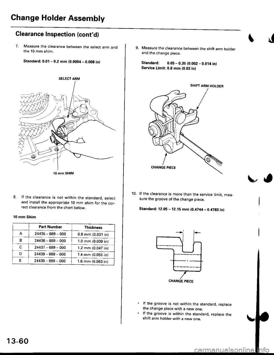
Change Holder Assembly
Clearance Inspection (cont'd)
7. Measure the clearance between the select arm andthe 10 mm shim.
Standard: 0.01 - 0.2 mm (0.0004 - 0.008 in)
lf the clearance is not within the standard, selectand install the appropriate l0 mm shim for the cor-rect clearance from the chart below.
mm Shim
8.
SELECT ARM
l0 mm SHIM
Part NumberThickness
24435-689-0000.8 mm (0.031 in)
B24436-589-0001.0 mm (0.039 in)
c24437-689-0001.2 mm (0.047 in)
D24438-689-0001.4 mm (0.055 in)
E24439-689-0001.6 mm {0.063 in)
13-60
I
9. Measure the clearance between the shift arm holderand the change piece.
Standard; 0.05 - 0.35 (0.fi)2 - 0.014 inlService Limit: 0.8 mm (0.03 in)
lf the clearance is more than the service limit. mea_sure the groove of the change piece.
Standard: 12.05 - 12.15 mm {0.i[7it4 - 0.47txt inl
lf the groove is not within the standard, replacethe change piece with a new one.lf the groove is within the standard, replace theshift arm holder with a new one.
vo
SHIFT ARM HOLOER
CHANGE PIECE
Page 641 of 2189
UO
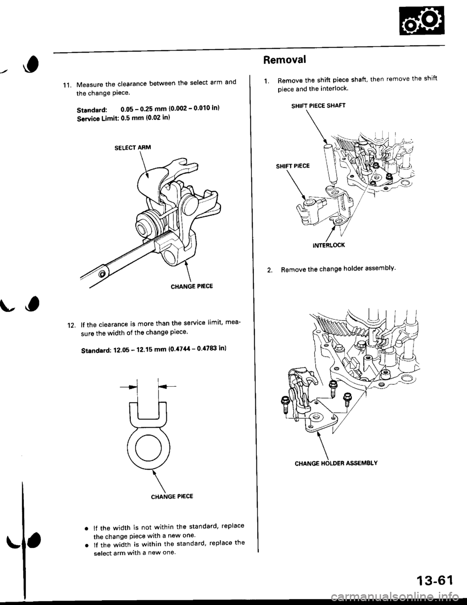
11. Measure the clearance between the select arm and
the change Piece.
Standard: 0.05 - O'25 mm 10'002 - 0'010 in)
Servica Limii: 0.5 mm {0.02 in)
lf the clearance is more than the service limit, mea-
sure the width of the change Plece.
Standard: 12.05 - 12.15 mm {0.47'|{ - 0 47tI| inl
CHANGE PIECE
lf the width is not within the standard, replace
the change Piece with a new one'
lf the width is within the standard, replace the
select arm with a new one.
't2.
a
a
SELECT ARM
Removal
1. Bemove the shift piece shaft. then remove the shift
piece and the interlock.
SHIFT PIECE SHAFT
INTERLOCK
2. Remove the change holder assembly'
13-61
Page 642 of 2189
![HONDA CIVIC 2000 6.G Workshop Manual Change Holder Assembly
Disassembly/Reassembly
I Pio to """sembring, crean aI the pans in sorvent, dry them and appry lubricant to any contact surfaces.
l0 mm SH|M
I
,o mm wAsHEF
t/
@@d.
r]7| 3 x 1 HONDA CIVIC 2000 6.G Workshop Manual Change Holder Assembly
Disassembly/Reassembly
I Pio to """sembring, crean aI the pans in sorvent, dry them and appry lubricant to any contact surfaces.
l0 mm SH|M
I
,o mm wAsHEF
t/
@@d.
r]7| 3 x 1](/img/13/6068/w960_6068-641.png)
Change Holder Assembly
Disassembly/Reassembly
I P'io' to '"""sembring, crean aI the pans in sorvent, dry them and appry lubricant to any contact surfaces.
l0 mm SH|M
I
,o mm wAsHEF
t/
@@d.
r]7| 3 x 16 mm SpRtNGI Replace.
R€TURN SPRING
SELECT ARM
13-62
Page 646 of 2189
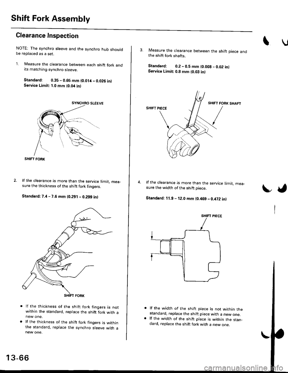
Shift Fork Assembly
Clearance Inspection
NOTE: The synchro sleeve and the synchro hub shouldbe replaced as a set.
1. Measure the clearance between each shift fork andits matching synchro sleeve.
Standard: 0.35 - 0.65 mm {O.Olit - 0.026 inlService Limit: 1.0 mm t0.04 inl
SHIFT FOBK
lf the clearance is more than the service limit. mea_sure the thickness of the shitt fork finoers.
Standard: 7.4 - 7.6 mm (0.291 - 0.299 in)
lf the thickness of the shift fork frngers rs notwithin the standard, replace the shift fork with anew one.
lf the thickness of the shift fork fingers is withinthe standard, replace the synchro sleeve with a
13-66
3. Measure the clearance between the shift piece andthe shift fork shafts.
Standard: 0.2 - 0.5 mm (0.008 - 0.02 inlService Limit: 0.8 mm {0.03 in)
lf the clearance is more than the service limit. mea-sure the width of the shift Diece.
Standard: 11.9 - 12.0 mm (0.469 - 0.it72 in)
lf the width of the shift piece is not within thestandard, replace the shift piece with a new one.lf the width of the shift piece is within the stan_dard, replace the shift fork with a new one.
t,
SHIFT PIECE
Page 647 of 2189
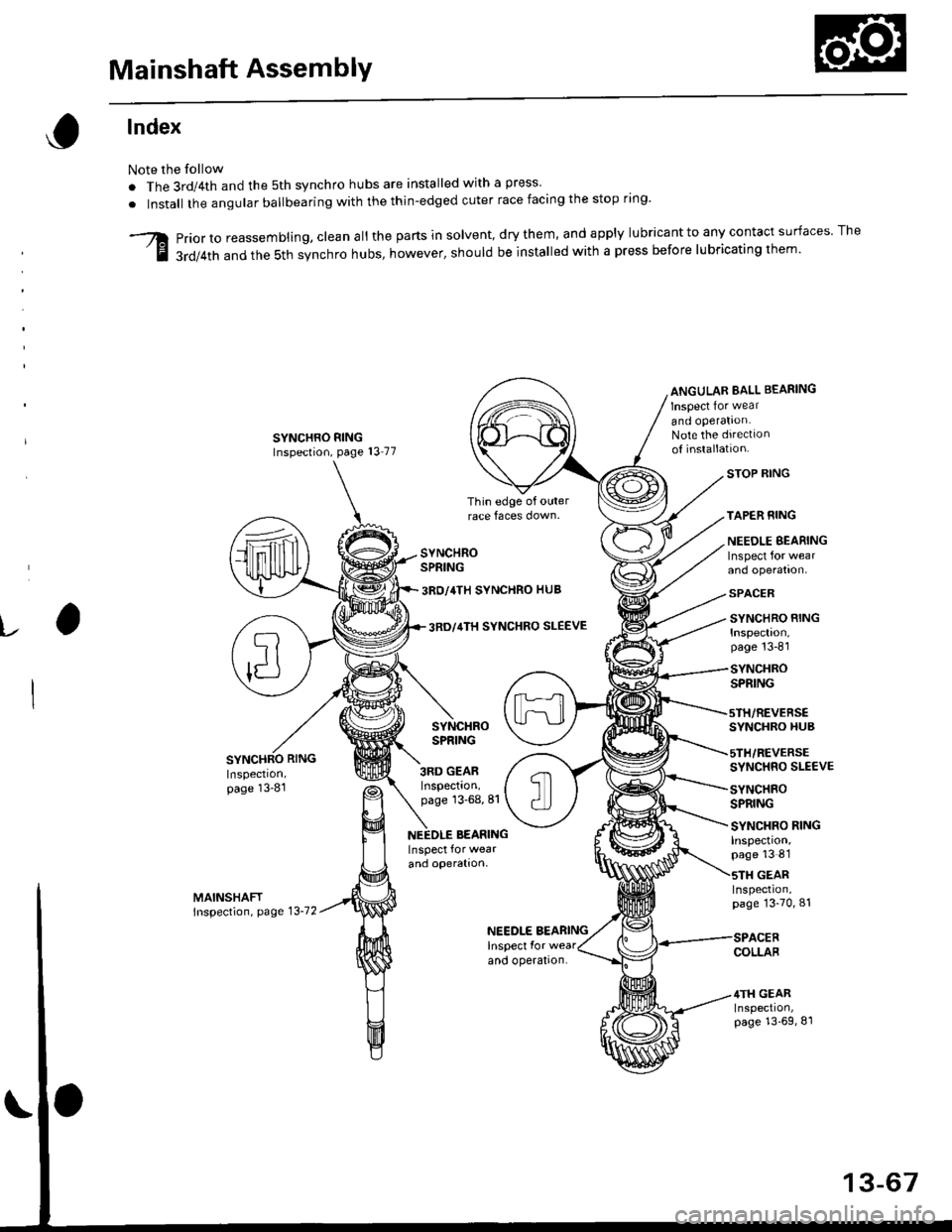
Mainshaft AssemblY
lndex
Note the follow
. The 3rd/4th and the 5th synchro hubs are installed with a press
. Install the angular ballbearing with the thin-edged cuter race facing the stop rrng'
Priorto reassembling. clean all the parts in solvent,drythem, and apply lu brica nt to any contact su rfaces The
3rd/4th and the sth synchro hubs, however, should be installed with a press before lubricating them'
ANGULAR BALL BEARING
Inspect lor wear
and operation.Note the drrectlonoI installatton.
v
SYNCHROSPRING
3RO/4TH SYNCHRO HUB
3RD GEARInspection,page 13-68,81
3RO/4TH SYNCHRO SLEEVE
SYNCHROSPRING
STOP RING
TAPER RING
NEEOLE EEARINGInspect for wearand operation.
SPACER
SYNCHRO RINGInspection.page 13-81
SYNCHROSPRING
SYNCHRO HUB
5TH/REVERSESYNCHRO SLE€VE
SYNCHEOSPRING
Inspection,page 13-81
NEEDLE BEARING
and operation.
SYNCHRO RINGInspection,page 13 8'1
GEARInspeclron,page 13-70,81
NEEDLE BEARINGInspect Ior wear
and operation.COLLAB
4TH GEARInspection,page 13'69,81
13-67
Page 648 of 2189
Mainshaft Assembly
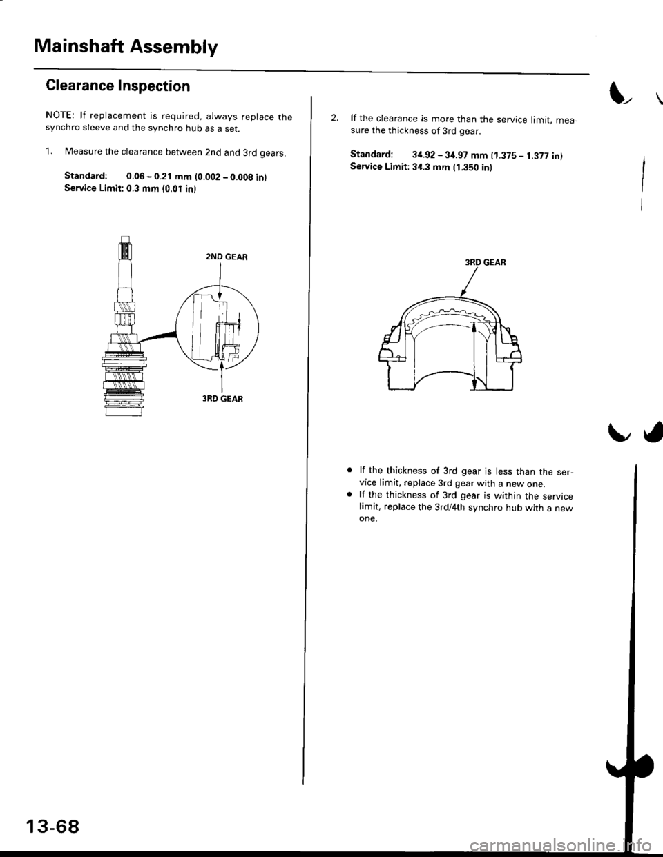
Clearance Inspection
NOTE: lf replacement is required, always reDlace thesynchro sleeve and the synchro hub as a set.
1. Measure the clearance between 2nd and 3rd oears,
Standard: 0.06 - 0.21 mm (0.002 - 0.008 inlService Limit: 0.3 mm (0.01 inl
2. lf the clearance is more than the service limit, mea-sure the thickness of 3rd gear.
Standard: 34.92 - 3it.97 mm t1.375 - 1.377 intService Limit: 3,1.3 mm (1.350 inl
lf the thickness of 3rd gear is less than the ser-vice limit. replace 3rd gear with a new one.lf the thickness of 3rd gear is within the servicelimit, replace the 3rd/4th synchro hub with a newone.
Id