evap HONDA CIVIC 2000 6.G Repair Manual
[x] Cancel search | Manufacturer: HONDA, Model Year: 2000, Model line: CIVIC, Model: HONDA CIVIC 2000 6.GPages: 2189, PDF Size: 69.39 MB
Page 537 of 2189
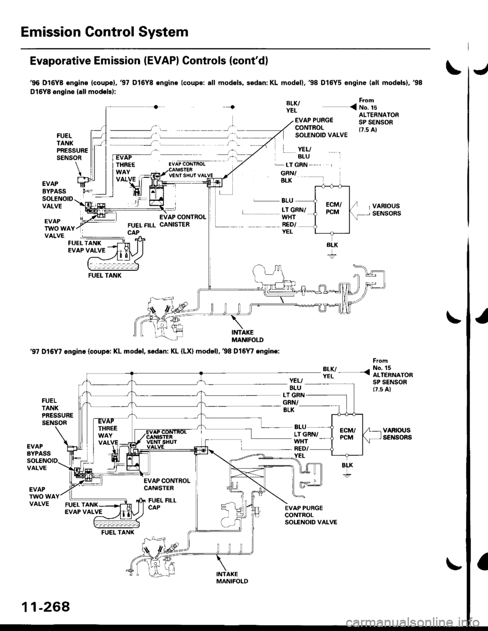
Emission Control System
Evaporative Emission IEVAPI Controls (cont'd)
'96 D16Y8 ongins (coupol.'97 D16Y8 €ngino (coups: all mod€ls, sedan: KL model),'98 D16Y5 engine (all mod6lsl,'98
Dl5YB engine {all modols):
{BLK/YEL
From
< No. 15
FUELTANKPRESSURESENSOR
EVAP PURG€CONTROLSOLENOID VALVE
.� LT GRN
GRN/BLK
ALTERNATORSP SENSOR(7.5 A)
VARIOUSSENSORS
YEL/BLU
V€NT SHUT
EVAPBYPASSSOLENOIDVALVEL BLU
WHTRED/YEL
L __ LT GRN/
EVAPTWO WAYVALVE
INTAKEMANIFOI.I'
'97 D16Y7 engin. (coupa: KL model, sedan: KL {LX) model},38 Dl6
/ engine:
?:y- -<
FromNo. 15ALTERNATORSP SENSOR17.5 A)
FUELTANKPRESSURESENSOR
YEL/BLULT G]GRN/BLK
LT GRN/WHT
BLU
YEL
EVAPBYPASSRED/
VALVE
EVAPTWO WAVALVE
EVAP CONTROLCANISTER
FUEL FILLCAP
BLK
11-268
FUEL TANK
Page 538 of 2189
J
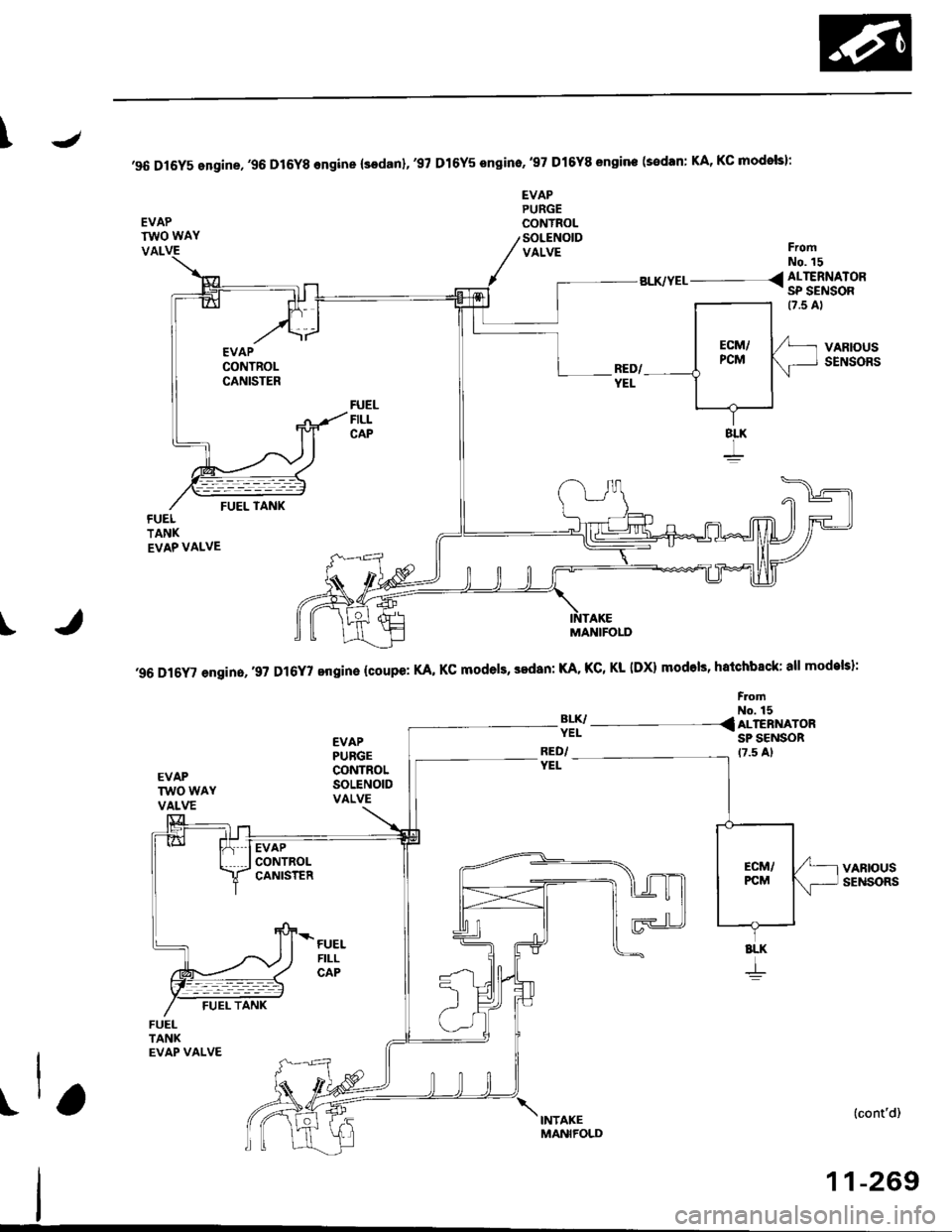
'96 Dl6Y5 engine,'96 D16Y8 engine (sodanl,'97 Dl6Y5 sngino,'97 Dl6Y8 sngine (sedan: KA, KC modols):
EVAPTWO WAY
EVAPPURGECONYROLSOLENOIDVALVEVALFromNo. 15
BLK/YEL__ _ < ALTERNATOR- SP SENSOR
FUELFILLCAP
VARIOUSSENSORS
(cont'd)
11-269
I
'96 D16Y' engin.,.9? D16Y7 engine {coupe: KA, KC models, sedan: KA. KC, Kl- IDX) modols, hatchback: all models}:
FromNo. 15
3lI/- - - -{ ALTERNAT'RSP SENSORRED/YEL
EVAPPUBGECONTROLSOLENOIDVALVE
FUELFILLCAP
8LK
+
t\,"ro*,
MANIFOLD
Page 539 of 2189
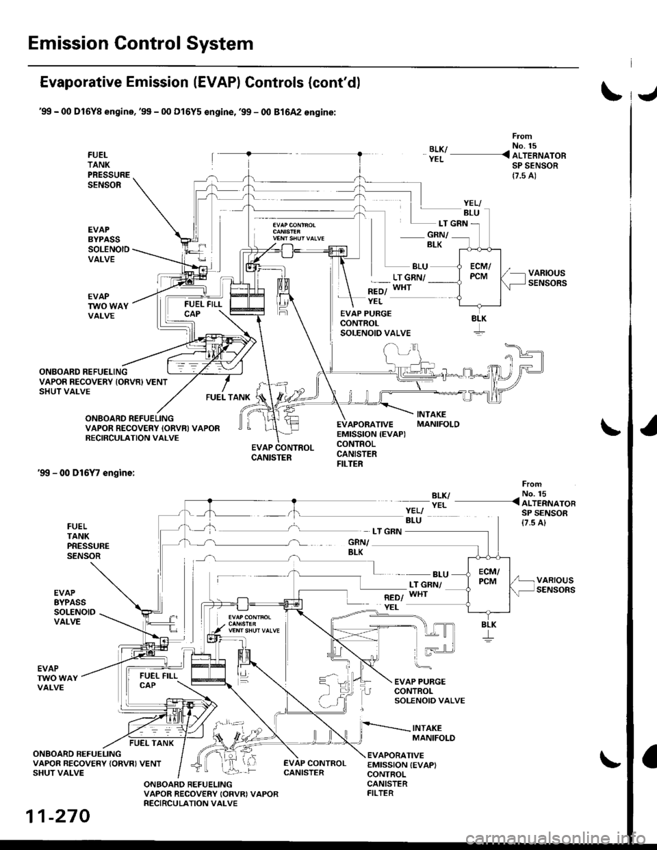
Emission Control System
Evaporative Emission (EVAPI Controls (cont'd)
'99 - 00 Dl6Yg engine,'99 - 00 Dl6Y5 €ngine,'99 - 00 81642 engine:
FUELTANKPRESSURESENSOR
EVAPBYPASSSOLENOIDVALVE
From
BLK/ - No. 15
YEL _ ALTERNATORSP SENSOR
{7.5 A)
- GRN/BLK
BLU
*=ol
LT GRN/WHT
ONBOARD REFUELING
FUEL TANK
EVAP PURGECONTROLSOLENOID VALVE
EVAPORATIVEEMISSION {EVAP)CONTROLCANISTERFILTER
YEL
LT GRN
VAPOR RECOVERY IONVR) VENTSHUT VALVE
ONBOARD REFUELINGVAPOR RECOVERY IORVN} VAPORRECIRCULATION VALVE
'99 - 00 D16Y7 engine:
EVAP CONTROLCANISTER
BLK/YEL
FromNo. 15< ALTERNATORSP SENSOR{7.5 A}FUELTANKPRESSURESENSOR
EVAPEYPASSSOLENOIDVALVE
- BLULT GNN/WHT
EVAP PURGECONTROLSOLENOIO VALVE
INTAKEMANIFOLD
EVAPTWO WAYVALVE
FUEL TANK
ONBOARD REFUELINGVAPOR RECOVERY {ORVRI VENTSHUT VALVE
EVAPORATIVEEMISSION {EVAPICONTROL
EVAP CONTROL
ONBOARD REFUELINGVAPOR RECOVERY IORVRI VAPORRECIRCULATION VALVE
CANISTERFILTER
YELI
8LK
11-270
CANISTER
Page 540 of 2189
\J
\
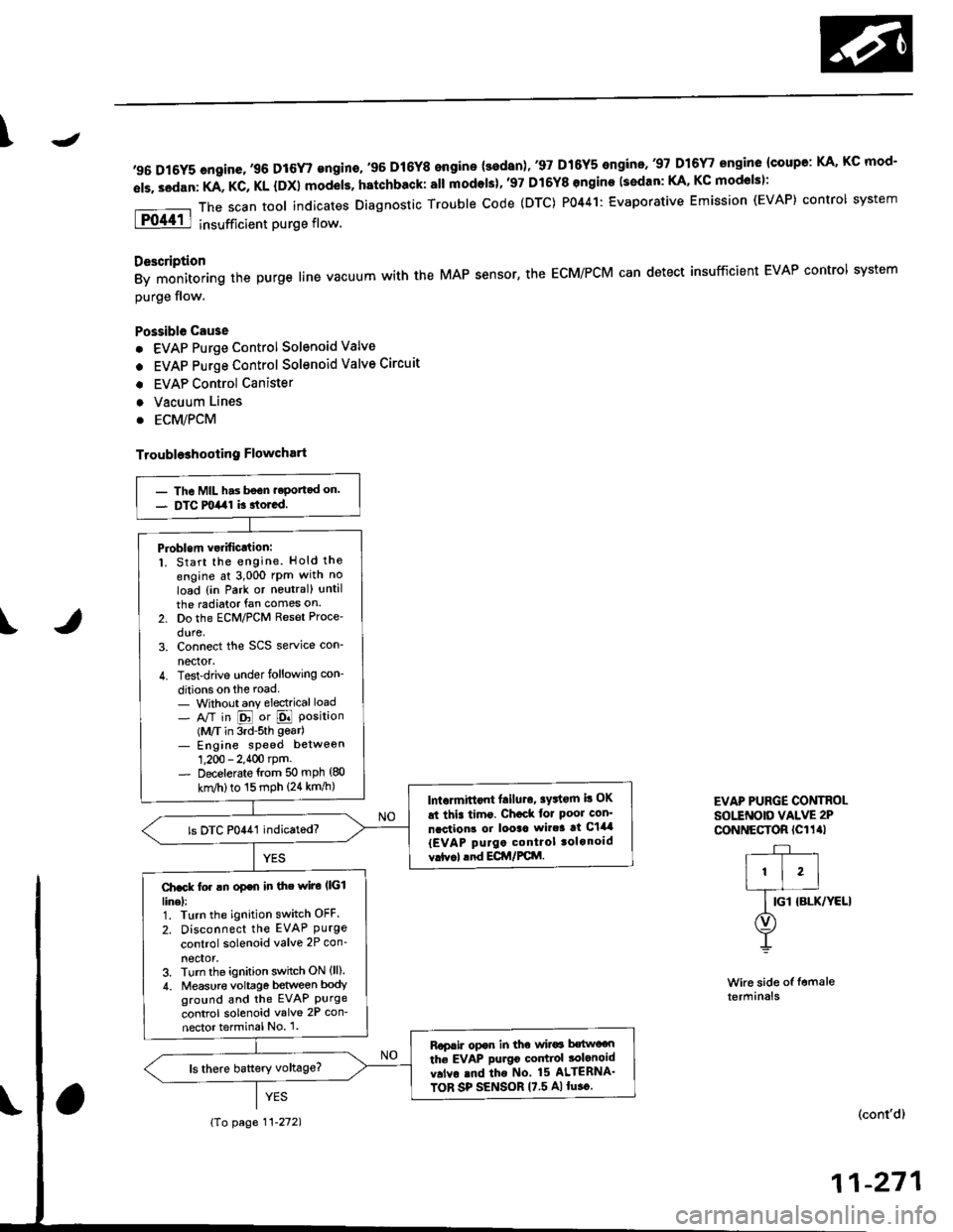
,96 D16Y5 engine,,96 D16r,gngino,,96 Dt6Y8 engine {3edan)' 37 D16Y5 engino..97 D16r, engine {coupe: KA, Kc mod-
els. sedan: KA, KC, KL {DX} models. hatchback: all modols}''97 Dl6Y8 ongine (s€dan: KA' KC mod€lsl:
The scan tool indicates Diagnostic Trouble code (DTC) P0441: Evaporative Emission (EVAP) control system
insufficient purge flow.
Description
By monitoring the purge line vacuum with the MAP sensor, the ECM/PCM can detect insufficient EVAP control system
purge flow.
Possible Cau3e
. EVAP Purge Control Solenoid Valve
. EVAP Purge Control Solenoid Valve Circuit
. EVAP Control Canister
. Vacuum Lines
. ECM/PCM
Troubl93hooting Flowchart
Wire side of femaleterminals
EVAP PURGE CONTROI-sottNotD vALvE 2P
CoNNECTOR (Cl1al
r-+-r
I'l'l
lG-ro.*l'rr"r
O)
Y
(cont'd)
11-271
- The MIL has bsGn.eportad on.- DTC milal k rtored.
Pioblem vsrificJtion:1. Start the engine. Hold the
engine at 3,000 rPm with no
load {in Park or noutral) until
the radiator fan comes on.
2. Do the ECM/PCM Reset Proce'
dure,3. Connect the SCS service con-
nector.4. Test-drive under following con-
ditions on the road- Without any electrical load- A/T in E or E Position(M/T in 3rd-sth gear)- Engine sPeed betweon
1,200 - 2.400 rpm.- Decelerate {rom 50 mph (80
knl/h)to 15 mph (24 km/h)lntormittont lailuro, sFtorn b OK
at thi. timo. Ch€ck tor Poor con'
ncction3 or looac wir.3 at C144
{EVAP purgo control tolonoid
vrtv.l .nd ECir/FCttl.
ls DTC P0441 indicatod?
Ch.ck fo. !n op€n in the wiro l|(illinel:1. Turn the ignition switch OFF.
2. Disconnect the EVAP Purgecontrol solenoid valve 2P con_
neclor,3. Turn the ignition switch ON (ll)
4. Measur€ voltage between bodyground and the EVAP Purgecontrol solenoid valve 2P con-
nector terminal No 1.
Rop.ir opor in tho wir6 b€two€n
the EVAP purgo codtiol tolonoid
v.lvo rnd tho No 15 ALIERNA'
TOR SP SENSOR 17.5 A)lu.o.
{To page 11-272)
Page 541 of 2189
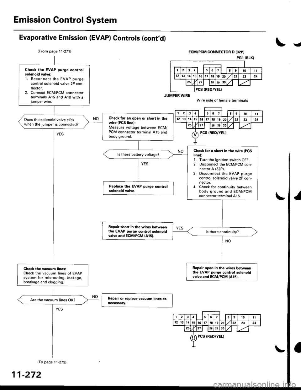
Emission Gontrol System
Evaporative Emission (EVAPI Controls (cont'dl
(From page 11-271)
I
ECM/PCM CONNECTOR D I32P}
PGl IBLKI
Check the EVAP purge controlsolenoid valvei1. Reconnect the EVAP purge
control solenoid valve 2P con-nector.2. Connect ECM/PCM connectorterminals A15 and 410 with a
Check for an open or short in thewire (PCS line):Measure voltage between ECM/PCM connector terminal A15 andbody gro!nd.
Does the solenoid valve clickwhen the jumper is connected?
Che'ck for a short in the wir6 {PCSline):1. Turn the ignition switch OFF.2. Disconnect the ECM/PCM con-nector A (32P).
3. Disconnect the EVAP purgecontrol solenoid valve 2P connector.4. Check lor continuity betweenbody ground and ECM/PCMconnector terminal A15.
Repai. short in the wir6s betwoonthe EVAP purge control solanoidvalve and ECM/rcM lA15l.
R€pair op€n in the wir$ betwo€ntho EVAP purge control solenoidvalve and ECM/rcM lA15l.
Check the vacuum lin€3:Check the vacuum lines ol EVAPsystem for misrouting, leakage,breakage and clogging.
Are the vacuum lines OK?
PCS {REO/YEL)
t389t0'tt
12l3'I'tt5t5'11IE1920232a
?5212A2930
PCS {RED/YEL)
23a67E9t0It
12t3'ta't5l617ta1920222321
2a2728A30
0) Pcs {REo/YELI
-272
Page 542 of 2189
J\
(From page 11-272)D16Y5 engine:
JUMPER WIRE
D16Y7, D16Y8 engine
VACUUMPUMP/GAUGE,
VACUUMPUMP/GAUGE,0 - 30 in.HgAs73x - 0il1 -
xxxxx
0 - 30 in.HgA973X -
otl -
xxxxx
I
EVAP CONTROLCANISTER
ECM/PCM CONNECTOH D I32PI
VACUUM/PBESSUREGAUGE0-4in.Hg07JAZ - 0010008
Wire side otfemale terminals
D16Y7, Dl6Y8 engine:
t
VACUUM/PRESSUREGAUGE0-4 in.Hgo?JAZ - 001fl)OB(cont'd)
11-273
PGl IBLKI
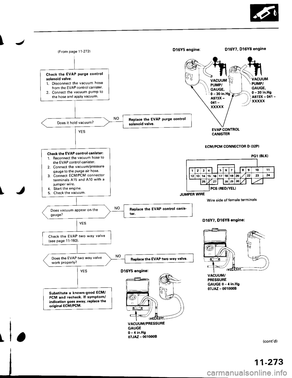
Check lhe EVAP Purge control
solsnoid valve:
1. Disconnect the vacuum hose
from the EVAP controlcanister'
2. Connect the vacuum PumP to
the hose and aPPIY vacuum
Does it hold vacuum?
Check the EVAP control canister:
1. Reconnect the vacuum hose to
the EVAP control canlster.
2. Connect the vacuum/Pressuregaugeto the Purge aar hose
3. Connect ECM/PCM connector
terminals A15 and A10 with a
iumper wire.4. Start the engine5. Check the vacuum
Check the EVAP two way valve(see page 11-193)
Does the EVAP two waY valveReplace the EVAP two wsY valve.
Sub3titute a known-good ECM/
PCM .nd recheck. lt symPtom/
indicrtion go6s away, rePlace the
original ECM/PCM.
D16Y5 sngin€:
Page 543 of 2189
Emission Control System
Evaporative Emission (EVAP) Gontrols (cont'd)
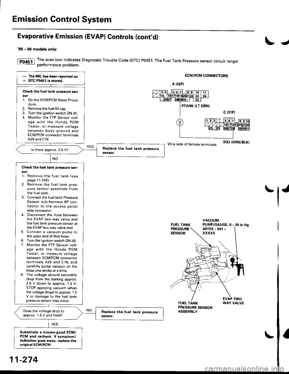
'99 - 0O models only:
The scan tool indicates Diagnostic Trouble Code (DTC) P0451: The Fuel Tank Pressure sensor circuit range/oerformance Droblem.
ECM/PCM CONNECTORS
wire side ot femare terminars sG2 IGRN/BLK)
FUEL TANKPRESSURESENSOR
VACUUMPUMP/GAUGE,0 - 30 in.Hg
FUEL TANKPRESSURE SENSORASSEMBLY
EVAP TWOWAY VALVE
IJ
tl'
Ths MIL has been reDortgd on.DTC m/$1 i3 stored.
Check the tuel tank pros3ure ser|-sor:1. Do the ECM/PCM Reset Proce-dure.2. Remove the tuellill cap.3. Turn the ignition switch ON (ll).4. N4onitor the FTP Sensor volt-age with the Honda PGMTester, or measure voltagebetween body ground andECN4/PCM connector terminalsA29 and C18.
ls there approx. 2.5 V7
Check tho tuel tank pressure !on-soa:1. Remove the fuel tank (seepage 11 2421.2. Remove the fuel tank pres-sure sensor assembly fromthe fueltank.3. Connect the fuel tank PressureSensor sub-harness 6P con-nector to the access panelside connector,4. Disconnect the hose betweenthe EVAP two way valvg andthe fuel tank pressure sensor atthe EVAP two way valve end.5. Connect a vacuum pump tothe open end ofthat hose.6. Turn the ignition switch ON (ll).7. Monitor the FTP Sensor volt,age with the Honda PGMTester, or measure voltagebetween ECM/PCM connectorterminals A29 and C18, andcarefully pump vacuum on thehose one stroke at a time.8. The voltage sho!ld smoothlydrop from the stading approx.2.5 V down to approx. '1.5 V.STOP applying vacuum whenthe voltage drops to approx. 1.5V or damage to the fuel tankpressure sensor may occur.
Does the voltage drop toapprox. 1.5 V and hold?
Sub3titute a known-good ECM/PCM and r6check. It symptom/indicltion 90e3 aw.y, replac\. th€original ECM/PCM.
A (32P)
A973X - 041 -
xxxxx
11-274
Page 545 of 2189
Emission Control System
Evaporative Emission (EVAP) Controls (cont'dl
!
FUEL TANKPRESSURE SENSOR3P CONNECTOR {C7921
PTANK
{LT GRN)
sG2{GRN/BLK)
Wire side of f€mal€ terminals
{From page 11-275)
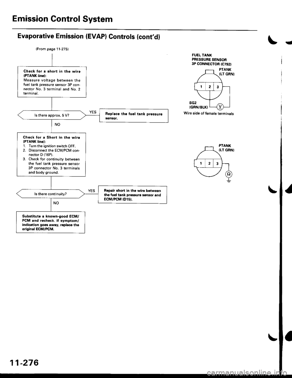
Check to. ! short in the wiroIPTANK linol:Measure voltage between thefirel tank pressure sensor 3P con-nector No. 3 terminal and No. 2terminal,
ls there approx.5 V?
Check fo. a Short in the wireIPTANK IinoI:1. Turn the ignition switch OFF.2. Disconnect the ECM/PCM con,nector D 116P).3. Check for continuity betweenthe fuel tank pressure sensor3P connector No.3 terminalsand body ground.
Repair thort in thc wire betweantho fuel iank pre$uro 3€naor andECM/FCM tDl5t.
ls there continuity?
Substitute ! known-good ECM/PCM and recheck. lf .ymptom/indication go6s awry, repleco th6origin.l ECM/PCM.
PTANK{LT GRNI
-276
Page 547 of 2189
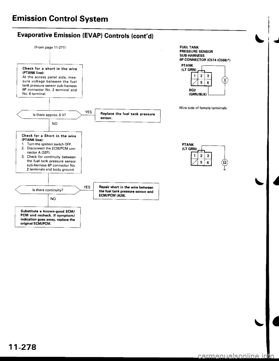
Emission Control System
Evaporative Emission (EVAPI Controls {cont,dlJ
FUEL TANKPRESSURE SENSORSU8-HABNESS6P CONNECTOR 1C574 tC568)rt
PTANK
{LT GRN}
PTANK
ILT GRN}
Wire side of female terminals
(From page 11-277)
Check for a short in the wire{PTANK line):At the access panel side, measure voltage between the fueltank pressure sensor sub-harness6P connector No. 2 terminal andNo. 6 terminal.
ls there approx. 5 V?
Chock lor a Short in the wi.e(PTANK line):1. Turn the ignition switch OFF.2. Disconnect the ECM/PCM con-nector A (32P).
3. Check for continuity betweenthe fuel tank pressure sensorsub-harness 6P connector No.2 terminals and body ground.
Repair short in the wi.e betwsenthe luel tank pressure sensor andECM/PCM {A291.
Subsiitute a known-good ECM/PCM and rechock. lf symptom/indication goes away, replac€ theoriginal ECM/PCM.
11-278
Page 549 of 2189
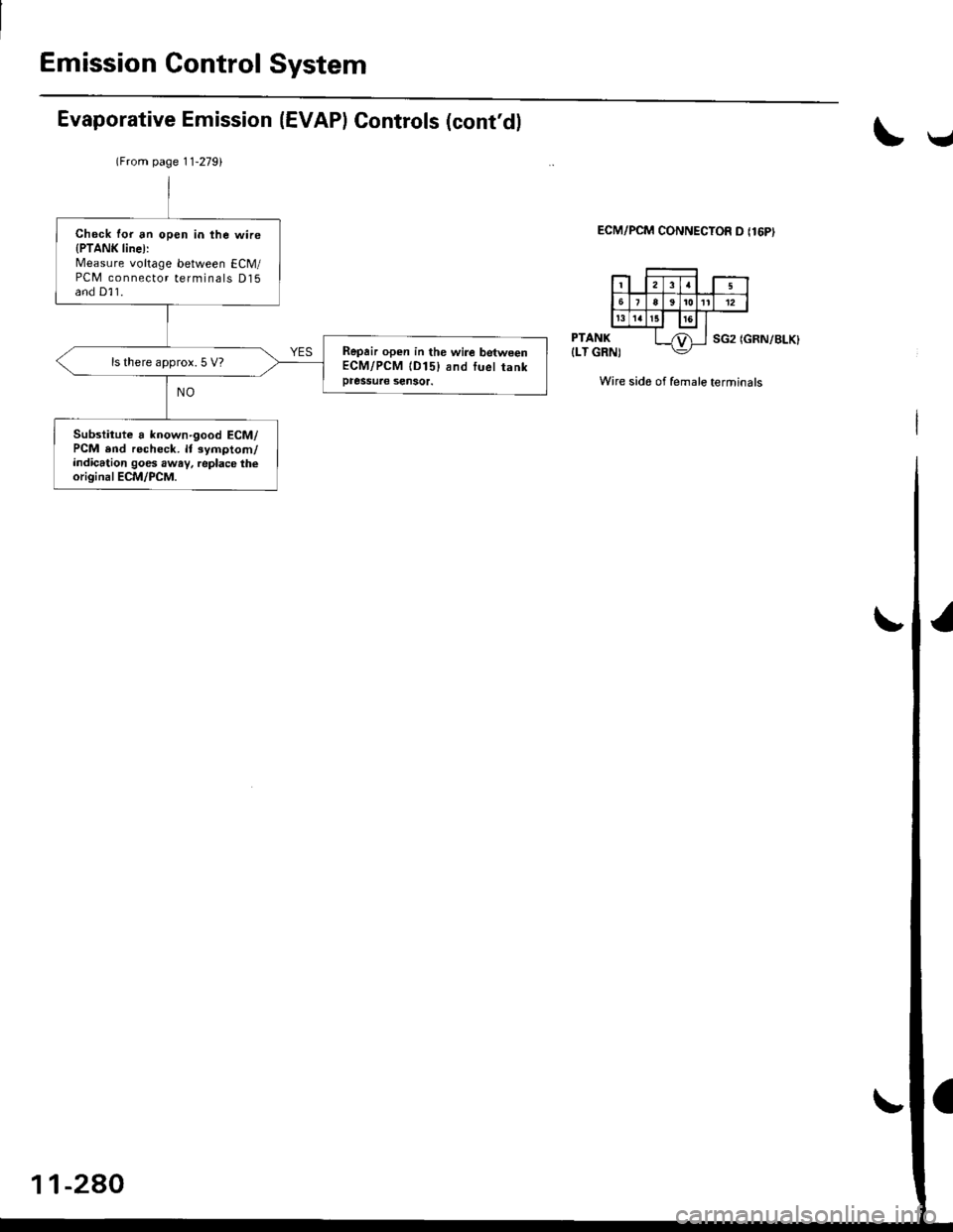
Emission Control System
Evaporative Emission (EVAPI Controls (cont'dl
\v
ECM/PCM CONNECTOR D {16PI
PTANK
{LT GRN)SG2 (GRN/BLK}
Wire side of female terminals
lFrom page 11-2791
Check for an open in the wire{PTANK line):Measure voltage between ECM/PCM connector terminals D15and D]1.
Repair open in the wire betweenECM/PCM lD15) and luel tankpressuae sensor.
ls there approx. 5 V?
Substitute a known'good ECM/PCM end recheck. lt symptom/indication goes awav, replace theoriginal ECM/PCM.
-2AO