evap HONDA CIVIC 2000 6.G Service Manual
[x] Cancel search | Manufacturer: HONDA, Model Year: 2000, Model line: CIVIC, Model: HONDA CIVIC 2000 6.GPages: 2189, PDF Size: 69.39 MB
Page 374 of 2189
3.
5.
6.
1.
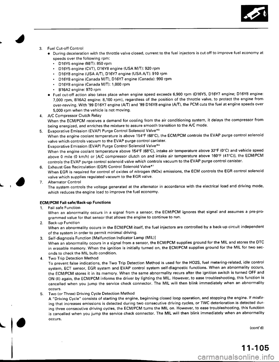
Fuel Cut-off Control
. During deceleration with the throttle valve closed, current to the fuel injectors is cut off to improve fuel economy at
speeds over the following rpm:. D16Y5 engine (M/T):850 rpm. D]6Y5 engine (CVT), D'16Y8 engine (USA M/T): 920 rpm
. Dl6Y8 engine (USA A,/I), D16Y7 engine (USA A,/T);910 rpm
. D16Y8 engine (Canada M/T), D16Y7 engine (canada): 990 rpm
' D16Y8 engine (Canada M/T): 1,000 rpm
. 816A2 engine: 970 rpm
. Fuel cut-off action also takes place when engine speed exceeds 6,900 rpm (D16Y5, D16Y7 engine; D'16Y8 engine:
7,000 rpm. 816A2 engine: 8.100 rpm), regardless of the position of the throttle valve, to protect the engine from
over-rewing. With '99 Dl6Y7 engine (A,/T) and '99 D16Y8 engine (A./T), the PCM cuts the fuel at engine speeds over
5,000 rpm when the vehicle is not moving.
IVC Compressor Clutch Relay
When the ECM/PCM receives a demand for cooling from the air conditioning system, it delays the compressor from
being energized, and enriches the mixture to assure smooth transition to the A,/C mode
Evaporative Emission (EVAP) Purge Control Solenoid Valve*'
When the engine coolant temperature is above 154'F (68'C). the ECM/PCM controls the EVAP purge control solenoid
valve which controls vacuum to the EVAP purge control canister.
Evaporative Emission (EVAP) Purge Control Solenoid Valve*a
When the engine coolant temperature above 154"F (68"C), intake air temperature above 32"F (0'C) and vehicle speed
above 0 mile (0 km/h) or [Ay'C compressor clutch on and intake air temperature above 160"F (41'C)], the ECM/PCM
controls the EVAP purge control solenoid valve which controls vacuum to the EVAP purge control canister.
Exhaust Gas Recirculation (EGR) Control Solenoid Valve*?
When EGR is required for control of oxides of nitrogen (NOx) emissions. the ECM controls the EGR control solenoid
valve which supplies regulated vacuum to the EGR valve
Alternator Control
The system controls the voltage generated at the alternator in accordance with the electrical load and driving mode,
which reduces the engine load to improve the fuel economy.
ECM/PCM Fail-safe/Back-up Functions
1. Fail safe Function
When an abnormality occurs in a signal from a sensor, the ECM/PCM ignores that signal and assumes a pre-pro-
grammed value for that sensor that allows the engine to continue to run.
2. Back-uD Function
When an abnormality occurs in the ECM/PCM itself, the fuel injectors are controlled by a back-up circuit independent
of the system in order to permit minimal driving.
3. Self diagnosis Function lMalfunction Indicator Lamp (MlL)l
When an abnormality occurs in a signal from a sensor, the ECM/PCM supplies ground for the lvllL and stores the DTC
in erasable memory. When the ignition is initially turned on, the ECM/PCM supplies ground for the MIL for two sec-
onds to check the MIL bulb condition.
4. Two Trip Detection Method
To prevent false indications, the Two Trip Detection Method is used for the HO2S, fuel metering-related. idle control
system, ECT sensor, EGR system and EVAP control system self-diagnostic functions. When an abnormality occurs,
the ECM/PCM stores it in its memory. When the same abnormality recurs after the ignition switch is turned OFF and
ON 0l) again, the ECM/PCM informs the driver by lighting the MlL. However, to ease troubleshooting, this function is
cancelled when you jump the service check connector. The MIL will then blink immediately when an abnormality
occurs,
5. Two (or Three) Driving Cycle Detection Method
A "Driving Cycle" consists ot starting the engine. beginning closed loop operation, and stopping the engine. lf misfir-
ing that increases emissions is detected during two consecutive driving cycles, or TWC deterioration is detected dur-
ing three consecutive driving cycles, the ECM/PCM turns the MIL on. However, to ease troubleshooting, this function
is cancelled when you jump the service check connector. The MIL will then blink immediately when an abnormality
occurs.
(cont'd)
1 1-1 05
.1.
Page 433 of 2189
PGM-FI System
Fuel Supply System
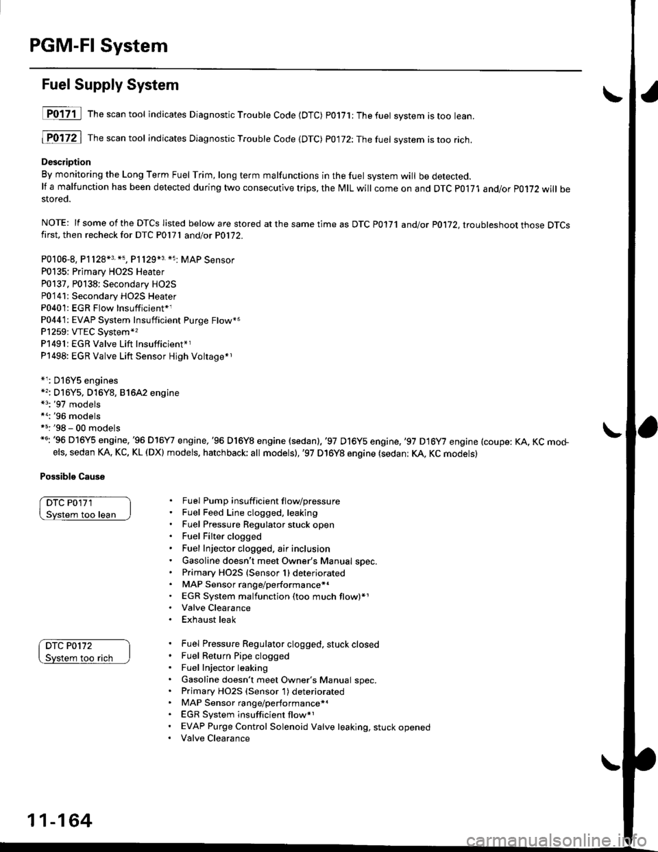
D017-il Th""""ntool indicates Diagnostic Troubte Code {DTC) p0171;Thefuet system istoo lean.
1P0172 | fne scan tool indicates Dlagnostic Trouble Code (DTC) P0172:Thefuel system istoo rich.
Description
By monitoring the Long Term Fuel Trim, long term malfunctions in the fuel system will be detected.lf a malfunction has been detected during two consecutive trips, the MIL will come on and DTC P0171 and/or P0172 will bestored.
NOTE: lf some of the DTCS listed below are stored at the same time as DTC P0171 andlot P0172, ltouhleshoot those DTCSfirst. then recheck for DTC P0l7l andlot P0172.
P0106-8, P1128*3. *5, P1129*3 *5 MAP Sensor
P0135; Primary HO2S Heater
P0137. P0138: Secondary HO2S
P0'141: Secondary HO2S Heater
P0401: EGR Flow Insufficient*1
P0441: EVAP System Insufficient Purge Flow*6
P1259: VTEC System*,
P1491:EGR Valve Lift Insufficient*r
P1498: EGR Valve Lift Sensor Hjgh Voltage*r
*r: D16Y5 engines*'�: Dl6Y5, D16Y8, 81642 engine*3: '97 models*a:'96 modelsf 5: '98 - 00 models*6: '96 D16Y5 engine,'96 D16Y7 engine,'96 D16Y8 engine (sedan),'97 D16y5 engine,,97 D16y7 engine (coupe: KA, KC mo+els, sedan KA. KC, KL (DX) models. hatchback; all models),'97 D16Y8 engine (sedan: KA, KC models)
Possible Cause
DTC P0'171
loo lean
DTC P0172
too rach
Fuel Pump insuff icient f lovpressure
Fuel Feed Line clogged, leaking
Fuel Pressure Regulator stuck open
Fuel Filter clogged
Fuel Injector clogged, air inclusion
Gasoline doesn't meet Owner's Manual spec.
Primary HO2S (Sensor 1) deteriorated
MAP Sensor range/performance*.
EGR System malfunction (too much flow)*1
Valve Clearance
Exhaust leak
Fuel Pressure Regulator clogged, stuck closed
Fuel Return Pipe clogged
Fuel Injector leaking
Gasoline doesn't meet Owner's Manual spec.Primary HO2S (Sensor 1) deteriorated
MAP Sensor range/performance*a
EGR System insufficient flow*1
EVAP Purge Control Solenoid Valve leaking, stuck opened
Valve Clearance
11-164
Page 434 of 2189
t
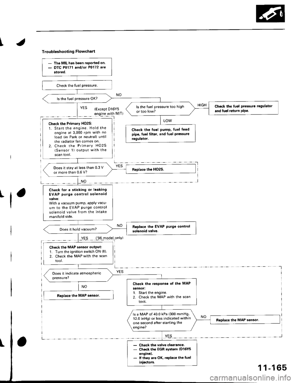
Troubleshooting Flowchart
'l
NO
a-,-:- -
YES
- The MIL ha3 b€on rePorled on.- DTC P0171 a^dlot P0172 arc
stored,
is the fuel pressure OK?
Check the fuel pt€ssure regulator
and fusl re{urn pipe.ls the fuel pressure too high
ortoo low?
Check the Primary HO2S:
1. Start the engine. Hold the
engine at 3,000 rpm with no
Ioad (in Park or neutral) until
the radiator Ian comes on
2. Check the Primary HO2S(Sensor 1) output with the
scan tool,
Check the tu6l pump. fuel leedpipe, fu€l fiher, and Iuel Pressureregulator.
Does it stay at less than 0.3 V
or more than 0.6 V?
Check lor a sticking or leaking
EVAP purge control solenoid
With a vacuum PumP, aPPIY vacu-
um to the EVAP purge control
solenoid valve from the intake
manifold side.
Does it hold vacuum?
Check the MAP sensor outputr
1. Turn the ignition switch ON (ll)
2. Check the MAP with the scan
tool.
Check th6 response of the MAP
sensoa:1. Start the engine.2. Check the MAP with the scan
tool.
ls a MAP of 40.0 kPa 1300 mmHg,12.0 inHg) or less indicated within
one second after starting the
engine?
- Check th€ valve cloarance.- Check the EGR rystem lD16Y5enginel.- lf they are OK, r€place the tueliniocto]3.
1 1-165
Page 436 of 2189
I
Misfire Detected in One Cylinder
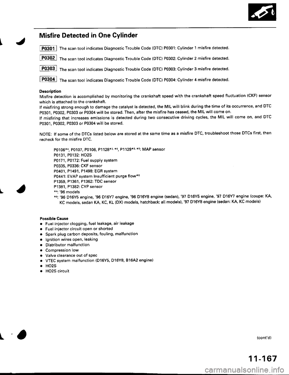
P0301 | The scan tool indicates Diagnostic Trouble Code (DTC) P0301: Cylinder 1 misfire detected.
[F03O2l 16"""untool indicates Diagnostic Trouble code (DTc) P0302: Cylinder2 misfire detected.
[FO3Ofl 16" ".un toot indicates Diagnostic Troubte Code (DTC) P0303; Cylinder 3 misfire detected.
I P0304 I ths..rr tool indicates Diagnostic Trouble Code (DTC) PO3O4: Cylinder 4 misfire detected.
D€scription
lMisfire detection is accomplished by monitoring the crankshaft speed with the crankshaft speed fluctuation (CKF) sensor
which is attached to the crankshaft,
lf misfiring strong enough to damage the catalyst is detected, the MIL will blink during the time of its occurrence, and DTC
PO3O1, P0302, PO3O3 or P0304 will be stored. Then, after the misfire has ceased, the MIL will come on.
lf misfiring that increases emissions is detected during two consecutive driving cyclss, the MIL will come on, and DTC
P0301, P0302, P0303 or P0304 will be stored.
NOTE: lf some of the DTCS listed below are stored at the same time as a misfire DTC, troubleshoot those DTCS first, then
recheck for the misfire DTC.
PO106*1, P0107, P0108. P1128*3'*5, P1129*3'*5: MAP sensor
P0131, P0132: HO2S
P0171, P0172iFuel suppiy system
P0335, P0336: CKF sensor
P0401. P1491, P1498: EGR system
P0441: EVAP system Insufficient purge flow*6
Pl359. P1361. Pl362: TDC sensor
P1381. Pl382: CYP sensor*o: '96 models*6: '96 D16Y5 engine,'96 D16Y/ engine,'96 D16Y8 engine {sedan),'97 D16Y5 engine,'97 D16\4, engine (coupe: KA,
KC models, sedan KA. KC, KL (DX) models, hatchback:all models),'97 D16Y8 engine (sedan: KA, KC models)
Possible Cause
. Fuel injector clogging, fuel leakage, air leakage
. Fuel injector circuit open or shorted
. Spark plug carbon deposits, fouling, malfunction
. lgnition wires open. leaking
. Distributor malfunction
. ComDression low
. Valve clearance out of spec
. VTEC system malfunction (D16Y5, D16Y8. 81642 engine)
. HO2S
. HO2S circuit
(cont'd)
11-167
r'a
Page 491 of 2189
ldle Control System
ldle Speed Setting (cont'dl
Inspeqtion/Adiustment
38 D16Y5 engine whh M/T,'99 - 00 81642 engine
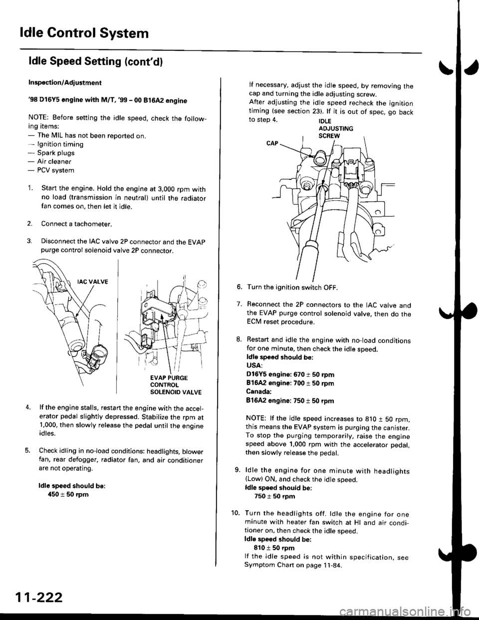
NOTE: Before setting the idle speed, check the follow-ing items;- The MIL has not been reported on.- lgnition timing- Spark plugs- Air cleaner- PCV system
'1. Start the engine. Hold the engine at 3,000 rpm withno load (transmission in neutral) until the radiatorfan comes on, then let it idle.
Connect a tachometer.
Disconnect the IAC valve 2P connector and the EVAPpurge controlsolenoid valve 2P connector.
EVAP PURGECONTROLSOLENOID VALVE
lf the engine stalls, restart the engine with the accel-erator pedal slightly depressed. Stabilize the rpm at1.000, then slowly release the pedal until the engineidles.
Check idling in no-load conditions: headlights, blowerfan, rear defogger, radiator fan, and air conditionerare not operating.
ldl€ speed should be:
450 i 50 rpm
11-222
lf necessary, adjust the idle speed, by removrng lnecap and turning the idle adjusting screw.After adjusting the idle speed recheck the ignitlontiming (see section 23). lf it is out of spec, go backto step 4. |DLE
6. Turn the ignition switch OFF.
7. Reconnect the 2P connectors to the IAC valve andthe EVAP purge control solenoid valve, then do theECM reset procedure.
8. Restart and idle the engine with no-load conditionsfor one minute, then check the idle sDeed.ldle speed should bo:
USA:
D16Y5 engine: 670 i 50 rpm
81642 engine: 700 i 50 rpm
Canada:
81642 engine: 750 t 50 rpm
NOTE: lf the idle speed increases to 8lO t 50 rpm,this means the EVAP system is purging the canister.To stop the purging temporarily, raise the enginespeed above 1,000 rpm with the accelerator pedal,
then slowly release the pedal.
9. ldle the engine for one minute with headlights(Low) ON. and check the idle speed.
ldle speed should be:
750 i 50 rpm
10. Turn the headlights off. ldle the engine for oneminute with heater fan switch at Hl and air condi-tioner on, then check the idle soeed.ldls speed should be:
810 t 50 rpm
lf the idle speed is not within specification, seeSymptom Chart on page 11-84.
Page 492 of 2189
\
I
'98 - 0O D16Y5 ongine with CvT
Adjust the idle speed using a Honda PGM Tester if pos-
sible. lf not, use the following procedure:
NOTE:
. Leave the IAC valve connected.
. Before s€tting the idle speed, check the following
rtems:- The MIL has not been reported on.
- lgnition timing
- Spark Plugs- Air clean€r
- PCV svstem
'1. Connect a tachometer.
2. Stan the engine. Hold the engine at 3,000 rpm w'th
no load (transmission in E or E] position) until the
radiator Jan comes on, then let it idle.
3. Check the idle speed under no-load conditions:
head lights, blower fan, rear defogger, radiator fan,
and air conditioner are not operatlng.
ldlo spaod ehould bo: 700 t 50 rpm
. lf the idle speed is within the specification, the
procedure is comPlete.
. lf the idle sDeed is out of specitication, 9o to step 4'
4. tf the idle speed is 810 1 50 rpm, this means the
EVAP system is purging the canister. To stop the
purging temporarily, raise the engine speed above
l,OO0 rgm with the accelsrator pedal. Slowly release
the pedal. and rscheck the idl€ speed.
. tf the idle speed is within the specificstion, the
Drocedure is comPlete.
. lf the idle sp€ed is out of spocification, go to step 5.
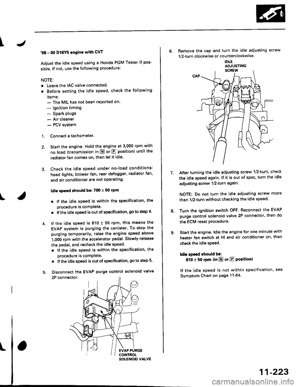
5. Disconnect th€ EVAP purgs control solenoid valve
2P connector.
EVAP PURGECONTROL
6. Remove the cap and turn the idle adiusting screw
1/2-turn clockwise or counterclockwlse
IDLE
7.After turning the idle adjusting screw 1/2-turn, check
the idl€ speed again. lf it is out of spec, turn the idle
adjusting screw 1/2-turn again.
NOTE: Do not turn the idle adjusting screw more
than 1/2-turn without checking the idle speed.
Turn the ignition switch OFF. Reconnect the EVAP
purge control solenoid valve 2P connector' then do
the ECM reset Procedure.
Start the engine. ldle the engine for one minute with
heater fan switch at Hl and air conditioner on, then
check the idle speed.
ldle spaed should be:
810 t 50 rpm (in El or E Posiiion)
lf the idle speed is not within specification, see
Svmptom Chart on Page 11-84.
9.
SOLENOID VALVE
11-223
Page 501 of 2189
Fuel Supply System
Fuel Injectors
Replacement
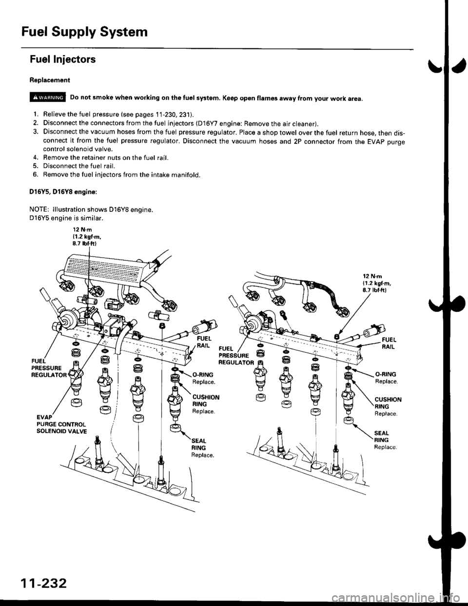
@ Do not smoke when working on the tuel systgm, Keep gp6n flames away from your work area
'f. Relieve the fuel pressure (see pages 11-230,231J.
2. Disconnect the connectors from thefuel injectors (D16Y7 engine: Remove the air cleaner).
3. Disconnect the vacuum hoses from thefuel pressure regulator. Placeashoptowel overthefuel return hose, then dis-connect it from the fuel pressure regulator. Disconnect the vacuum hoses and 2P connector from the EVAp purgecontrol solenoid valve.
4. Remove the retainer nuts on the fuel rail.
5. Disconnect the fuel rail.
6. Removethefuel injectors from the intake manifold.
D16Y5, D16Y8 engine:
NOTE: lllustration shows D16Y8 engine.
D16Y5 engine is similar.
12 N.m11.2 kgl.m,8.7 rbt.ft)
12 N.m11.2 lgl.m,8.7 rbt.ftl
.q
wE4
Y
Ve
ffi}Yg
E
O.RINGReplace.
CUSHIONRINGReplace.
O.RINGReplace.
cusl{toNRINGReplace.
SEALRINGReplace.
ffi
E
EV
R
w
t
YEVAPPURGE CONTNOLSOLENOID VALVE
FUEL
11-232
Page 502 of 2189
\J
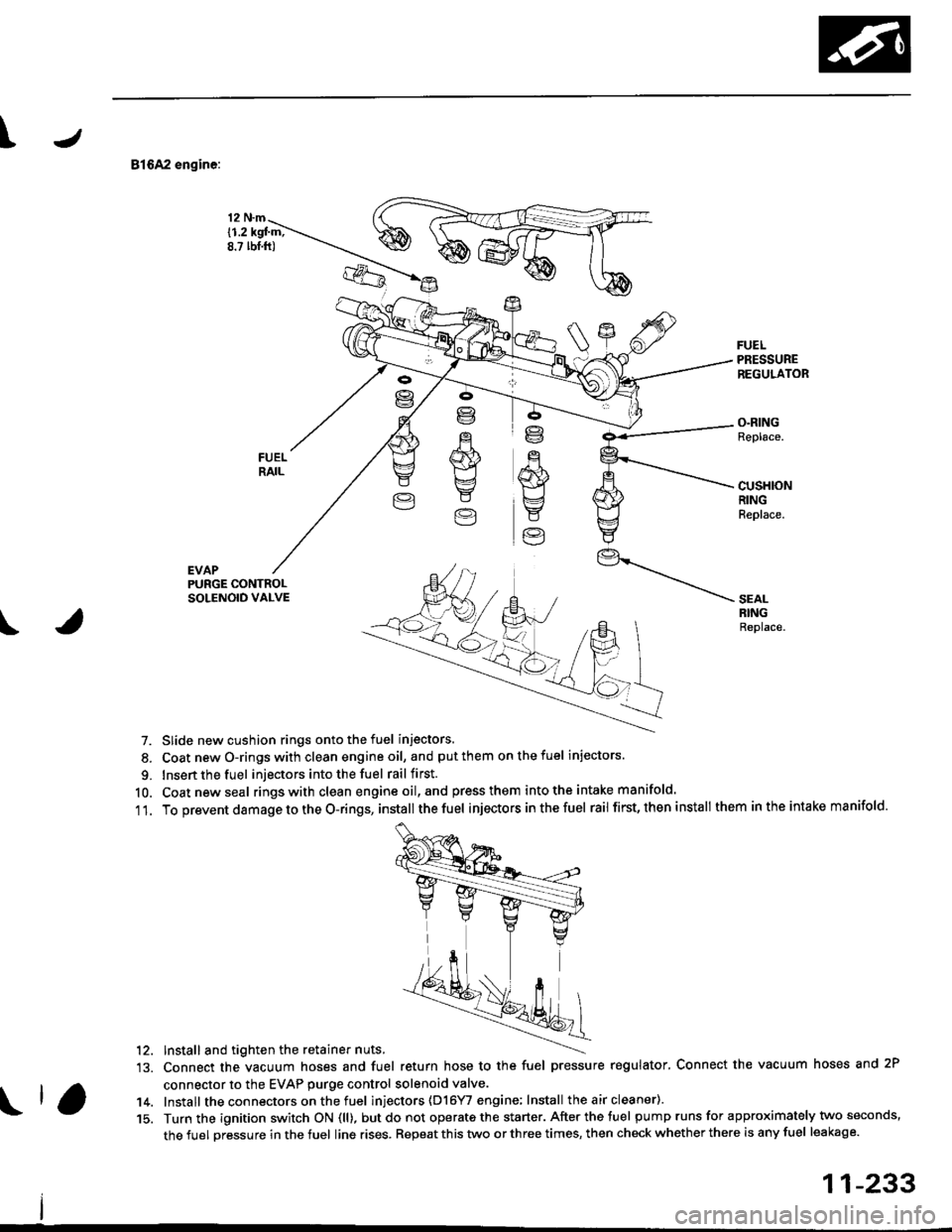
81642 engine:
EVAP
12 N.m
{1.2 kgl m;8.? lbt.ft)
FUELPRESSUREREGULATOR
O.RINGReplace.
cusHloNRINGReplace.
PURGE CONTROLSOLENOID VALVE
\
SEALRINGReplace.
7. Slide new cushion rings onto the fuel injectors.
8. Coat newO-ringswith clean engineoil, and putthem onthefuel injectors.
9. Insert the fuel injectors into the fuel rail first.
10. Coatnewseal rings with clean engine oil,and press them intothe intake manifold.
11. To prevent damage to the O-rings, installthe fuel injectors inthefuel rail first, then install them inthe intake manifold.
'12. Install and tighten the retainer nuts.
13. Connect the vacuum hoses and fuel return hose to the fuel pressure regulator, Connect the vacuum hoses and 2P
connector to the EVAP purge control solenoid valve.
14. Install the connectors on the fuel inl'ectors (D16YI engine; Install the air cleaner).
15. Turn the ignition switch ON (ll), butdo not operate the starter. After the tuel pump runs for approximately two seconds,
the fuel pressure in the fuel line rises. Repeat this two or three times, then check whether there is any fuel leakage.
11-233
Page 521 of 2189
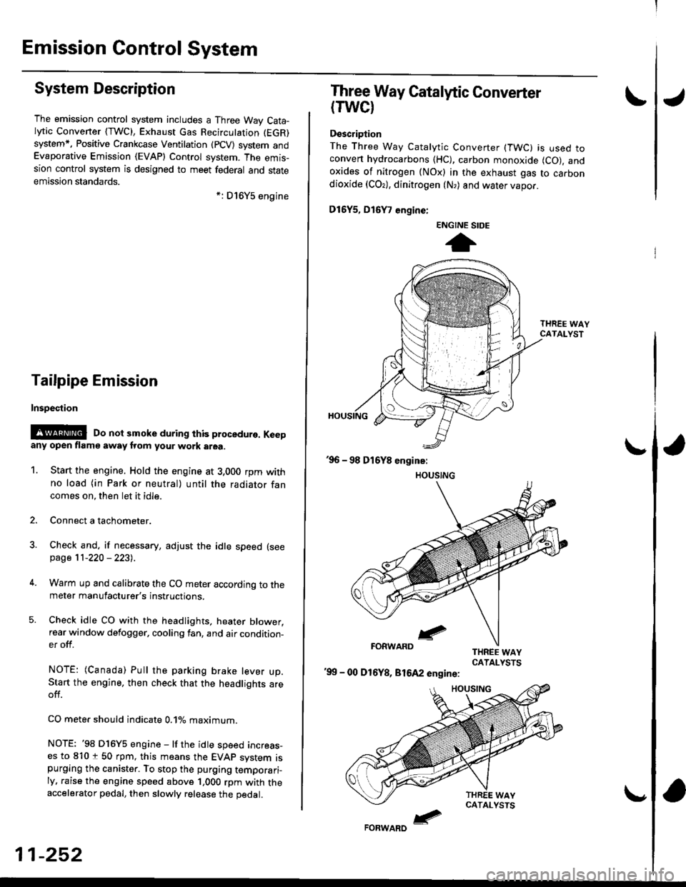
Emission Gontrol System
System Description
The emission control system includes a Three Way Cata-lytic Convener (TWC), Exhaust Gas Recirculation (EGR)
system,. Positive Crankcase Ventilation (pCV) system andEvaporative Emission (EVAP) Control system. The emis-sion control system is designed to meet federal and stateemission standards.*: D16Y5 engine
Tailpipe Emission
Inspestion
@@ Do not smoke during ihis procedure. Keepany open flame away from your work area.
1. Start the engine. Hold the engine at 3,000 rpm withno load (in Park or neutral) until the radiator fancomes on. then let it idle.
2. Connect a tachometer.
Check and, if necessary, adjust the idle speed (see
page 11-220 - 223).
Warm up and calibrate the CO meter according to themeter manufacturer's instructions.
Check idle CO with the headlights, heater blower,rear window defogger, cooling fan, and air condition-er off.
NOTE: (Canada) Pull the parking brake lever up.Start the engine, then check that the headlights areoff.
CO mete. should indicate 0.1% maximum.
NOTE: '98 Dl6Y5 engine - lf the idle speed incress-es to 8101 50 rpm, this means the EVAp system ispurging the canister. To stop the purging temporari-ly. raise the engine speed above 1,000 rpm with theaccelerator pedal, then slowly release the pedal.
11-252
eFORWARD -
Three Way Catalytic Converter
(TWCI
Doscription
The Three Way Catalytic Converter (TWC) is used toconven hydrocarbons (HC), carbon monoxide (CO), andoxides of nitrogen (NOx) in the exhaust gas to carbondioxide (COr), dinitrogen (N,) and water vapor.
D15Y5, D16
, engine:
'99 - 00 D16Y8, 81642 engine:
ENGINE SIDE
t
Page 536 of 2189
1\
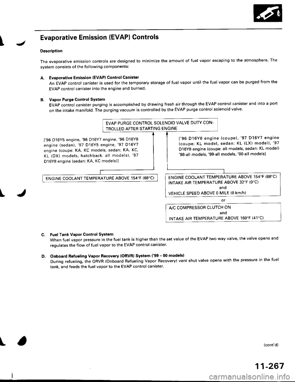
Evaporative Emission (EVAPI Controls
Description
The evaporative emission controls are designed to minimize the amount of fuel vapor escaping to the atmosphere. The
system consists of the foliowing components:
A. Evaporative Emission (EVAP) Control Canisto]
An EVAP control canister is used for the temporary storage of fuel vapor until the fuel vapor can be purged from the
EVAP control canister into the engine and burned.
B. Vapor Purge Control System
EVAP control canister purging is accomplished by drawing fresh air through the EVAP control canister and into a port
on the intake manifold. The purging vacuum is controlled by the EVAP purge control solenoid valve.
I'96 D16Y5 engine,'96 Dl6Y7 engine,'96 D16Y8
engine (sedan),'97 D16Y5 engine,'97 D16Y7
engine (couper KA, KC models, sedan: KA, Kc'
KL iDX) models, hatchback: all models), '97
D 16Y8 engine (sedan: KA, KC models)l
I'96 D16Y8 engine (coupe),'97 D16Y7 engine
(coupe: KL model, sedan: KL (LX) model)"97
D16Y8 engine (coupe: all models, sedan: KL model)'98-all models,'99-all models,'00-all modelsl
I
c.
D.
or
l'lc COMPRESSOR CLUTCH ON
and
INTAKE AIR TEMPERATURE ABOVE 160"F (41'C)
Fuel Tank Vapor Control System
When fuel vapor pressure in the fuel tank is higher than the set value of the EVAP two way valve, the valve opens and
regulates the flow of fuel vapor to the EVAP control canister.
Onboard Refueling Vapor Recovery (ORVRI System {'99 - 00 models}
During refueling. the oRVR {onboard Refueling Vapor Recovery) vent shut valve opens with the pressure in the fuel
tank. and feeds the fuel vapor to the EVAP control canister.
t(cont'd)
11-267
EVAP PURGE CONTROL SOLENOID VALVE DUTY CON-
TROLLED AFTER STARTING ENGINE
ENGINE COOLANT TEMPERATURE ABOVE 154'F {68"C)
INTAKE AIR TEMPERATURE ABOVE 32'F (O'C)
and
VEHICLE SPEED ABOVE O MILE (O KM/h}
ENGINE COOLANT TEMPERATURE ABOVE 154'F (68'C)