Turn signal HONDA CIVIC 2000 6.G Manual PDF
[x] Cancel search | Manufacturer: HONDA, Model Year: 2000, Model line: CIVIC, Model: HONDA CIVIC 2000 6.GPages: 2189, PDF Size: 69.39 MB
Page 1817 of 2189

Contents
How to Use This Manual ICircuit Schematics (see Circuit Index)Fuse/Relaylnformation 6Ground-to-Componentslndex 6-6ComponentLocationPhotooraohs 201Conriector Views 202
Circuit Index
Accessory power socket 155Air conditionerAir delivery'96198 models 61'99-'00 models 61-2Blower controls'96198 models 60'99100 models 60-1Compressor controls 62Fans 63Anti-lock brake system (ABS) 44A/T gear position indicatorCVT 89All except CVT 89-1Automatic transmission controlsAll '96-'98 models except CVT and GX 39All '99100 models except CVT 39-8All GX models 39-8'96-'�98 CVT 39-4'99100 cw 39-12Back-up lightsCoupe and Sedan 110Hatchback l'10-1Brake lightsAll Coupes and'96-'98 Sedans 110-15'99-'00 Sedans 110-16Hatchback 110-17Brake system indicator light'96198 models 7'1'99100 models 71-1Ceiling light 114-3Charging system 22Condenser fan 63Console lights 114Cruise control 34Dash lights 114Daytime running lights 110- 13Engine coolant temperature gauge 81-1Fog lights 110-10Front parking lights 110-2Fuel gauge 81-1Fuse/relay boxUnder-dash 6Under-hood 6-4Underhood ABS 6-3Gauges 81Ground distribution 14Ground-to-Componentslndex 6-6Hazard warning lightsAll except '99100 Sedans 110-6'99100 Sedans 110-8Headlights 110-12Headlight switch 100Heater - See Air ConditionerHorn'96197 models 40'98 model 40-1'99100 models 40-2lgnition key reminder 73lgnition systemAll '96198 models except Dl685 20All '99100 models except D16Y5 with Mn 2O-2All D1685 engines 20-2'99-'00 D 16Y5 with M/T 20
lndicators 80Integrated control unit 70lnterlock systemAll except'96J98 CVT 138'96198CVT 138-1License plate lightsAll Coupes and '96-'98 Sedans I l0-3'99100 Sedans 1 10-4Hatchback 110-5Low fuel indicator light 74Moonrool'96197 models |22'98-'00 models 122-1Odometer 81Oil pressure indicator light 80-3Power distributionBattery to ignition switch, fuses, and relaysFuses to relays and components 10-2Power door locksAll models without keyless entry 130'96-'98 models with keyless entry 130-2'99100 models with keyless entry 130-12Power mirrorsWithout detogger 141With defogger '141-2
Power windows 120Programmed fuel injection system (PGNr-Fl)All '96-98 models except D1685 23All '99-'00 models except D16Y5with M/T and D1685 24All D1685 engines 25'99100 D16Y5 with M/T 23Radiator fan 63Rear window defogger'96-,98 models 64'99100 models 64-1Seat belt reminder 73Security system'96.'98 USA HX, LX, EX 133'96-'98 Canada EX, Si 133'99TOO USA HX, LX, EX, DX.V Si 133-4'99100 Canada EX, Si 133-4All CX and DX models 133-8Speedometer 81Starting systemA./T (All except Dl685) 21A"/r (D16Bs) 21-1Manualtransmission 21-2Slereo sound system 150Supplemental rastraint system (SRS) 47Tachometer 81TailliqhtsAllboupes and'96-'98 Sedans 110-3'99100 Sedans 1 10-4Hatchback 110-5Trunk light 114-3Turn signal lightsAll except'99100 Sedans 110-6'99-'00 Sedans 1 10-8Vehicle speed sensor (VSS) 33Wiper/washerFront 91Rear 92
10
Page 1840 of 2189

Ground-to-Components I ndex
f.,lONOTE: All ground wires are BLK unless otherwise noted.
GroundPageComponents or Circuit Grounded
Battery (BLKYEL)
Steering pump bracket
t+-rg ITransmission housing
l
G101
(-1)
G101
(-2)
14-2
and
14-3
ano
14-1
Powertrain or engine control module (PG1 and pG2 are BLK: LG1 and LG2 are
BRN/BLK), EGR control solenoid valve (CW, EGR valve and lift sensor (Dt6yS enginewith M,/T), Engine coolant temperature switch, pGM-Fl main relay, power steeringpressure switch (USA), Primary HO2S (D16Y5 engine with l\/,/T), Vehicle speed sensor,VTEC pressure switch (D16Y5/D16Y8 engines), CKF sensor (BRN/BLK), Transmission
control module (CYf) (Pc1 is BLK: LG1 is BRN/BLK)
Shielding betvveen the PCM or ECM and these components (all have BRN/BLK wires):
CKF sensor, TDC/CKP/CYP sensor. Primary and secondary heated oxygen sensors.
Knock sensor (CWDl6YB engine), Mainshaft speed sensor (AiT except CVT),
I Countershaft speed sensor (A/T except CVf)
Shielding between the TCM and these components (CVT) (all have BRN/BLK wires):
Drive pulley speed sensor, Driven pulley speed sensor, Secondary gear shaft
speed sensor
Powertrain or engine control module (PG1 and pG2 are BLK; LG1 and LGz are
BRN/BLK), EGR control solenoid valve (D16Y5 engine), EGR valve (Dt685), Engine
coolant temperature switch, Fuel pressure regulator shut-off solenoid valve (D1685),
PGM-FI main relay, Power steering pressure switch (USA), Vehicle speed sensor, VTECpressure switch (All except D16Y7 engine), CKF sensor (A
except 81642) (BRN/BLK)
Shielding between the PCM or ECM and these components (all have BRN/BLK wires):
CKF sensor, TDC/CKP/CYP sensor, Primary and secondary heated oxygen sensors,
Knock sensor (All except D16Y7 engine), i/ainshaft speed sensor (Arf except CW),
Countershaft speed sensor (A,/T except CVf), Drive pulley speed sensor (CW), Drivenpulley speed sensor (CVT), Secondary gear shaft speed sensor (CVf)
I Badiator fan motor, Right front parking/turn signat tight, Right headtight
G20214-4I Cruise control actuator, Left front parking/turn signal lights, Left headlight, Rear window
I washer motor, Windshield washer motor, Washer fluid level switch (,99-'00 Canada)
G401| +-o
and
14-7
Accessory power socket, Brake fluid level switch, Clutch interlock switch (M/T), Clutchswitch (lillT with cruise/D16Y5 engine with MfD, Combination wiper switch (Z wires),
Cruise control main switch, Cruise control unit, Dash lights brightness controller, Data
link connector, Daytime running lights control unit (Canada), Gauge assembly, Horn('96-'97 models), Integrated control unit, Interlock control unit (ArI), Keyless door lock
control unit ('99-'00 models with keyless), Moonroof close and open relays, Moonroof
switch, Park pin switch (A/r), Power window relay, Rear window defogger relay, Rear
window defogger switch ('96-'98 models), Steering lock, Stereo radio tuner (,96-,98
USA: LX, EX, and HX), Turn signal/hazard relay, Windshield wiper motor.....plus
everything grounded through G402
6-6
Page 1841 of 2189
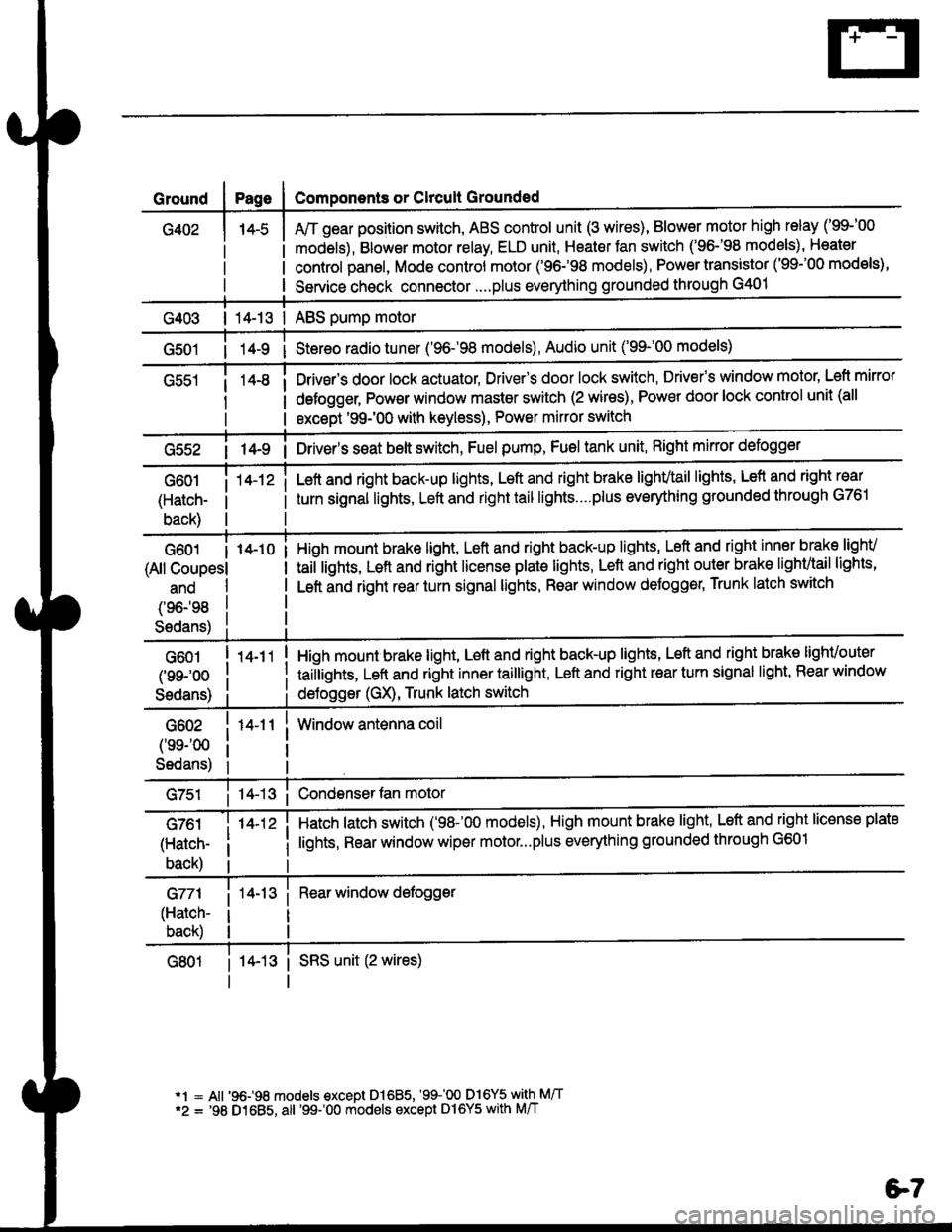
Ground
G402
Components or Clrcult Grounded
Arr gear position switch, ABS control unit (3 wires), Blower motor high relay ('99-'00
models), Blower motor relay, ELD unit, Heater Jan switch ('96-'98 models), Heater
control panel, Mode control motor ('96.�98 models), Power transistor ('99-'00 models),
Service check connector....plus everything grounded through G401
| 14-13 | ABS pump motor
1l-9 i Stereo radio tuner ('96-'98 models), Audio unit ('99-'00 models)
Drivsr's door lock actuator, Driver's door lock switch, Drivefs window motor' Left mirror
defogger, Pow€r window master switch (2 wires), Power door lock control unit (all
except '99-'00 with keyless), Power mirror switch
G55214-9 i Driver's s€at belt switch, Fuel pump, Fuel tank unit, Right mkror defogger
G601
(Hatch-
back)
14-12 iLeft and right back-up lights, Left and right brake lighvtail lights, Lefl and right rear
turn signal lights, Left and right tail lights....plus eveMhing grounded through G761
G601 I 14-10
(All Coupesl
ano
(96198
S6dans)
High mount brake light, Left and right back-up lights, Left and right inner brake lighv
taiilights, Lett and right license plale lights, Lett and right outer brak€ lighvtail lights'
Left and right rear turn signal lights, Rear window deJogger, Trunk latch switch
G601
(99-'oo
Sedans)
G602
('ss-'00
Sedans)
G761
(Hatch-
back)
G771
(Hatch-
back)
14-11
14-12 i
High mount brake light, Left and right back-up lights, Left and right brake lighvouter
taillights, Left and right inner taillight, Left and right rear turn signal light' Rear window
deJogger (GX), Trunk latch switch
Window antenna coil
Hatch latch switch ('98-'00 models), High mount brake light' Left and right license plate
lights, Rear window wiper motor...plus everything grounded through G601
Rear window defogger
14-13 i SRS unit (2 wires)
*1 = All '96-98 models €xcept Dl685, '99100 D16Y5 with M/T*2 = '98 D1685, all '99-'00 models except Dl6Y5 with M/T
e7
Page 1861 of 2189
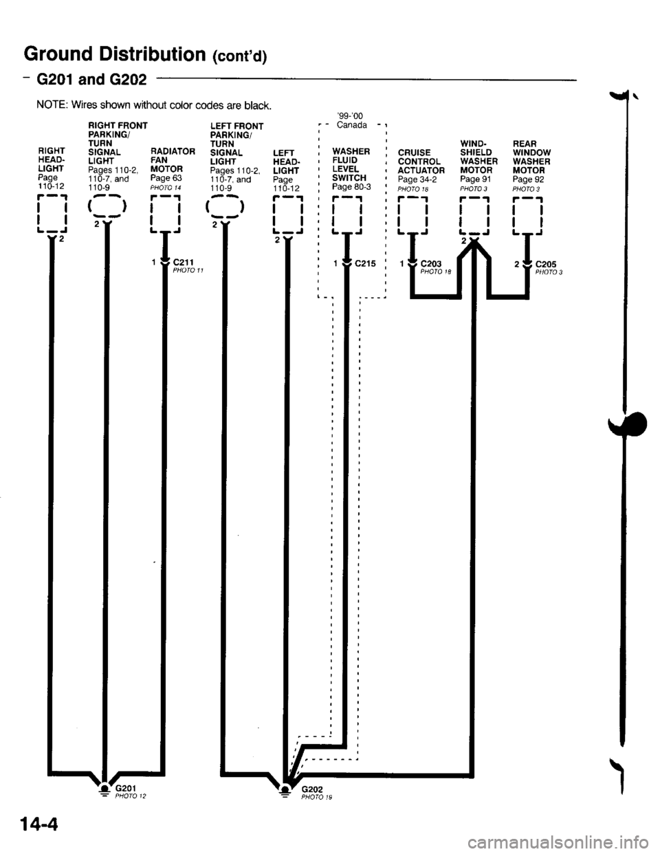
Ground Distributiofl (cont'd)
- G201 andG202
NOTE: Wires shown wrthout color codes are black.
RIGHTHEAD.LIGHTPage110-12
tl
tl
110-9
{}tl
tl
LEFT FRONTPARKING/TURNSIGNALLIGHTPages 110-2,1 10-7, and110-9
()
WIND.SHIELDWASHERMOTORPage 91PHOTA 3
ll
tl
REARwtNDowWASHERMOTORPage 92
tl
tt
c205
RIGHT FRONTPARKING/TURNStcNAL RADIATORLIGHT FANPaoes 110-2, MOTOR11d-7, and Page 63
'99-'�00
.- Canada -l
i wnsxen i cnurse, FLUID ; CONTROL' LEVEL . ACTUATOR' SWITCH I paoe 34-2; Page 80-3 i eu6ro re'f-1 ' f-1
2Y2
c211
14-4
I'G201'Lv G2o2
Page 1867 of 2189
l
RIGHTOUTERBRAKE LIGHT/TAIL LIGHTPages 110-3and 110-15
(l
RIGHTREARTURNSIGNALLIGIITPage 110-7
l-
LEFTREARTURNSIGNALLIGHTPage 110-7
l-
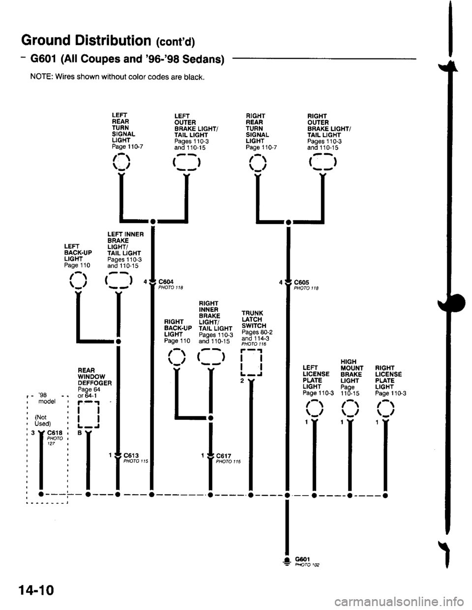
Ground Distributior (cont'd)
- G601 (All Coupes and'96-'98 Sedans)
NOTE: Wires shown without color codes are black.
LEFTOUTERBRAKE LIGHT/TAIL LIGHTPages 110-3and 110-15
()
LEFTBACK.UPLIGHTPage 110
LEFT INNERBRAKELIGHT/IAIL LIGHTPages 110-3and 1 10-15
( )4c604c605
RIGHTBACK.UPLIGHTPage 110
FIGHTINNERBRAKELIGHT/TAIL LIGHTPages 110-3and 110-15
()
TRUNKLATCHswtTcHPages 80-2and 114-3
tl
!l
2
HIGHIUOUNT RIGHTBRAKE LICENSELIGHT PLATEPaoe LIGHT11d-15 Page 110-3
/-t /-t\_/ \_/
II-a----o
LEFTLICENSEPLATELIGHTPage 110-3
\,,
REARwtNDowDEFFOGERPaoe &'-'98 -, or 5a-1I mooet ' r-.1
: :r I
I tl?l,r i L_J
i'l'* i
'l
: .---.-.---a
c6't 3
G@1
14-10
Page 1869 of 2189
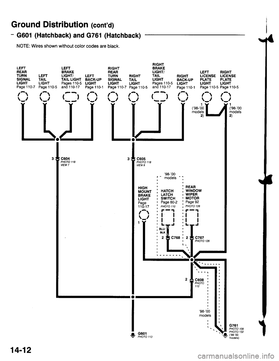
Ground Distribution (cont'd)
- G601 (Hatchback) and G761 (Hatchback)
NOTE: Wires shown without color codes are black.
LEFTREARTURNSIGNALLIGHTPage 110-7
LEFTTAILLIGHTPage 110-5
LEFTERAKELIGHT/TAIL LIGHTPages 110-5and 110-17
()
LEFTBACK.UPLIGHTPage 1 10-1
RIGHTREARTUNN FIGHTSIGNAL TAILLIGHT LIGHTPage 110-7 Page 110-5
RIGHTBRAKELIGHTiTAILLIGHTPages 110-5and 110-17
()
: HATCH; LATCH, swrTcH' Page 80-2' PHO|O 11A
:l I;l I
. BLU/I BLK
i2
'98-'�00
models ' :
:t I
i L-J
czsa izlczszPHO|O 126
LEFT RIGHTLICENSE LICENSEPLATE PLATELIGHT LIGHTPage 110-5 Page 110-5
/-.t r-t\_,, \_,,I(98-'00mooets2)
G761PHOTO 109PHO|O 132(98i00
RIGHTBACK.UPLIGHTPage 1 10- l
c605
vlEw a
HIGHMOUNTBRAKELIGHTPage110- t7
G601
: REAR; wlNDow. WIPER, MOTOR' Page 92
r-t lr-t\_, \_,,
II
ll
l-y-
14-12
'.!
Page 1922 of 2189
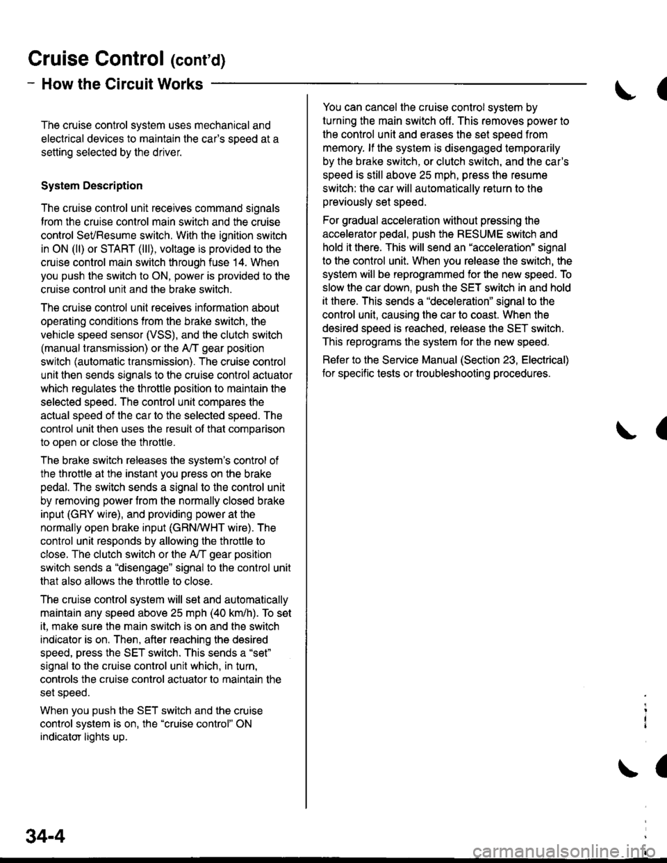
Gruise Control (cont'd)
- How the Circuit Works
The cruise control system uses mechanical and
electrical devices to maintain the car's sDeed at a
setting selected by the driver.
System Description
The cruise control unit receives command signals
from the crurse control main switch and the cruise
control SeVResume switch. With the ignition switch
in ON (ll) or START (lll), voltage is provided to the
cruise control main switch through fuse 14. When
you push the switch to ON, power is provided to the
cruise control unit and the brake switch.
The cruise control unit receives information about
operating conditions from the brake switch, the
vehicle speed sensor (VSS), and the clutch switch
(manual transmission) or the A,/T gear position
switch (automatic transmission). The cruise control
unit then sends signals to the cruise control actuator
which regulates the throttle position to maintain the
selected speed. The conlrol unit compares the
actual speed of the car to the selected speed. The
control unit then uses the result of that comoarison
to open or close the throttle.
The brake switch releases the system's control of
the throttle at the instant you press on the brake
pedal. The switch sends a signal to the control unit
by removing power from the normally closed brake
input (GRY wire), and providing power at the
normally open brake input (GRN/vVHT wire). The
control unit responds by allowing the throttle to
close. The clutch switch or the A,/T gear position
switch sends a "disengage" signal to the control unit
that also allows the throttle to close.
The cruise control system will set and automatically
maintain any speed above 25 mph (40 km/h). To set
it, make sure the main switch is on and the switch
indicator is on. Then, after reaching the desired
speed, press the SET switch. This sends a "set"
signal to the cruise control unit which, in turn,
controls the cruise control actuator to maintain the
set speed.
When you push the SET switch and the cruise
control system is on, the "cruise control" ON
indicator lights up.
34-4
(
You can cancel the cruise control system by
turning the main switch off . This removes power to
the control unit and erases the set speed from
memory. lf the system is disengaged temporarily
by the brake switch, or clutch switch, and the car's
speed is still above 25 mph, press the resume
switch: the car will automatically return to the
previously set speed.
For gradual acceleration without pressing the
accelerator pedal, push the RESUME switch and
hold it there. This will send an "acceleration" signal
to the control unit. When you release the switch, the
system will be reprogrammed for the new speed. To
slow the car down. oush the SET switch in and hold
it there. This sends a "deceleration" signal to the
control unit, causing the car to coast. When the
desired speed is reached, release the SET switch.
This reprograms the system tor the new speed.
Refer to the Service Manual (Section 23, Electrical)
tor specific tests or troubleshooting procedures.
(
a
Page 1964 of 2189
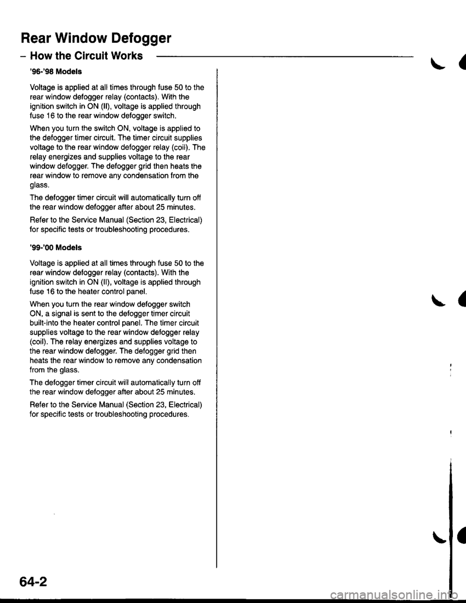
Rear Window Defogger
- How the Circuit Works
'96198 Models
Voltage is applied at all limes through tuse 50 to the
rear window detogger relay (contacts). With the
ignition switch in ON (ll), voltage is applied through
tuse 16 to the rear window defogger switch.
When you turn the switch ON, voltage is applied to
the defogger timer circuit. The timer circuit supplies
voltage to the rear window defogger relay (coil). The
relay energizes and supplies voltage to the rear
window defogger. The defogger grid then heats the
rear window to remove any condensation from the
glass.
The defogger timer circuit will automatically turn off
the rear window defogger after about 25 minutes.
Refer to the Service Manual (Section 23, Electrical)
for specific tests or troubleshooting procedures.
'99100 Models
Voltage is applied at all times through fuse 50 to the
rear window delogger relay (contacts). With lhe
ignition switch in ON (ll), voltage is applied through
fuse 16 to the heater control oanel.
When you turn the rear window defogger switch
ON, a signal is sent to lhe defogger timer circuit
built-into the heater control oanel. The timer circuit
supplies voltage to the rear window defogger relay
(coil). The relay energizes and supplies voltage to
the rear window defogger. The defogger grid then
heats the rear window to remove anv condensation
from the glass.
The defogger timer circuit will automatically turn otf
the rear window defogger after about 25 minutes.
Refer to the Seryice Manual (Section 23, Electrical)
for specific tesls or troubleshooting procedures.
64-2
I
a
a
Page 1980 of 2189
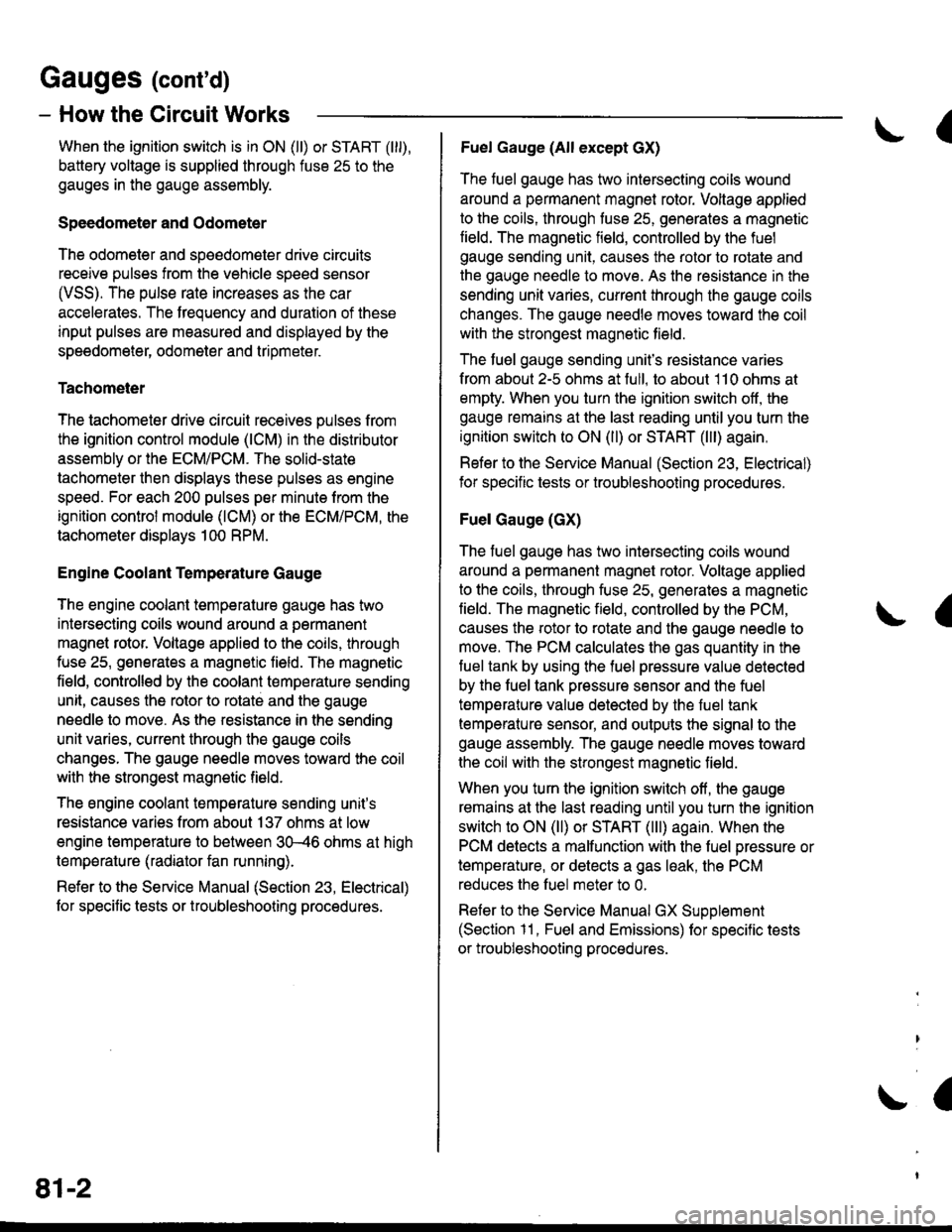
Gauges (cont'd)
- How the Gircuit Works
When the ignition switch is in ON (ll) or START (lll),
battery voltage is supplied through fuse 25 to the
gauges in the gauge assembly.
Speedometer and Odometer
The odometer and soeedometer drive circuits
receive pulses from the vehicle speed sensor
(VSS). The pulse rate increases as the car
accelerates. The frequency and duration of these
input pulses are measured and displayed by the
speedometer, odometer and tripmeter.
Tachometer
The tachometer drive circuit receives pulses from
the ignition control module (lCM) in the distributor
assembly or the ECM/PCM. The solid-state
lachometer then displays these pulses as engine
speed. For each 200 pulses per minute from the
ignition control modul€ (lCM) or the ECM/PCM, the
tachometer displays 100 RPM.
Engine Coolant Temperature Gauge
The engine coolant temperature gauge has two
intersecting coils wound around a permanent
magnet rotor. Voltage applied to the coils, through
fuse 25, generates a magnetic lield. The magnetic
field, controlled by the coolant temperature sending
unit, causes the rotor to rotate and the gauge
needle to move. As the resistance in the sending
unit varies, current through the gauge coils
changes. The gauge needle moves toward the coil
with the strongest magnetic field.
The 6ngine coolant temperature sending unit's
resistance varies from about 137 ohms at low
engine temperature to between 3H6 ohms at high
temperature (radiator fan running).
Refer to the Service Manual (Section 23, Electrical)
for specific tests or troubleshooting procedures.
81-2
(
Fuel Gauge (All except cX)
The fuel gauge has two intersecting coils wound
around a permanent magnet rotor. Voltage applied
to the coils, through tuse 25, generates a magnetic
field. The magnetic field, controlled by the fuel
gauge sending unit, causes the rotor to rotate and
the gauge needle to move. As the resislance in the
sending unit varies, current through the gauge coils
changes. The gauge needle moves toward the coil
with the strongest magnetic field.
The fuel gauge sending unit's resistance varies
from about 2-5 ohms at full, to about 110 ohms at
empty. When you turn the ignition switch off, the
gauge remains at the last reading until you turn the
ignition switch to ON (ll) or START (lll) again,
Refer to the Service Manual (Section 23, Electrical)
for specific tests or troubleshooting procedures.
Fuel Gauge (GX)
The fuel gauge has two intersecting coils wound
around a permanent magnet rotor. Voltage applied
to the coils, through fuse 25, generates a magnetic
field. The magnetic field, controlled by the PCM,
causes the rotor to rotate and the gauge needle to
move. The PCM calculates the gas quantity in the
fuel tank by using the fuel pressure value detected
by the tuel tank pressure sensor and the fuel
temperature value detected by the fuel tank
temperalure sensor, and outputs the signal to the
gauge assembly. The gauge needle moves toward
the coil with the strongest magnetic field.
When you turn the ignition switch off , the gauge
remains at the last reading until you turn the ignition
switch to ON (ll) or START (lll) again. When the
PCM detects a malfunction with the fuel pressure or
temperature, or detects a gas leak, the PCM
reduces the fuel meter to 0.
Refer to the Service Manual GX Supplement
(Section 11 , Fuel and Emissions) for specific tests
or troubleshooting procedures.
a
a
Page 1986 of 2189
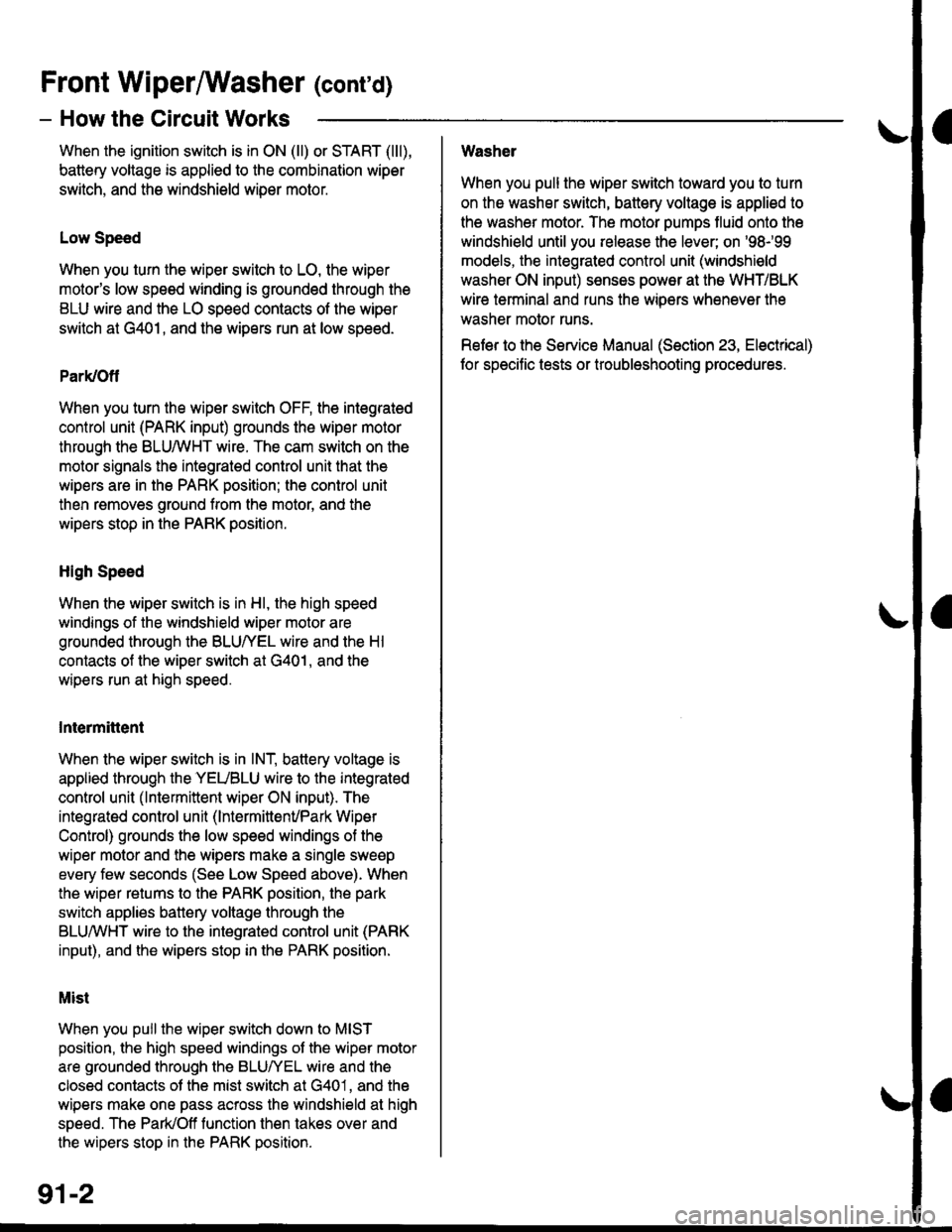
Front WiperMasher (cont'd)
- How the Circuit Works
When the ignition switch is in ON (ll) or START (lll),
battery voltage is applied to lhe combination wiper
switch. and the windshield wiDer motor.
Low Speed
When you turn the wiper switch to LO, the wiper
motor's low speed winding is grounded through the
BLU wire and the LO speed contacts of the wip€r
switch at G401, and the wipers run at low speed.
ParUOfl
When you turn the wiper switch OFF, the integrated
control unit (PARK input) grounds the wiper motor
through the BLUMHT wire. The cam switch on the
motor signals the integrated control unit that the
wipers are in the PARK position; the control unit
then removes ground from the motor, and the
wipers stop in the PARK position.
High Speed
When the wiper switch is in Hl, the high speed
windings of the windshield wiper motor are
grounded through the BLUIrEL wire and the Hl
contacts of the wiper switch at G401, and the
wipers run at high speed.
Intermittent
When the wiper switch is in lNT, battery voltage is
applied through the YEUBLU wire to the integrated
control unit (lntermittent wiper ON input). The
integrated control unit (lnt€rmittenvPark Wiper
Control) grounds the low speed windings of the
wiper motor and the wipers make a single sweep
every few seconds (See Low Speed above). When
the wiper retums to the PARK position, the park
switch applies battery voltage through the
BLUMHT wire to the integrated control unit (PARK
input), and the wipers stop in the PARK position.
Mist
When you pull the wiper switch down to MIST
position, the high speed windings ot the wiper motor
are grounded through the BLU^/EL wire and the
closed contacts ot the mist switch at G401, and the
wipers make one pass across the windshield at high
speed. The ParUOff function then takes over and
the wipers stop in the PARK position.
Washel
When you pull the wiper switch toward you to turn
on the washer switch, battery vollage is applied to
the washer motor. The motor pumps fluid onto the
windshield until you release the lever; on '98r99
models, the integrated control unit (windshield
washer ON input) s€nses power at the WHT/BLK
wire terminal and runs the wipers whenever the
washer motor runs.
Refer lo the Service Manual (Seclion 23, Electrical)
for specific tests or troubleshooting procedures.
91-2