ACC unit HONDA CIVIC 2000 6.G Workshop Manual
[x] Cancel search | Manufacturer: HONDA, Model Year: 2000, Model line: CIVIC, Model: HONDA CIVIC 2000 6.GPages: 2189, PDF Size: 69.39 MB
Page 62 of 2189
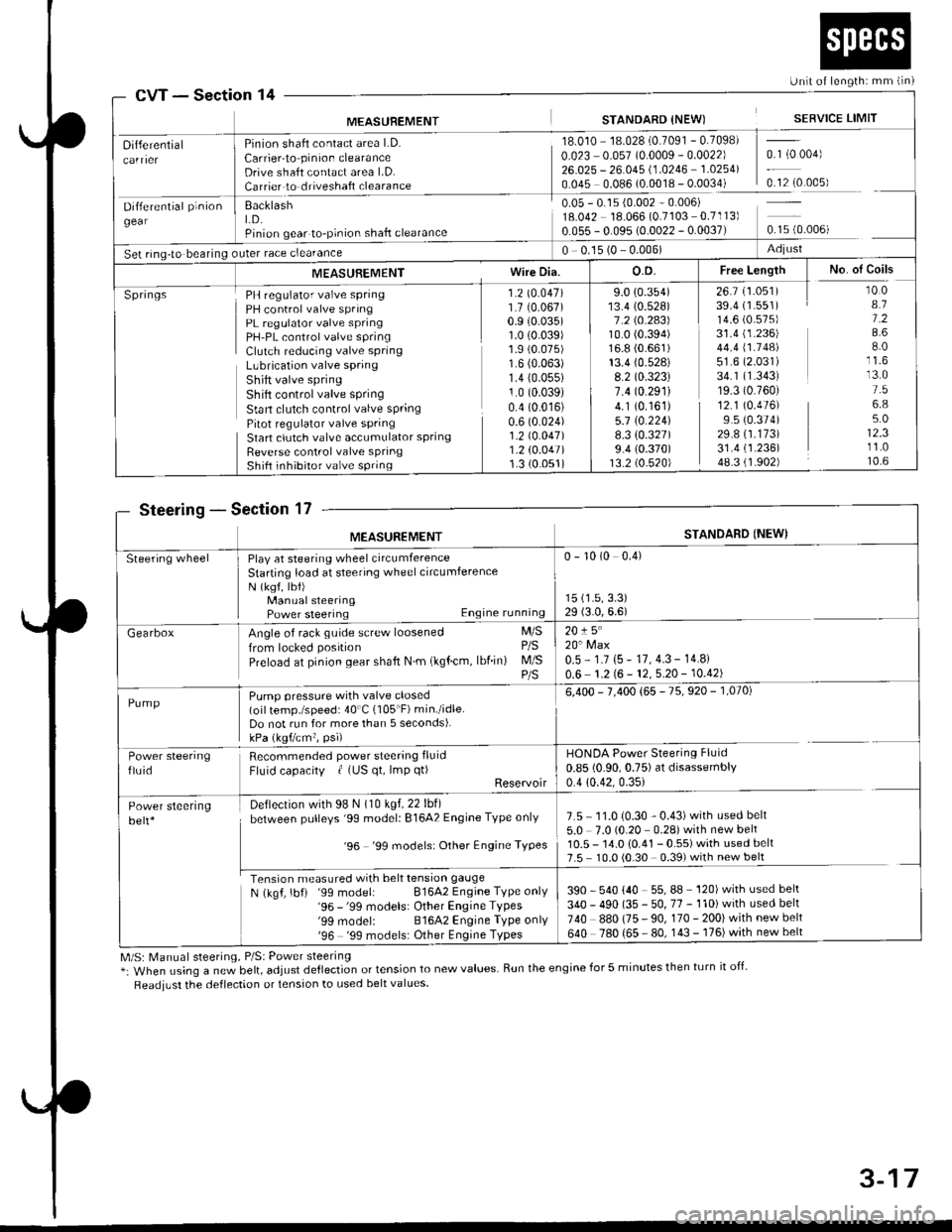
Unit of length: mm lin)
STANDARD {NEW) SERVICE LIMITMEASUREMENT
Differential
Dtri"*"t"|p'.b"gear
S"t rrg-t" b""il"s
Pinion shaft contact area LD.
Carrier-to pinion clearanceDrive shaft contact area l.D.Carrier to driveshaft clearance
BacklashLD.Pinion gear to-pinion shafl clearance
)uter race clearance
18.010 18.028'0.7091 - 0.7098)
0.023 0.057 (0.0009 - 0.0022) 0.1 (0 004)
26.025 - 26.045 (.0246 1 0254\0.045 0.086 (0.0018 - 0.0034) 0.12(0.005)
0 05 - 0.15 i0 002 0.006)18 042 18.066 {0.7103 0.7" l3)
0.055 - 0.095 (0.0022 - 0.0037) 0.15 {0.006)
0 0.15 (0 - 0.006) Adjlrst
MEASUBEMENT Wire DiaO.D. Free Length I No. of Coils
SpringsPH regulator valve spring 1 2 (0 047)
PH control valve spring 1 7 {0.067)PL regulator valve spring 0 9 (0.035)
PH'PL control valve spring 1 0 (0 039)
crutlh reduc'ns vdrve spnns ] :19 9]:lLLbrication valve spring I b (u ubJr
Shitt valve spring 1 4 (0.055)
Shift control valve spring 1 0 (0.039)
Stan clutch control valve spring 0.4 (0 016)
Pitot regulator valve spring 0.6 (0 024)
Start clutch valve accumulator spring 1 2 \0 O47)
Reverse control valve spring 1 2 (0.047)
Shift inhibitor valve spring 1 3 (0 051)
9.0 {0.354)13.4 (0.528)
1.2lO.2A3\10.0 (0.394)
16.8 (0.661)
13.4 (0.528)
8.2 (0.323)
1 .4 t0.29114.1 (0.161)
5.7 t0.224)8.3 {0.327)9.4 (0.370)
13.2 (0.520)
26.7 (1.051)
39.4 (1.551)
14.6 (0.575)
31.4 (1.236)
44.4 \1.14al51.6 (2.031)
34.1 (1.343)
19.3 (0.760)
12.1 (0.476)
9.5 (0.374)
29.8 (1.173)
31.4 (1.236)
48.3 (1.902)
r0.08.11.28.68.0
13.01.56.85.012.311.010.6
Section 14
SteeringSection 17
M/S: [,4anual steering, P/Sl Power steering*: When using a ne; bett, adjust dellection or tension to new values. Run the engine for 5 minutes then turn it off-
Readjust the deflection or tension to used belt values.
cw
MEASUREMENTSTANDARD {NEWI
Steering wheelPlay at steering wheel circumferenceStarting load at steering wheelcircumferenceN (ksf, lbf)Manual steeringPower steering Engine running
0 - 10 (0 0.4)
15 (1.5,3.3)
29 (3.0,6.6)
GearboxAngle of rack guide screw loosened M/S
from locked position P/S
Preload at pinion gear shaft N m (kglcm, lbfin) M/S
20!5"20'Max0.5 - 1.7 (5 - 17,4.3 - 14.8i
0.6 1.2 (6 - 12, 5.20 - 10.42)
Pump pressure with valve closed(oil temp./speed: 40'C (105"F) min./idleDo not run for more than 5 seconds).kPa (kgtcm?, psi)
6,400 - 7,400 {65 - 75, 920 - 1,070)
Power steeringfluidRecommended power steering fluid
Fluid capacity | {US qt, lmp q0Reservoir
HONDA Power Steering Fluid
0.85 (0.90,0.75) at disassembly0.4 {0.42.0.35}
7.5 11.0 {0.30 - 0.43)with used belt
5.0 7.0 (0.20 0.28) with new belt10.5 - 14.0 10.41 - 0.55) with used belt7.5 10.010.30 0.39) with new belt
390 540 {40 55,88 '120) wrth used bek
340 - 490 (35 - 50, 77 - 110) with used belt
740 880 (75 - 90, 170 - 200) with new belt
640 780 (65 - 80, 143-176)with newbelt
Power steeringbelt*
Deflection with 98 N (10 kgf,22 lbf)
between pulleys '99 modell 81642 Engine Type only
'96 '99 models: Other Engine TYPes
ron.ionffiN (kgf, lbf) '99 model: 81642 Engine Tvpe only'96 -'99 models: Other Engine TYPes'99 modelr 81642 Engine TYPe onlY'96 '99 models: Other Engine TYPes
3-17
Page 352 of 2189
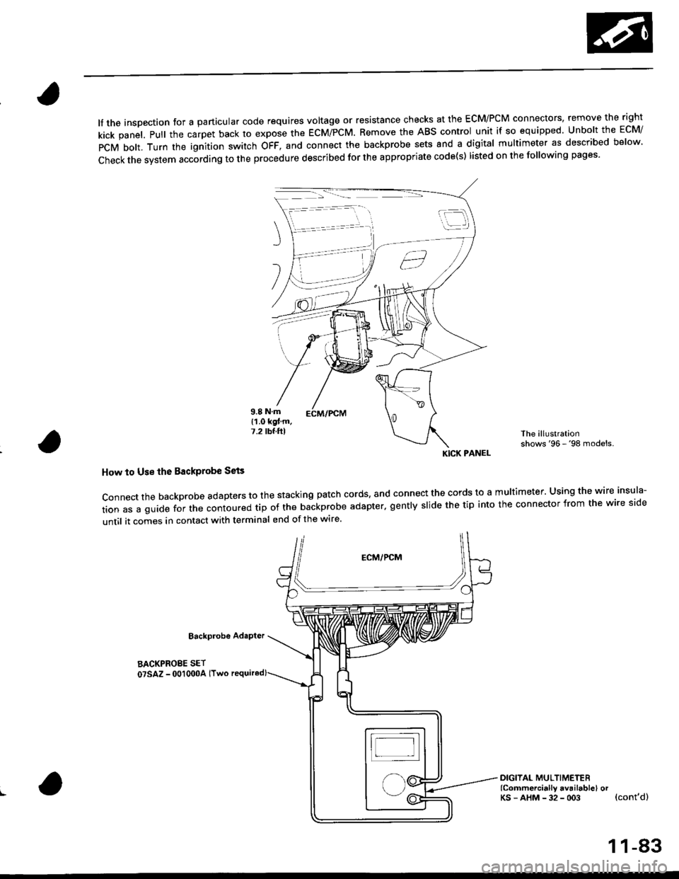
lf the inspection for a particular code requires voltage or resistance checks at the ECM/PCM connectors, remove the right
kick panel. Pull the carpet back to expose the ECM/PCM. Remove the ABS control unit if so equipped. unbolt the EcM/
PCM bolt. Turn the ignition switch oFF, and connect the backprobe sets and a digital multimeter as described below
check the system according to the procedure described for the appropriate code(s) listed on the following pages'
The illustrationshows '96 - '98 models.
How to Use lhe Backprobe Sets
connect the backprobe adapters to the stacking patch cords, and connect the cords to a multimeter. using the wire insula-
tion as a guide for the contoured trp of the backprobe adapter. gently slide the tip into the connector from the wire side
until it comes in contact with terminal end of the wire'
BackProbe
BACKPROEE SET
07SAZ - 001000A lTwo
DIGITAL MULTIMETER(Commercially avail.bleI orKs - AHM - 32 - oo3 (cont'd)
KICK PANEL
1 1-83
Page 357 of 2189
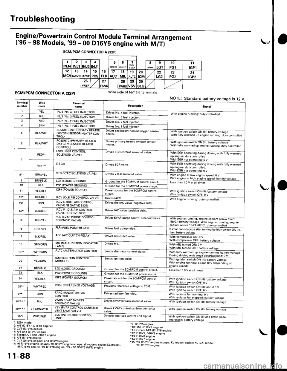
Troubleshooting
E n gine/P_o,weft ra in Control Module Term inal Arra n gement('96 - 98 Models, '99 - 00 Dl6yS engine with M/T)
-
ECM/PCM CONNECTOR A I32PI
1INJ62INJ3INJ21
INJl567I
LG110PGll1
IGPl12
ACV
131115
PCS
16
FLR17acc18MIL19ALTC20
tcM22PG221IGP2272A25
VSV30
SLU
ECM/PCM CONNECTOR A (32P)
'2: A./T (D16Y7, 016Y8 engine)13: CvT (D16Y5 enoin€)',4: A/T and D16y7 engine*5: Except A/T and D16Y7 €nsine'6r A/T (D16Y8 ensine)'7 Cw 1D16Y5 eng,nel and D16y8 ensrne'"'3:Bi..I?'Jt;".'e'.!ti.?i?l'""."T8"_";btfr
"fl
1-88
Wire side of female terminals
NOTE:Standard battery voltage12ts
'10i i,4/T (D16V5 engine)r11 Ex.ept M/l (D16V5 enqinelr12: 016Y5, D16YB enqine
r15:'97 016Y7 engine lcoupe: KL modet, sedan: KL (LXl modet),'98 D16Y7 engine
1
1
Sign.l
YELlNJ4 (No.4 FUEL INJECIOB)D ves No 4 ruel injector.Wilh engine runninq: ddly coniroted2BLUlNJ3 lNo. 3 FUEL TNJECTOBJDrives No. 3 lue Inteclor.38EDINJ2 (NO, 2 FUEI INJECTON)Drives No. 2 iuel njector.88NlNJl (No. 1 FUEL INJECTOB)Dives No. 1 ruelinjector.
5SO2SIITC (SECONDAFY HEATEDOXYGEN SENSOF HEATEF CONTFOL)
Orives secondary heated oxyqen sensorWith ignilion switch ON (lll: batery vo lageWith f!llywarmed up engine runninq:dLtv controled
6BLXAVHTPO2SHTC (PRIMAFY HEATEOOXYGEN SENSOR HEATERCONTROL)
Drives prihary healed oxygen sensorWith ignition switch ON ltt):baneryvottasewlhrdllywdrmedupcngne,Lnnrrq dury,orl.otred
FED{ESOL (EGF CONTRO!SOIENOIO VALVE)Drives EGF conlrolsoleno d vatve.Wilh EGR operating during drving wiih fu|y warmedup engrne: duty controttedWilh EGF nol opefating:O VE.EGRWith EGF operating du.ing driv og wilh iuty warmedup en9ine: dutycont.olted.With EGR not ooeralino; o V8*r/GFN/YELWS (VTEC SOLENOTD VALVE)Drives VTEC solenoid va veWilh eng ne at ow engine speed:O VWirh engine at h gh enqine speedr banery vohaae9BflN/BLKLG1 (LOGIC GROUND)Gro!nd lorthe €CM/PCM conlrotc rcuit.Lesslhan 1.0 V at a ttimest0ALKPG1 IPOWEF GFOUND)Ground ior rhe ECM/PCM power.tcuf.11YEVBLKIGPT iPOWEF SOUFCE)Power source forthe Ec[,l/PcM conlroWilh ignition swirch ON (tt): battery voltageWith gntron switch OFF: 0 VBLVBLUIACV (IDLE AIN CONTROL VALVE)Wilh engine r!nn ng: dlty contro ed13,.o8NIACV N lIDLE AI8 CONTFOLVALVE NEGATIVE SIOE)Drivesthe IAC valve {negalive side).
BLVBLUIACV P (IDLE AI8 CQNTROLVALVE POSITIVE SIDE)Orives IAC vaive (posilive side).
FEO/YELPCS (EVAP PURGE CONTFOTSOIENOIOVALVE)Drives EVAP pu.ge controtsolenoid vatve.Wilh engioe running, engin€ cootani betow 154,F'68'Cr bancry vohaSe w'ln ens nc runn,.o. eng,rc
GRN/YELFL8 (FUEL PU[4P FELAY)Orives fuelpump relay.0 V {or two secor os ahe' tJ n ng 'onir or \wnch ON ,,,,,
I7BLI(REOACC (A,/C CLUTCH RELAY)Drives A/C clutch relay.Wirh compressor ONr0 VWilh compressof OFF:banery votrage18GFN/ONNMIL (I\,lALFUNCTION INDICATOFWith MIL lLrned ON: 0 VWith illl turned OFF: banery volaqe19',AITC {AITERNAIOR CONIROL)se.ds ahernator controt signat.Wirh fully warmed.up engine ru.ntng: battery votlas€During drivins wnh smatl eteclricat toad: O V
20YEVGRNICM (IGNI'TION CONTROLMOOU!E)with ignltlon swilch ON (tl):b6n€ry vohageWilh ensine runnins: aboul t0 V (depending on
22BRN/BLKLG2 (LOGIC GAOUND)Ground for the ECM,/PCM conrrot ci'cu LLess than 1.0 V at a tt mes23BLKPG2 iPOWEA GROUND)Gro!nd lor the ECM/PCM power circuir.24YEUBLKlGP2 (POW€R SOUSCE)Power sou.ce lor the ECM/PCl, conrrolWnh ignilion swilch ON {it):battery vohageWilh ignilion switch OFF:0 V25*6WHT/FEDVSEF IREFEfl ENCE VOLTAGE)Provrdes reference voIaOe to TCM.With ignition switch ON (tt):abour 5 VWth gnition swltch OFF: O V21'1GFNFANC {RAOIATOR FANCONTFOL)Drives radialof fan ielay.With radialor fan f!nn nqr O VWilh radiato.tan stopped: batteryBL!2WBS (EVAP BYPASSSOLENOIO VALVE]Orives EVAP bypass sotenotd va !e.With ignirion swrrch ON (tt):barery vo rase
LT GRNA/VHTVSV (EVAP CONTFOTCANISTEFVENT SHUT VAIVE)Drives EVAP conlfot canisrer venl shulwnh ignirion sw'tch ON lr|l barery volaqe
WHT/NEDSLU (INTEFLOCK CONTFOLUNIT)Detects intenock conlrotLn t signalWhh ignition switch ON (tt)and brake pedadepf essed: battery vollage
Page 361 of 2189
Troubleshooting
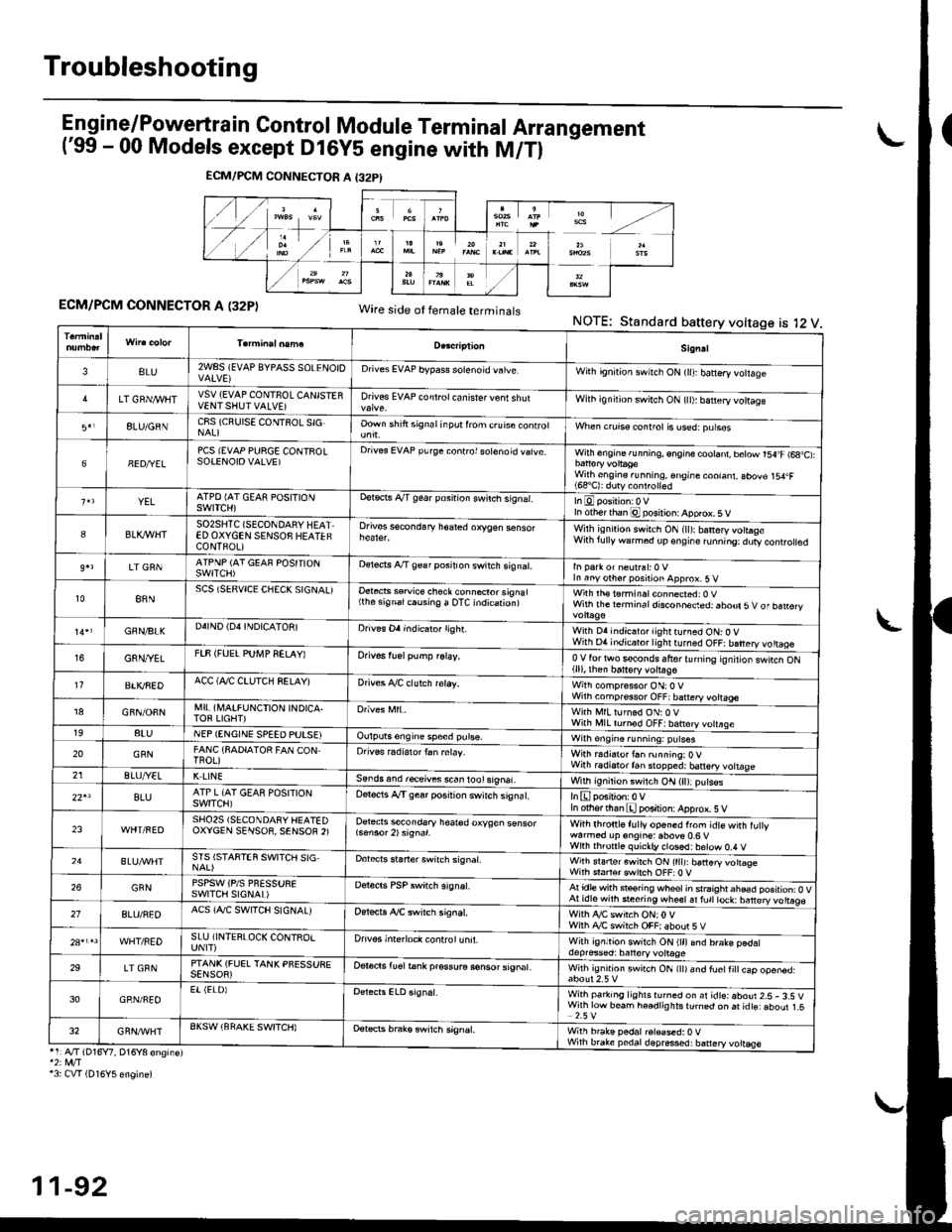
Engine/P_o,wertrain Control Module Terminal Arrangement('99 - 00 Models except Dl6Y5 engine with M/Tl
ECM/PCM CONNECTOR A (32P)Wire side ot temale terminalsNOTE:Standard battery voltage is l2 V
ECM/PCM CONNECTOR A I32PI
Sign!l
3BLU2WSS (EVAP 8YPAsS SOLENOIDDrives EVAP bypass solenoid vatve,With gn'tion swnch ON (lll banery votlage
LT GRN/I/VIITVSV {EVAP CONTNOL CANISTERVENTSHUTVALVE]Drives EVAP controt ca n isrer v€nt shutWilh ignilion switch ON {tl): b€ttery vottage
8LU/GNNC8S (CRUISE CONTSOL SIGOown shift signal inpot lrom c.uise conrrolWhen crurss control is used:purses
68ED/YELPCS {EVAP PURGE CONTROLSOTENOIOVALVE)Drives EVAP purge conrrol sotenoid vatve.With engine running, engine cootant, betow r54.F (6a,C):
With engine.unning, €ngine coolant, abov€ 154.F(68'C): duty conlrolled
YELATPD {AT GEAR POSITIONSWITCH)ootects A/T gear posnion swilch s,gnar.In otherthan @ posilion: Apprcx. 5 V
8BLK,IflHTSO2SHTC (SECONDARY HEATED OXYGEN SENSOS HEATEFCONTFOL)
Drives sscondary h€ared oxygen senso.Wilh isn,rion swirch ON (ll):banery votraseWith lully warm6d dp€ngire runn'ng:dury controled
LT GRNATPNP (AT GEAF POSITIONSWITCH)oereds A/T 9€a r position switch signat.In Parr or neulrsl:0 VIn anyother position approx.5 v
t088NSCS (SERVICE CHECK SIGNAL)Oetects ssruice check connecror signal(the signalcausing a OTC indication)with rh€ t6rminal connected: 0 vWith the rerm ina I disconneded: abour 5 V of ban€ry
GNN/BIKD4IND (D4INDICATON]Drives Oa indicaio. lighr.With D4 indicator lightturned ON: O VWith D4 indicator lightturned OFF: battery vo ttageG8N/YETFTF (FUEL PUI\,4P SELAY)Orivos tuel pump relay,0V for two s€conds lfrer turnrng rgnilior swtcn ON(ll), then batt€ry voltage11BTI(REDACC (Al/C CTUTCH SELAY)Drives A./C clutch reray.With compressor ON:O VWilh comp.ssor OFF; battery vottage18GFN/OFNMI! (A,IAIFUNCTION INDICA.TOF LIGHT)With MlLturned ON:0 VWith l\,llL tornod OFF|batrery votrsge198tuNEP (ENGINE SPEED PUTSEIOulputs6ngine speed pulse,Wilh engin6.unning: putses
20GFNFANC {SADIATOR FAN CONTnoL)Orives radiarortan relay.Wirh r.distor t6n running:OVWith radiatortan stopped: banery vottage21ELUA/ELK LINESends and r€ceives s.an lool signal.With ignition switch ON (ll):p!ts€s
22'lBLUATP L {AT GEAS POSITIONswtTcH)Oelocis A"/T gear posirion switch siSnat.In othfflhan E position: Apprcx. 5 V
23SHO25 (SECONOARY HEATEDOXYCEN SENSOR, SENSOF 2)Detects secondsry hoar€d oxygen sensorWith lhronle f! lly or'6ned from idte with fu ywarmod up engine: above 0.6 vWiih th.onl6 quickb, closd:below 0,4 V24STS ISTAFTEN SWITCH SIGDebcrs staner switch signat.Wirh srarterswitch ON (tttJ: batteryvottogeWith sraftsr cwirch OFF:0 V26GFNPSPSW iPlS PNESSURESWITCII SIGNAL)Derecrs PSP switch signat.Atidle with steoring wheolin srraightahead position: O VAt idl6with steering wheetal fult lock: barery vo ttags27BLU/REOACS (AJC SWITCH SIGNALJOer*ts ,ay'C swirch signat.Wiih ty'C switch ON;0VWilh Ay'C switch OFF|aboor 5VWHT/REDSLU iINTERLOCK CONTROIUNIT)Drivos interloct control unit.With ignltion switch ON (ll)and brake pedaldepresed: batlory volrage29LT GRNPTANK (FUEL TANK PFESSUEESENSOR)Oer6ds lu€l tank pr€ssura sonsor signat.Wilh ig.rrrd swirch ON rttr and fuetti
cap ooen6d.
30GRN/FEOEr (ELOIWith parking lighlsrurned on ar idteiaboui 2.5- 3.S VWirh low beam he€dlig hts turnqd on ai idts: aboul 1.52.5 V32GRN/'WHTAKSW (BFAKE SWITCH)Detets brak€ swrtch signEt,With brake pedal r6l€ased:0 VWhh brake pedaldepres*d: battery voltEse'1:A./T (D16Y7, D16Y8 engine)*2: rvt/T13: CVT (D16Y5 engine)
11-92
Page 681 of 2189

Description
The automatic transmission is a 3-element torque converter and a dual-shaft electronically controlled unit which provides
4 soeeds forward and 1 reverse.
Torque Convertel, Geats, and Clutches
The torque converter consists of a pump, turbine and stator, assembled in a single unit. They are connected to the engine
crankshaft so they turn together as a unit as the engine turns. Around the outside of the torque converter is a ring gear
which meshes with the starter pinion when the engine is being started. The entire torque converter assembly seryes as a
flywheel while transmiuing power to the transmission mainshaft.
The transmission has two parallel shafts: the mainshaft and the countershaft. The mainshaft is in Iine with the engine
crankshaft. The mainshaft includes the 1st, 2nd and 4th clutches, gears tor 2nd, 4th, reverse and lst (3rd gear is integral
with the mainshaft, while the reverse gear is integral with the 4th gear). The countershaft includes the 3rd clutch, and
gears for 3rd,2nd, 4th, reverse. 1st and park. The gears on the mainshaft are in constant mesh with those on the counter-
shaft. When certain combinations of gears in transmission are engaged by clutches. power is transmitted from the main-
shaft to the countershaft to provide E, ld, E, and E positions.
Electronic Control
The electronic control svstem consists of the Powertrain Control Module {PCM), sensors, a linear solenoid and four
solenojd valves. Shifting and lock-up are electronically controlled for comtonable driving under all conditions. The PCM is
located below the dashboard, under the front lower panel on the passenger's side
Hydraulic Control
The valve bodies include the main vatve body, the secondary valve body, the regulator valve body, the servo body and the
lock-up valve body through the respective separator plates, They are bolted on the torque converter housang
The main valve body contains the manual valve, the 1-2 shift valve. the 2nd orifice control valve, the CPB {Clutch Pressure
Back-up) valve, the modulator valve. the servo control valve, the relief valve, and ATF pump gears The secondary valve
body contains the 2-3 shift valve. the 3-4 shift valve, the 3-4 orifice control valve, the 4th exhaust valve and the CPC (Clutch
pressure Control) valve. The regulator valve body contains the pressure regulator valve, the torque converter check valve,
the cooler relief valve, and the lock-up control valve. The servo body contains the servo valve which is integrated with the
reverse shift fork, and the accumulators. The lock-up valve body contains the lock-up shift valve and the lock-up timing
valve. The linear solenoid and the shift control solenoid valve Ay'B are bolted on the outside of the transmission housing,
and the lock-up control solenoid valve Ay'B is bolted on the outside of the torque converter housing. Fluid from regulator
passes through the manual valve to the various control valves. The clutches receive fluid from their respective teed pipes
or internal hydraulic circuit.
Shift Control Mechanism
Input from various sensors located throughout the car determines which shift control solenoid valve the PCM will activate
Activating a shift control solenoid valve changes modulator pressure, causing a shift valve to move. This pressurizes a line
to one of the clutches, engaging that clutch and its corresponding gear, The shift control solenoid valves A and B are con-
trolled by the PCM.
Lock-up Mechanism
In ,Dt1 position, in 3rd and 4th. and in E position in 3rd, pressurized fluid is drained from the back of the torque converter
through a fluid passage, causing the lock-up piston to be held against the torque converter cover. As this takes place, the
mainshaft rotates at the same as the engine crankshaft. Together with hydraulic control, the PCM optimizes the timing of
the lock-up mechanism. The lock-up valves control the range of lock-up according to lock-up control solenoid valves A and
B, and linear solenoid. When lock-up control solenoid valves A and B activate, the modulator pressure changes The lock-
up control solenoid valves A and B and the linear solenoid are controlled by the PCM.
(cont'd)
14-3
Page 824 of 2189
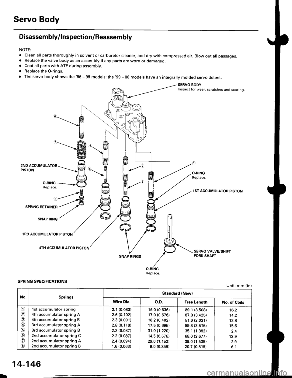
Servo Body
Disassembly/lnspection/Reassembly
NOTEI
. clean all parts thoroughly in solvent or carburetor cleaner, and dry with compressed air. Blow out all passages.. Replace the valve body as an assembly if any parts are worn or damaged.. Coat all parts with ATF during assembly.
. Replace the O-rings.
. The servo body shows the '96 - 98 models: the '99 - 00 models have an integrally molded servo detent.
SERVO BODYInspect for wear, scratches and scoring.
,______.- g
1l
v
"-------'g
ZruO lCCUr,irUr-nrOn ---rrr___-p
n\='l
3,ii11---------*5
^rrr4
I
O.RINGReplace.
3RO ACCUMULATOR PISTON
4TH ACCUMULATOR PISTON
SPRING SPECIFICATIONS
SNAP RINGS
1ST ACCUMULATOR PISTON
Unit: mm (in)
No.SpringsStandard {New)
Wire Dia.o.D.Free LengthNo. of Coils
o(a
@)
o
@
'I st accumulator spring
4th accumulator spring A
4th accumulator spring B
3rd accumulator spring A
3rd accumulator spring B
2nd accumulator spring C
2nd accumulator spring A
2nd accumulator spring B
2.1 (0.083)
2.6 (0.102)
2.3 (0.091)
2.8 (0.110)
2.210.0871
2.2 t0.0a7l
2.4 (0.094)'1.6 (0.063)
16.0 (0.636)
17.0 (0.676)
10.2lo.402J
17.5 (0.695)
31.0 11.220)
14.5 (0.576)
29.0 (1.152)
9.0 (0.358)
89.1 (3.s08)
87.0 (3.425)
51.6 (2.031)
89.3 (3.516)
35.1 (1.382)
68.012.677)
39.0 (1.535)
20.7 (0.815)
14.2
13.8
'13.9
L
14-146
Page 873 of 2189
Description
The Continuously Variable Transmission (CVT) is an electronically controlled automatic transmission with drive and driv
en Oullevs, and a steel belt. The CVT provides non stage speeds forward and one reverse. The entire unit is positioned in
line with the engine.
Transmission
Around the outside of the flywheel is a ring gear which meshes with the starter pinion when the engine is being staned.
The transmission has four parallel shafts: the input shaft, the drive pulley shaft. the driven pulley shaft, and the secondary
gear shaft. The input shaft is in line with the engine crankshaft. The drive pulley shaft and the driven pulley shaft consist of
movable and fixed face pulleys. Both pulleys are linked by the steel belt.
The input shaft includes the sun gear. The drive pulley shaft includes the forward clutch which mounts the carrier assem-
bly on the forward clutch drum. The carrier assembly includes the pinion gears which mesh with the sun gear and the ring
gear. The ring gear has a hub-mounted reverse brake disc.
The driven pulley shaft includes the start clutch and the secondary drive gear which is integral with the park gear' The sec-
ondary gear shaft is positioned between the secondary drive gear and the final driven gear. The secondary gear shaft
includes the secondary driven gear which serves to change the rotation direction. because the drive pulley shaft and the
driven oullev shaft rotate the same direction. When certain combinations of planetary gears in the transmission are
engaged by the clutches and the reverse brake, power is transmitted from the drive pulley shaft to the driven pulley shaft
to provide E, E, E, and El.
Electronic Control'96 - 98 Models:
The electronic control system consists of the Transmission Control Module (TCM), sensors, three linear solenoids, and a
inhibitor solenoid. Shifting is electronically controlled under all conditions'
The TCM is located below the dashboard, behind the kick panel on the driver's side.'99 - 00 Models:
The electronic control svstem consists of a Powertrain Control Module (PCM), sensors, three linear solenoids and an
inhibitor solenoid. Shifting is electronically controlled under all conditions. A Grade Logic Control System to control shift-
ing in E position while the vehicle is ascending or descending a slope.
The PCM is located below the dashboard, under the kick panel on the passenger's side.
Hydraulic Control
The lower valve body assembly includes the main valve body, the Pressure Low (PL) reguiator valve body, the shift valve
body, the start clutch control valve body, and the secondary valve body. They are positioned on the lower part of the
transmission housing.
The main valve body contains the Pressure High (PH) control valve, the lubrication valve, and the pitot regulator valve.
The secondary valve body contains the PH regulator valve, the clutch reducing valve, the start clutch valve accumulator,
and the shift inhibitor valve. The PL regulator valve body contains the PL regulator valve and the PH-PL control valve
which is ioined to the PH,PL control linear solenoid. The inhibitor solenoid valve is bolted on the PL regulator valve body.
The shift valve body contains the shift valve and the shift control valve. which is joined to the shift control linear solenoid.
The start clutch control valve body contains the start clutch control valve, which is joined to the start clutch control linear
solenoid. The linear solenoids and the inhibitor solenoid are controlled by the TCM or PCM. The manual valve body which
contains the manual valve and the reverse inhibitor valve, is bolted on the intermediate housing.
The ATF pump assembly is located on the transmission housing, and is linked with the input shaft by the sprockets and
the sprocket chain. The pulleys and the clutch receive fluid from their respective feed pipes, and the reverse brake receives
fluid from internal hydraulic circuit.
Shift Control Mechanism
Input from various sensors located throughout the vehicle determines which linear solenoid the TCM or PCM will activate.
Activating the shift control linear solenoid changes the shift control valve pressure, causing the shift valve to move. This
pressurizes the drive pulley pressure to the drive pulley and the driven pulley pressure to the driven pulley and changes
their effective pulley ratio. Activating the start clutch control linear solenoid moves the start clutch control valve. The start
clutch control valve uncovers the port, providing pressure to the start clutch to engage it(cont'd)
14-195
,!
Page 1076 of 2189
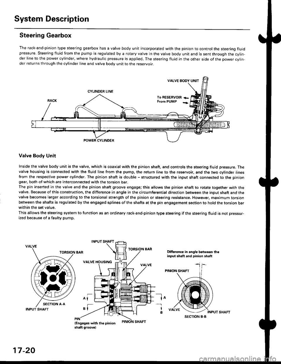
System Description
Steering Gearbox
The rack-and-pinion type steering gearbox has a valve body unit incorporated with the pinion to control the steering fluidpressure. Steering fluid from the pump is regulated by a rotary valve in the valve body unit and is sent through the cylin,der line to the power cylinder, where hydraulic pressure is applied. The steering fluid in the other side of the power cylin,der returns through the cylinder line and valve body unit to the reservoii.
VALVE EODY UNIT
CYLINDER LINE
To RESERVOm +-From PUMP -;
POWER CYLINDER
Valve Body Unit
Inside the valve body unit is the valve, which is coaxial with the pinion shaft, and controls the steering fluid pressure. Thevalve housing is connected with the fluid line from the pump, the return line to the reservoir, and the two cylinder linesfrom the respective power cylinder. The pinion shaft is double - structured with the input shaft connected to the piniongear, both of which are interconnected with the torsion bar.
The pin inserted in the valve and the pinion shaft groove engage; this allows the pinion shaft to rotate together with thevalve. Because of this construction, the difference in angle in the circumferential direction between the input shaft and thevalve becomes larger according to the torsional strength of the pinion or steering resistance. However, maximum torsionbetween the shafts is regulated by the engaged splines of the shafts at the pin engagement section to hold the torsion barwithin the set value,
This allows the steering system to function as an ordinary rack-and-pinion type steering if the steering fluid is not pressur-
ized because of a faulty pump,
VALVE
Difforence in angle botwoon theinput shaft and pinion shsft
PINION SHAFT
lo
INPUT SHAFT
-l
a
17-20
INPUT SHAFT
Page 1142 of 2189
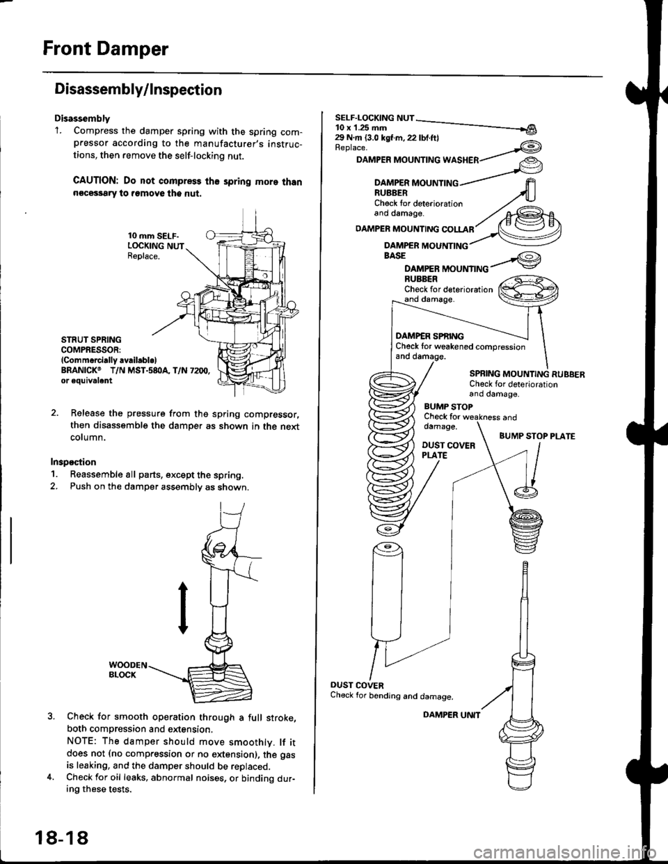
Front Damper
Disassembly/lnspection
Disassembly'1. Compress the damper spring with the spring com-pressor according to the manufacturer,s instruc-
tions, then remove the self-lockino nut.
CAUTION: Do not compress the spring more thann€cessary to remove the nut.
10 mm SELF-LOCKING NUTReplace.
STRUT SPRINGCOMPRESSOR:(Commerci.lly availabl.lBRANICKO T/N MST.s8I}A, T/N 7200,or eouivalent
Release the pressure from thg spring compressor,
then disassemble the damper as shown in the next
column.
Inspostion
1. Reassemble all parts, except the spring.
2. Push on th€ damper assembly as shown.
Check for smooth operation through a full stroke,
both compression and extension,
NOTE: The damper should move smoothlv. lf itdoes not (no compression or no extension), the gas
is leaking, and the damper should be replaced.Check for oil leaks, abnormal noises, or binding dur-ing these tests.
18-18
DAMPER UNIT
Replace.
DAMPER MOUNTING WASHER
BASE
DAMPER MOUNTINGBUBBERCheck for deteriorationand damage.
DAMP€R SPf,INGCheck tor weakened compressionand damage.
SPBING MOUNTING RUBBERCheck for deteriorationand damage,
BUMP STOPCheck fordamage.
DUST COVERPLATE
and
BUMP STOP PLATE
OUST COVERCheck for bending and damage.
Page 1149 of 2189
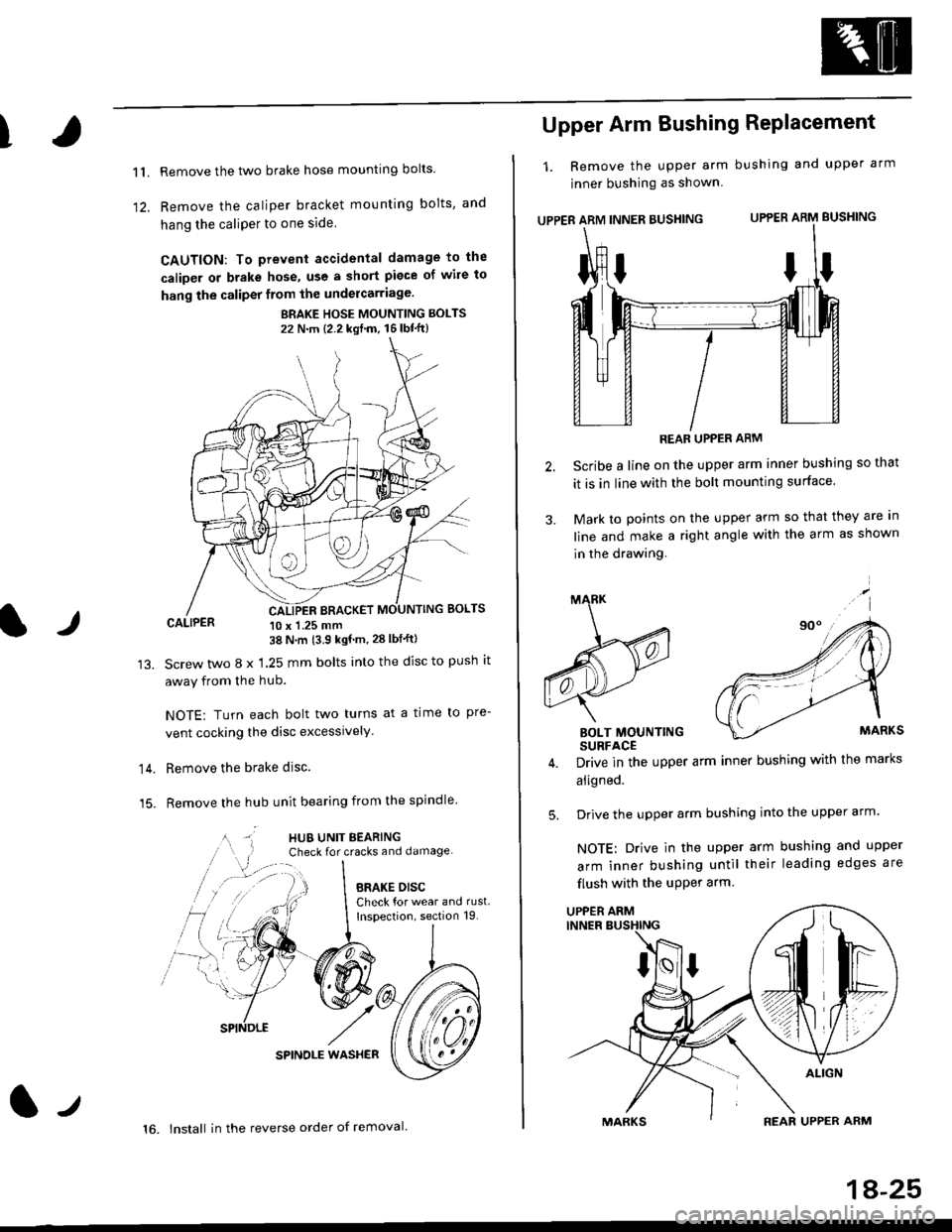
T
11.
1)
Remove the two brake hose mounting bolts
Remove the caliper b.acket mounting bolts, and
hang the caliPer to one side
CAUTION: To prevent accidental damage to the
caliper or brake hose, use a short piece of wile to
hang the caliper from the undercarriage.
BRAKE HOSE MOUNTING BOLTS
22 N'm {2.2 kgf'm, 16lbt"ft}
CALIPER 10 x 1.25 mm38 N'm (3.9 kgf'm, 28 lbf'ftl
Screw two 8 x 1.25 mm bolts into the disc to push it
away from the hub.
NOTE: Turn each bolt two turns at a time to pre-
vent cocking the disc excessively.
Remove the brake disc.
Remove the hub unit bearing from the spindle
SPINOLE WAS}IER
lr
14.
15.
lt
16. lnstall in the reverse order of removal.
1A-25
Upper Arm Bushing RePlacement
1. Remove the upper arm bushing and upper arm
jnner bushing as shown
UPPER ARM INNER BUSHING UPPER ARM BUSHING
REAR UPPER ARM
Scribe a line on the upper arm inner bushing so that
it is in line with the bolt mounting surface
Mark to points on the upper arm so that they are In
line and make a right angle with the arm as shown
in the drawing.
BOLT MOUNTINGSURFACE
Drive in the upper arm inner bushing with the marks
aligned.
Drive the upper arm bushing into the upper arm
NOTE: Drive in the upper arm bushing and upper
arm inner bushing until their leading edges are
flush with the uPPer arm
ttI
5.
UPPER ARM