no spark HONDA CIVIC 2000 6.G Workshop Manual
[x] Cancel search | Manufacturer: HONDA, Model Year: 2000, Model line: CIVIC, Model: HONDA CIVIC 2000 6.GPages: 2189, PDF Size: 69.39 MB
Page 58 of 2189
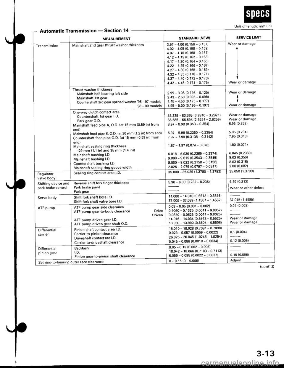
Automatic TnsmtsstonSection 14Un;t of length: mm {in)
r
MEASUREMENT
a
STANDARD INEW)SEBVICE LIMIT
TransmissionMainshaft 2nd gear thrust washer thickness
Thrust washer thicknessMainshaft ball bearing left sideMainshaft lst gear
Countershaft 3rd gear splined washer '96 97 models'98 - 00 models
One-way clutch contact area
Countershaft 1st gear LD.
Park gear O.D.Mainshaft feed pipe A, O.D. (at 15 mm (0.59 inlfrom
Mainshaft feed pipe B, O.D. (at 30 mm {1.2 in) from end)
Countershaft feed pipe O.D. lat 15 mm (0 59 in) from
eno)Mainshaft sealing ring thickness
129 mm 11.1 iniand 35 mm {1.4 in))
Mainshaft bushing l.D.
Mainshaft bushing LD.
Countershaft bushing LD.Mainshaft sealing ring goove width
3.97 4.00 10.156 - 0.157)4.02 - 4.05 (0.158 0.159)
4.07 - 4.10 (0.160 - 0.161)4.12 - 4.15 (0.162 0.163)
4.17 - 4.20 10.164 - 0.165)4.22 - 4.25 (0.166 - 0.167)4.27 - 4.30 (0.168-0.169)
4.32 - 4.35 (0.170 0.171)
4.37 - 4.40 10.172 - 0.173)
4.42 - 4.45 10.114 - 0.175l
1
I
+Wear or damage
2.95 - 3.05 {0.116 - 0.120)2.43 2.50 (0.096 - 0.098)4.45 - 4.50 (0.175 - 0.177i4.95 - 5.00 (0.195 0.197)
Wear or damage
+I
83.339 - 83.365 (3.2810 3.2821)
66.685 - 66.698 (2.6254 - 2.6259)
8.97 - 8.98 (0.353 - 0.354)
5.97 5.9810.2350 - 0.2354i7.97 - 7.98 (0.3138 - 0.3142)
1.87 - 1.97 {0.074 0.078)
6.0 r8 - 6.030 {0.2369 - 0.2374)
9.000 - 9.01s 10.3543-0.3549)8.000-8.022 (0.3150 - 0.3158)
2.025 - 2.015 l0.0197 -0.0417)
Wear or damageWear or darn age
8.95 (0.352J
5.95 (0.234)
7.95 (0.313)
1.80 (0.071)
6.045 (0.2380)
9.03 (0.356)
8.03 {0.316)2.08 (0.082)
Regulatorvalve body
Seating ring conlact area l.D.35.000 35.02511.3780 1.3782)35.050 (1.3799)
Shifting device andpark brake controlReverse shift fork Iinger thicknessPark brake pawl
Park gear
5.90 - 6.00 (0.232 - 0.236)5.40 (0.213)
lWear or other defect
Servo bodyShift fork shaft bore LD.
Shift fork shaft valve bore l.D.
14.000 - 14.010 (0.5512 - 0.5516)
37.000 - 37.039 (1.4567 - 1.4582)37.045 (1.4585)
ATF pumpATF pump gear side clearanceATF pump gear-to-body clearance DriveDaiven
ATF pump driven gear LD.ATF pump driven gear shaft O.D
0.03 -0.05 {0.001 - 0.002)0.1050 - 0.1325 (0.0041 - 0.0052)
0.0350 - 0.0625 (0.0014 - 0.0025)14.0'�|6 - 14.034 {0.5518 - 0.5525i13.980 13.990 (0.5504 0.5508)
0.07 (0.003)
Differentialcarrier
Pinion shaft contact area LD.
Carrier to'pinion clearanceDriveshaft contact are LD.
Carrier to-driveshaft clearance
18.010 18.028 {0.7091 0.7098)
0.023 - 0.057 (0.0009 -0.0022)
26.025 * 26.045 11.0246 1.0254)
0.045 - 0.086 (0.0018 - 0.0034)
0.1 {0.004)
0.12 {0.005)
Differentialprnron gearBacklasht.D.Pinion gear to-pinion shaft clearance
0.05 - 0.15 {0.002 - 0.006)18.042 - 18.066 (0.7103 - 0.7113i0.055 - 0.095 (0.0022 - 0.0037)ffi.oour
Set ring-to bearing outer race clearance0 - 0.15 (0 0.006)Adjust
(cont'd)
3-13
Page 64 of 2189
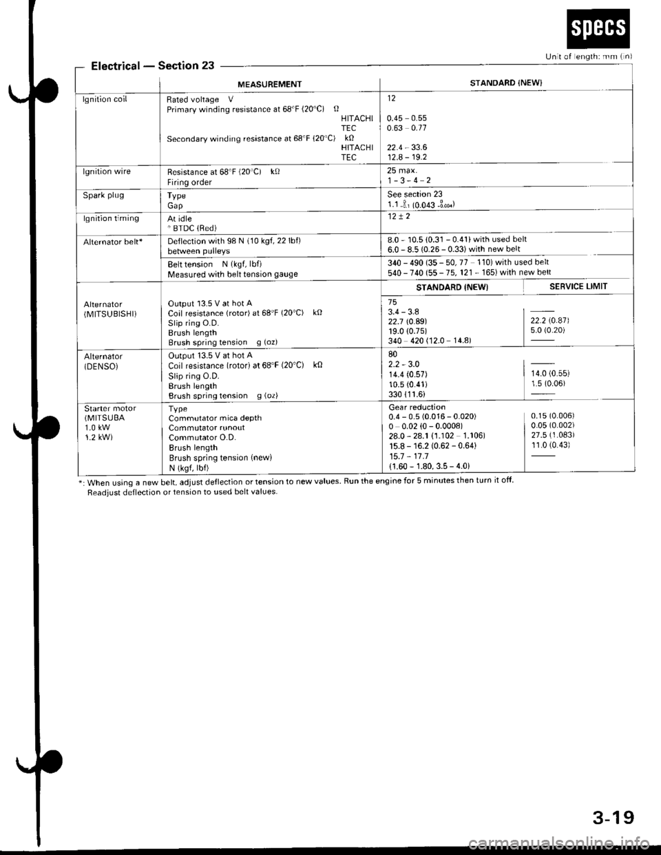
ElectricalSection 23
*: When using a new belt, adjust deflection or tension to new values. Run the engine for 5 minutes then turn it off
Readiust deflection or tension to used belt values
Unit of englh: mm {n)
MEASUREMENTSTANDARD {NEW}
lgnition coilRated voltage VPrimary winding resistance at 68'F (20'C) oHITACHITEC
Secondary winding resastance at 68'F 120"C) kOHITACHITEC
12
0.45 0.550.63 0.11
22.4 - 33.612.A - 19.2
lgnition wireResistance at 68'F (20'C) kf)
Firing order
25 max.1-3-4 2
Spark plugTypeGap
See section 231.1 3, (o.o€ -3*.)
lgnition timingAt idle' BTDC lRed)
Alternator belt+Deflection with 98 N (10 kgf,22lbf)between pulleys8.0 - 10.5 {0.31 - 0.41} with used belt
6.0 - 8.5 {0.26- 0.33)with new belt
Belt tension N (kgf, lbf)
Measured with belt tension gauge340 - 490 (35 - 50, 77 110) with used belt
540 - 740 (55 - 75, 121. 165)whh newbert
(MITSUBISHI)Output l3.5 V at hot ACoal resistance (rotor) at 68'F (20"C) kO
Slip rins O.D.Brush lengthBrush spring tension g (oz)
STANDARD INEWI SERVICE LIMIT
753.4-3.8 I -
Z2.j \0.A9) 22.2 \0.47)19.0 (0.75) 5.0 (0.20)
340 420 (12.0 14.8)
Alternator(DENSOiOutput '13.5 V at hot A
Coil resistance (rotor) at 68'F (20'C) k0
Slip ring O.D.Erush lengthBrush spring tension g (oz)
802.2 - 3.014.4 (0.57) | 14.0 (0.55)
10.5 (0.41) 1.5 (0.06)
330 {11.6)
Starter(MITSUEA
1.0 kw1.2 kW)
TvpeCommutator mica depthCommutator runoutCommutator O.D.Brush lengthBrush spring tension (new)
N (ksf, lbf)
Gear reduction0.4 - 0.5 (0.016 - 0.020) 0.15(0.006)
o o.o2 (o - 0.000e) | o.o5 (o.oo2)
28.0-28.1 (1.102 1.106) | 27.5(1.083)
15.8 - 16.2 10.62 - 0.64) 11.0 (0.43)
15.7 - 11 .1
{1.60 - 1.80, 3.5 - 4.0i
3-19
Page 98 of 2189
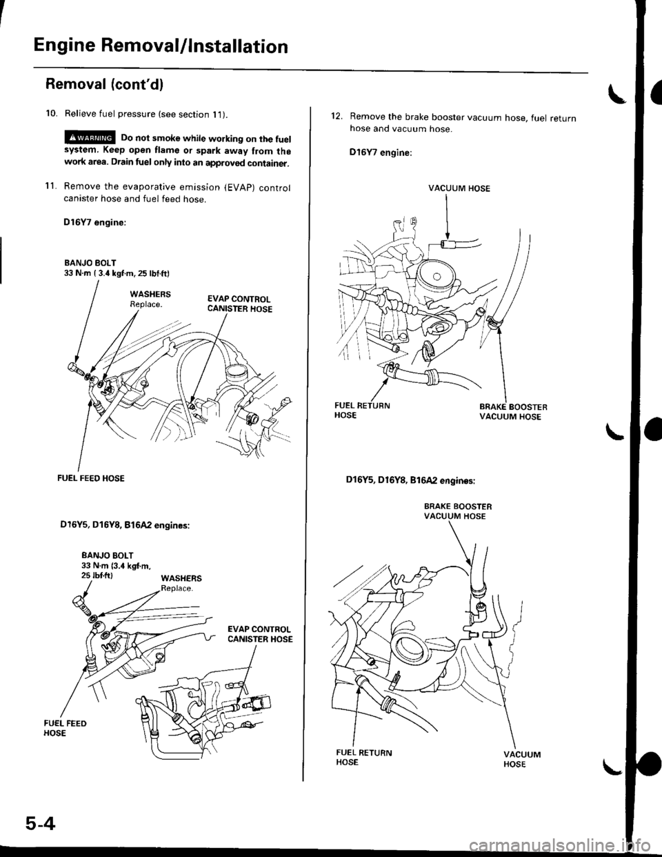
Engine Removal/lnstallation
Removal (cont'dl
10. Relieve fuel pressure (see section l1).
!@ Do not smoke while working on the fuelsystem, Keep open flame or spark away from thewolk area. Drain fuel only inlo an approved container.
11. Remove the evaporative emission (EVAP) controlcanister hose and fuel feed hose.
D16Y7 engine:
BANJO BOLT33 N m ( 3.it lgt m, 25 lbt.ft)
FUEI- FEED HOSE
D16Y5, D16Y8, Bt642 engines:
5-4
I
12. Remove the brake
hose and vacuum
D16Y7 engine:
booster vacuum hose, fuel returnhose.
VACUUM HOSE
Dl6Y5, D16Y8, Bl642 enginos:
BRAKE BOOSTERVACUUM HOSE
Page 125 of 2189
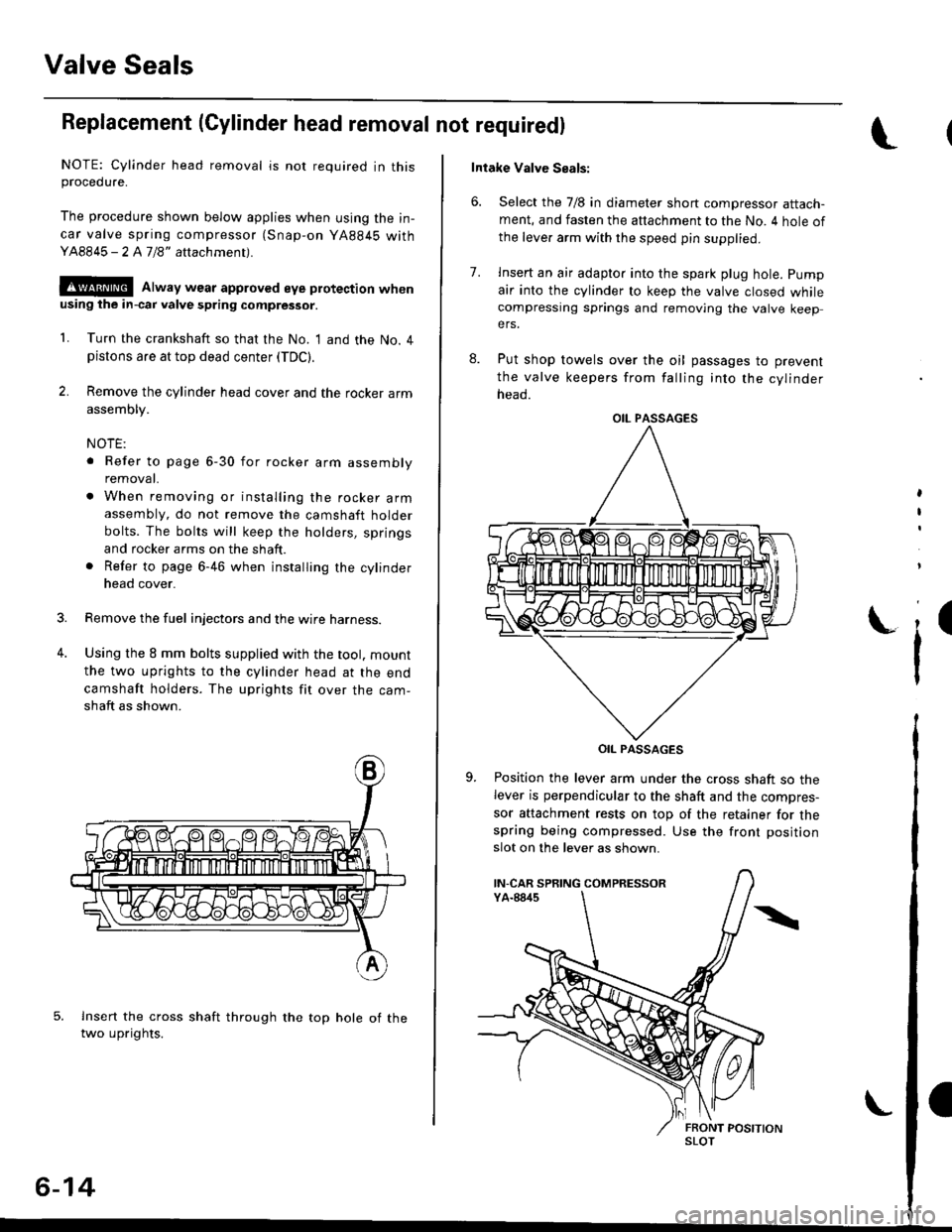
Valve Seals
Replacement (Cylinder head removal not requiredl
NOTE: Cylinder head removal is not required in thisprocedure.
The procedure shown below applies when using the in-
car valve spring compressor (Snap-on YA884S withY48845 - 2 A7/8" attachment).
!@@ Alway wear approved eye protection whenusing ihe in-cai valve spring compressor.
1. Turn the crankshaft so that the No. I and the No. 4pistons are at top dead center (TDC).
2. Remove the cylinder head cover and the rocker arm
assembly.
NOTE:
. Refer to page 6-30 for rocker arm assembly
removat.
. When removing or installing the rocker armassembly, do not remove the camshaft holder
bolts. The bolts will keep the holders, springs
and rocker arms on the shaft.
. Refer to page 6-46 when installing the cylinder
head cover.
Remove the fuel injectors and the wire harness.
Using the 8 mm bolts supplied with the tool. mount
the two uprights to the cylinder head at the end
camshaft holders. The uprights fit over the cam-
shaft as shown.
lnsert the cross shaft through the top hole of thetwo uprights.
3.
4.
6-14
Intake Valve Seals:
6. Select the 7/8 in diameter short compressor attach-ment, and fasten the attachment to the No. 4 hole of
the leve. arm with the speed pin supplied.
8.
7.lnsert an air adapto. into the spark plug hole. pump
air into the cylinder to keep the valve closed whilecompressing springs and removing the valve keepers.
Put shop towels over the oil passages to prevent
the valve keepers from falling into the cylinder
neao.
OIL PASSAGES
Position the lever arm under the cross shaft so thelever is perpendicular to the shaft and the compres-
sor attachment rests on top of the retainer for thespring being compressed. Use the front position
slot on the lever as shown.
,
I
i'
OIL PASSAGES
IN-CAR SPRING COMPRESSOR
SLOT
Page 140 of 2189
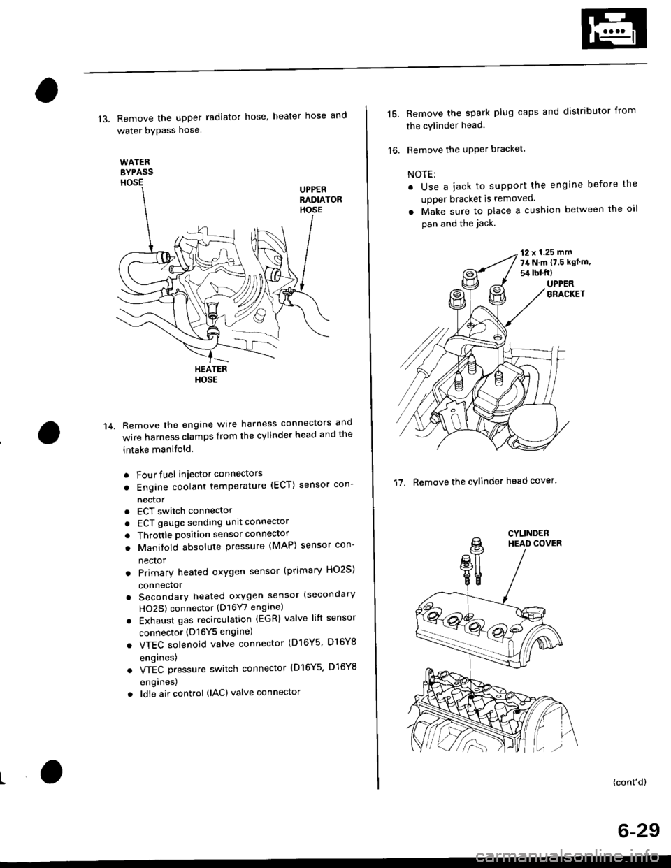
13. Remove the upper radiator hose' heater hose and
water bYPass hose
WATEREYPASSHOSEUPPERRADIATORHOSE
14.
HEATERHOSE
Remove the engine wire harness connectors and
wire harness clamps from the cylinder head and the
intake manifold.
o Four fuel injector connectors
. Engine coolant temperature (ECT) sensor con-
nector
a
a
a
ECT switch connector
ECT gauge sending unit connector
Throttle position sensor connector
Manitold absolute pressure (MAP) sensor con-
nector
Primary heated oxygen sensor (primary HO2S)
connector
Secondary heated oxygen sensor (secondary
HO2S) connector (D16Y7 engine)
Exhaust gas recirculation (EGR) valve lift sensor
connector (D16Y5 engine)
. VTEC solenoid valve connector (Dl6Y5, D16Y8
engrnes)
. VTEC pressure switch connector (D16Y5. D16Y8
engrnes,
. ldle air control (lAC) valve connector
15.Remove the spark plug caps and distributor from
the cylinder head.
Remove the uPPer bracket.
NOTE:
. Use a jack to support the engine before the
upper bracket is removed.
. Make sure to place a cushion between the oil
pan and the jack.
12 x 1.25 mm
74 N.m {7.5 kgf m.
sil lbl.ftl
UPPERBRACKET
'17. Remove the cylinder head cover'
CYLINDERHEAD COVER
(cont'd)
6-29
Page 158 of 2189
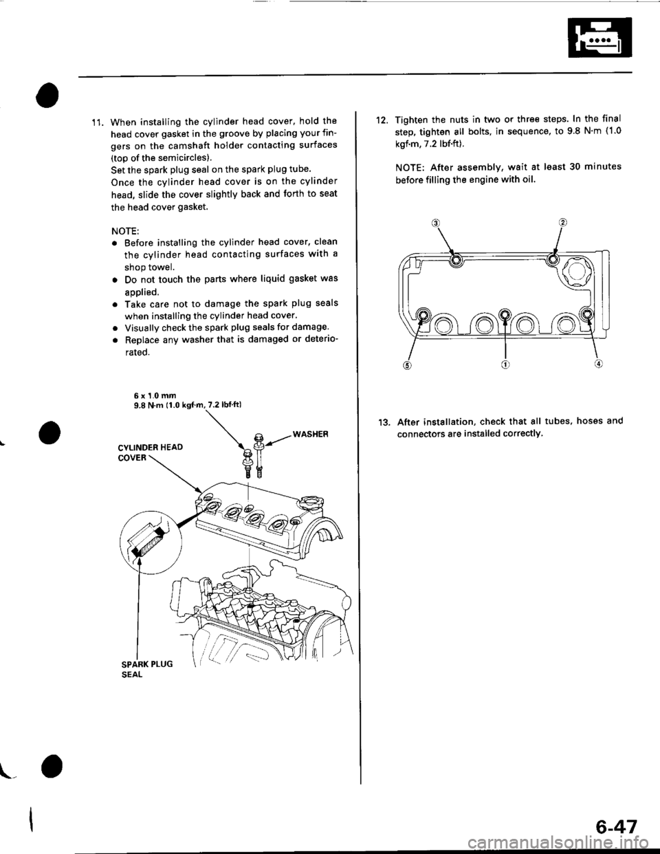
11. When installing the cylinder head cover, hold the
head cover gasket in the groove by placing your fin-
gers on the camshaft holder contacting surfaces
(top of the semicircles)
Set the spark plug seal on the spark plug tube.
Once the cylinder head cover is on the cylinder
head, slide the cover slightly back and forth to seat
the head cover gasket.
NOTE:
. Before installing the cylinder head cover, clean
the cylinder head contacting surfaces with a
shop towel.
. Do not touch the parts where liquid gasket was
aDolied.
. Take care not to damage the spark plug seals
when installing the cylinder head cover,
. Visually check the spark plug seals for damage.
. Replace any washer that is damaged or deterio-
rated.
6x1.0mm9.8 N.m 11.0 ksf.m,7.2lbf ftl
\g-----*o""t'Ptl
veEE
\_
6-47
12. Tighten the nuts in two or thre€ steps. In the final
step, tighten all bolts, in sequence, to 9 8 N'm (1.0
kgf.m, 7.2 lbf.ft).
NOTE: After assemblv, wait at least 30 minutes
before filling the engine with oil
After installation, check that all tubes, hosss and
connectors are installed correctlY
1?
Page 178 of 2189
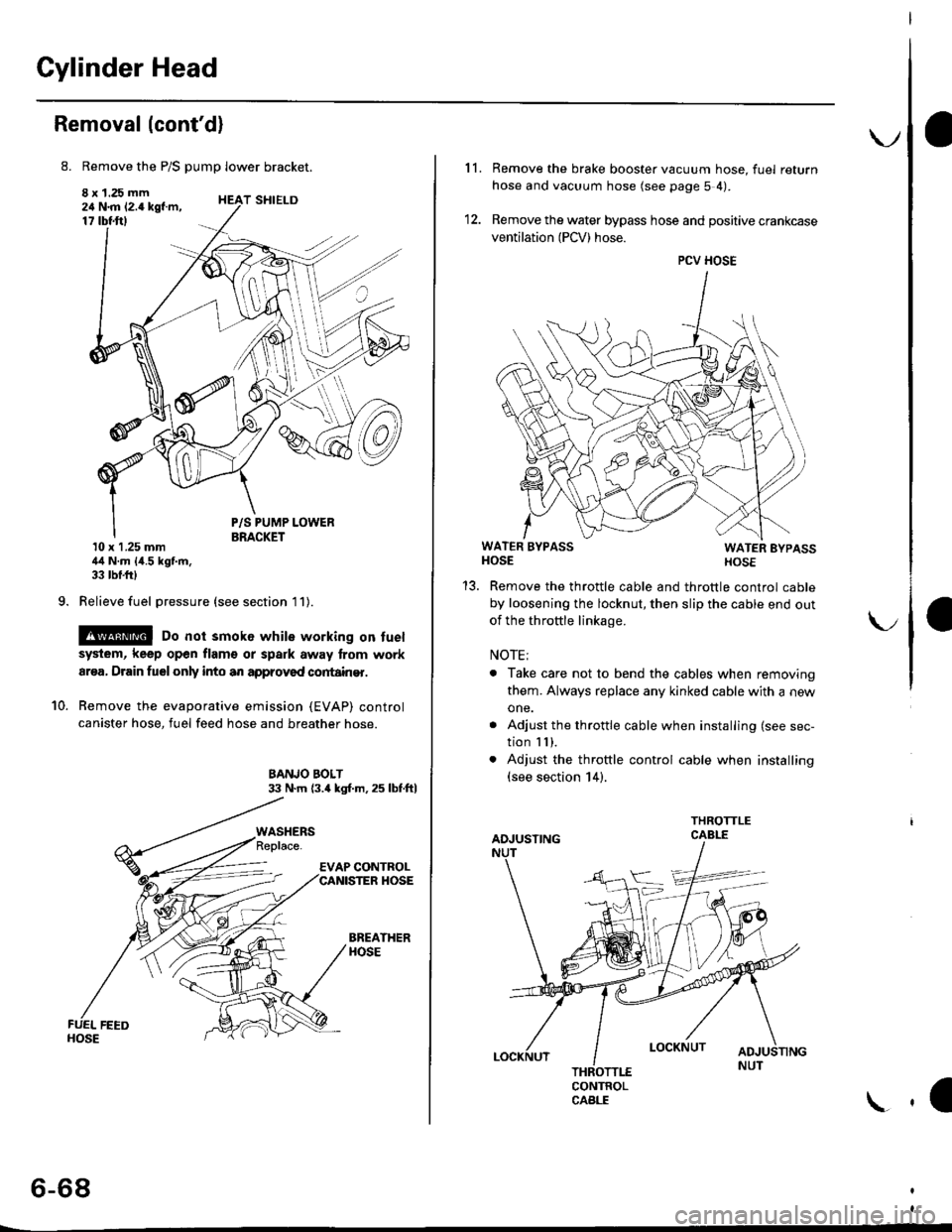
Cylinder Head
Removal (cont'd)
8. Remove the P/S pump lower bracket.
8 x 1.25 mm24 N.m 12.4 kgf.m,17 tbtftl
9.
T SHIELD
10.
P/S PUMP LOWERBRACKET10 x 1.25 mm44 N.m {4.5 kgf.m,33 tbf.frl
Relieve fuel pressure (see section l1).
@ Do not smok6 while working on fuel
system, keep open flam€ or spark away lrom work
ar€a, Drain fuelonly into an approved cortain€r.
Remove the evaporative emission (EVAP) control
canister hose, fuel feed hose and breather hose.
BANJO BOLT33 N.m (3.4 kgl.m.25 lbf.ftl
BREATHERHOSE
WASHERS
6-68
\.
11. Remove the brake booster vacuum hose, fuel return
hose and vacuum hose (see page 5 4).
12. Remove the water bypass hose and positive crankcase
ventilation (PCV) hose.
WATER BYPASSHOSEWATER EYPASSHOSE
Remove the throttle cable and throttle control cable
by loosening the locknut, then slip the cable end out
of the throftle linkage.
NOTE;
. Take care not to bend the cables when removing
them. Always replace any kinked cable with a new
one.
. Adjust the throttle cable when installing (see sec-
tion I I ),. Adjust the throttle control cable when installing(see section 14).
CONTROLCABLE
1a
PCV HOSE
Page 179 of 2189
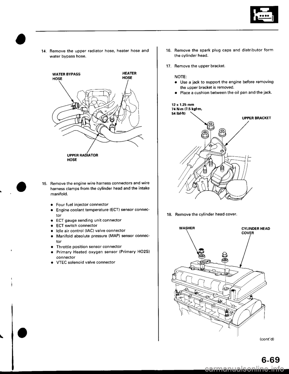
WATER BYPASS
HOSE
14. Remove the upper radiator hose, heater hose and
water bvpass hose.
HEATER
Remove the engine wire harness connectors and wlre
harness clamps from the cylinder head and the intake
manifold.
Four fuel injector connector
Engine coolant temperature (ECT) sensor connec-
tor
ECT gauge sending unit connector
ECT switch connector
ldle air control (lAC) valve connector
Manifold absolute pressure (MAP) sensor connec-
tor
Throttle position sensor connector
Primary Heated oxygen sensor (Primary HO2S)
connecror
VTEC solenoid valve connector
15.
a
a
a
a
a
\
16.
17.
Remove the spark plug caps and distributor form
the cylinder head.
Remove the upper bracket.
NOTE:
. Use a jack to support the engine before removing
the upp€r bracket is removed.
. Place a cushion between the oil panandthejack.
12 x 1.25 fin74 N.m 17.5 kgtm,
UPPER BRACKET
18. Remove the cylinder head cover.
{cont'd)
6-69
Page 435 of 2189
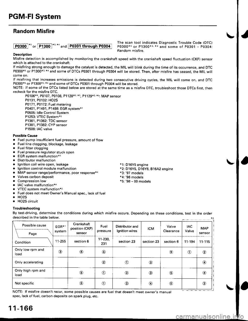
PGM-FI System
Random Misfire
lFoioo l*u o, [FTioo l*' *' and
The scan tool indicates Diagnostic Trouble Code (DTC)
P0300*5 or P1300*3 *1 and some of P0301 - P0304:Random misfire.Description
Misfire detection is accomplished by monitoring the crankshaft speed with the crankshaft speed fluctuation (CKF) sensorwhich is attached to the crankshaft.
lf misfiring strong enough to damage the catalyst is detected. the MIL will blink during the time of its occurrence, and DTCP0300*5 or P1300*3'*' and some of DTCs P0301 through P0304 will be stored. Then, after misfire has ceased, the MIL willcome on.
lf misfiring that increases emissions is detected during two consecutive driving cycles, the MIL will come on, and DTCP0300*5 or P1300*3 *a and some of DTCS P0301 through P0304 will be stored.NOTE: lf some of the DTCS listed below are stored at the same time as a misfire DTC. troubleshoot those DTCS first, thenrecheck for the misfire DTC.
P0106*4. P0107. P0108, P1128*3 *5, Pl129*3 *5; MAP sensorP0131. P0132: HO2S
P0171, P0112i Fuel metering
P0401, P 1491, P1498: EGR svstem*1P0505: ldle Control SystemP1253: VTEC System*,P1361, P1362: TDC sensorP1381, Pl382: CYP sensorP1508: IAC valve
Possible Cause. Fuel pump insufficient fuel pressure, amount of flow. Fuel line clogging, blockage, leakage. Fuel filter clogging. Fuel pressure regulator stuck open. EGR system malfunction*1. Distributormalfunction. lgnition coil wire open. leakage *l: D16Y5 engine. lgnition control module malfunction *2: D16Y5, D16Y8, Bt6A2 engine. MAP sensor range/performance, poor response*r *3: '97 models. Valves carbon deposit *4;'96 models. Compression low *5: '98 - 00 models. IAC valve malfunctionr.. VTEC system malfunction*,. Fuel does not meet Owner's Manual spec., lackoffuel. HO2S. HO2S circuit
Troubleshooting
By test-driving, determine the conditions during which misfire occurs, Depending on these conditions, test in the orderdescribed in the table below.
Possible
- --^ ---
rage
causeEGR*1
system
Crankshaft
position (CKP)
sensor
Fuel
pressure
Distributor and
lgnition wirestcMClearance
tAc
ValveMAP
sensor
section 611-230,
231section 23section 23section 611-19411
Only low rpm and
loado@@oo
Only accelerating@o@@
Only high rpm and
toaooo@
Not specificoo@
NOTE: lf misfire doesn't recur, some possible causes are fuel that doesn't meet owne/s manualspec, lack of fuel, carbon deposits on spark plug, etc.
1 1-1 66
I
P0304
Page 436 of 2189
I
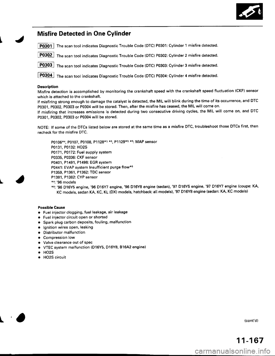
Misfire Detected in One Cylinder
P0301 | The scan tool indicates Diagnostic Trouble Code (DTC) P0301: Cylinder 1 misfire detected.
[F03O2l 16"""untool indicates Diagnostic Trouble code (DTc) P0302: Cylinder2 misfire detected.
[FO3Ofl 16" ".un toot indicates Diagnostic Troubte Code (DTC) P0303; Cylinder 3 misfire detected.
I P0304 I ths..rr tool indicates Diagnostic Trouble Code (DTC) PO3O4: Cylinder 4 misfire detected.
D€scription
lMisfire detection is accomplished by monitoring the crankshaft speed with the crankshaft speed fluctuation (CKF) sensor
which is attached to the crankshaft,
lf misfiring strong enough to damage the catalyst is detected, the MIL will blink during the time of its occurrence, and DTC
PO3O1, P0302, PO3O3 or P0304 will be stored. Then, after the misfire has ceased, the MIL will come on.
lf misfiring that increases emissions is detected during two consecutive driving cyclss, the MIL will come on, and DTC
P0301, P0302, P0303 or P0304 will be stored.
NOTE: lf some of the DTCS listed below are stored at the same time as a misfire DTC, troubleshoot those DTCS first, then
recheck for the misfire DTC.
PO106*1, P0107, P0108. P1128*3'*5, P1129*3'*5: MAP sensor
P0131, P0132: HO2S
P0171, P0172iFuel suppiy system
P0335, P0336: CKF sensor
P0401. P1491, P1498: EGR system
P0441: EVAP system Insufficient purge flow*6
Pl359. P1361. Pl362: TDC sensor
P1381. Pl382: CYP sensor*o: '96 models*6: '96 D16Y5 engine,'96 D16Y/ engine,'96 D16Y8 engine {sedan),'97 D16Y5 engine,'97 D16\4, engine (coupe: KA,
KC models, sedan KA. KC, KL (DX) models, hatchback:all models),'97 D16Y8 engine (sedan: KA, KC models)
Possible Cause
. Fuel injector clogging, fuel leakage, air leakage
. Fuel injector circuit open or shorted
. Spark plug carbon deposits, fouling, malfunction
. lgnition wires open. leaking
. Distributor malfunction
. ComDression low
. Valve clearance out of spec
. VTEC system malfunction (D16Y5, D16Y8. 81642 engine)
. HO2S
. HO2S circuit
(cont'd)
11-167
r'a