ECU HONDA CIVIC 2002 7.G Owners Manual
[x] Cancel search | Manufacturer: HONDA, Model Year: 2002, Model line: CIVIC, Model: HONDA CIVIC 2002 7.GPages: 1139, PDF Size: 28.19 MB
Page 761 of 1139
2.
5.
Fuel Fill Door Opener Cable Replacement
SRS components are located in this area. Review the SRS component locations (see page 23-13) and the precautions
and procedures (see page 23-14) in the SRS section before performing repairs or service.
NOTE;. Put on gloves to protect your hands.. Take care notto scratch the body and related parts.
1. Remove these items from the left side of the vehicle:
. Door silltrim {see page 20-50). Rear side trim panel (see page 20-51)
Pullthe carpet back as necessary (see page 20-55).
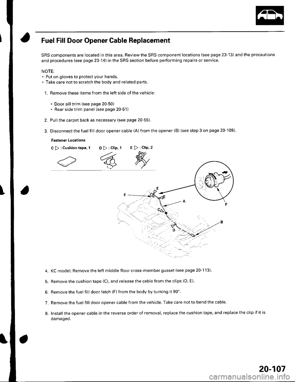
Disconnect the fuel fill door opener cable (A) from the opener (B) (see step 3 on page 20-109).
Fastener Locations
C >:Cushiontape, 1 D >: Clip, 1E > : Clip, 2
4. KCmodel: Removethe left middle floor cross-member gusset (see page 20-113).
5. Remove the cushion tape {C), and release the cable from the clips (D, E).
6. Removethefuel fill doorlatch (F)fromthe bodybyturning it90'.
7. Remove the fuel fill door opener cable from the vehicle. Take care not to bend the cable
8. Install theopenercableinthereverseorderofremoval,replacethecushiontape,andreplacetheclipifitis
oamageo.
20-107
Page 762 of 1139
Openers
Hood Latch Replacement
NOTE:. Put on gloves to protect your hands.. Take care not to scratch the body.
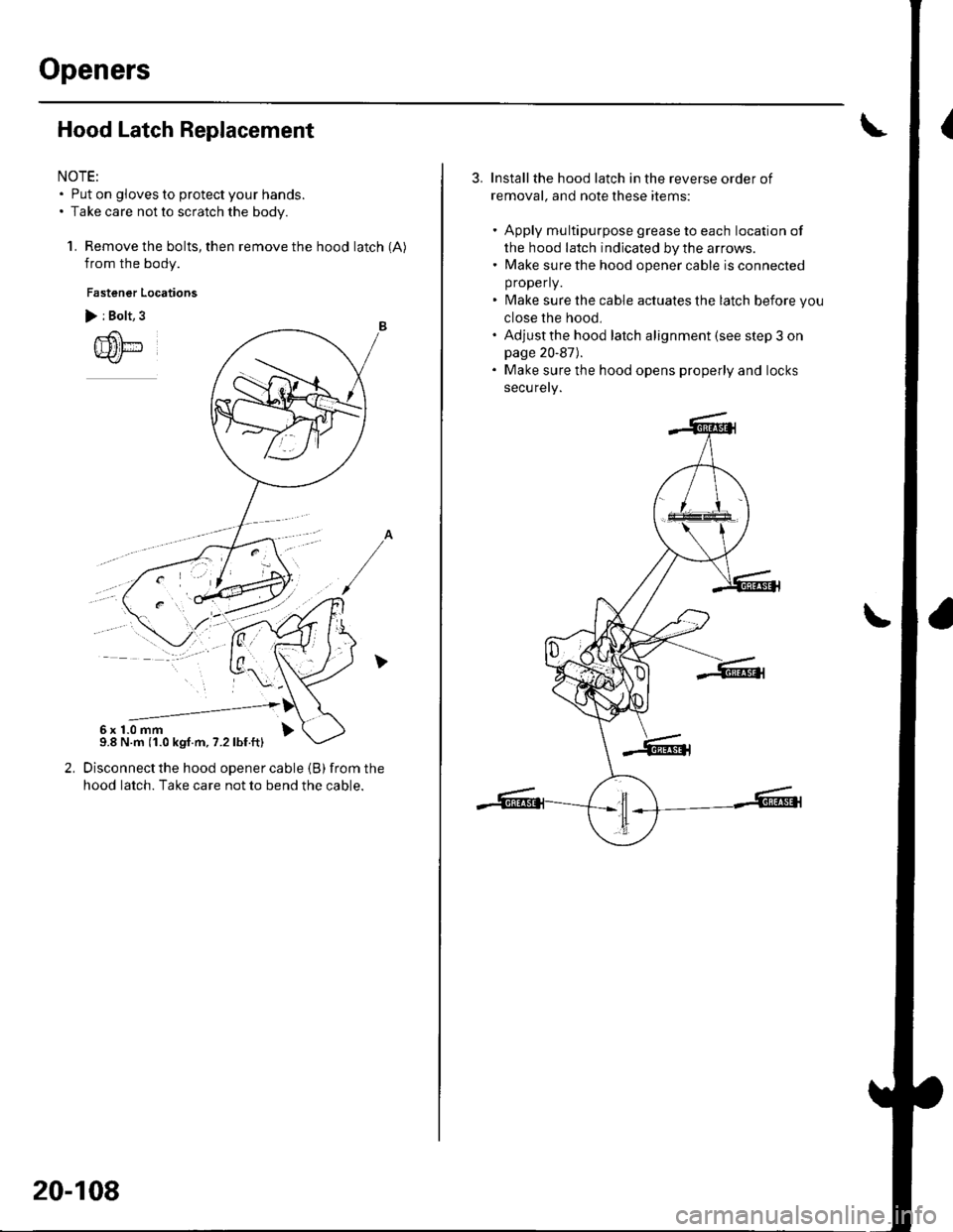
1. Remove the bolts, then remove the hood latch (A)
from the body.
Fastener Locations
> i Bolt, 3
Disconnect the hood opener cable (B) from the
hood latch. Take care not to bend the cable.
--------------'6x1.0mm9.8 N.m (1.0 kgf.m, 7.2lbf.ft)
20-108
Installthe hood latch in the reverse order of
removal, and note these items:
. Apply multipurpose grease to each location of
the hood latch indicated by the arrows.. Make sure the hood opener cable is connected
properly.
. Make sure the cable actuates the latch before you
close the hood,. Adjustthe hood latch alignment (see step 3 onpage 20-87).. Make sure the hood opens properly and locks
securely.
Page 763 of 1139
Fuel Fill Door Opener Replacement
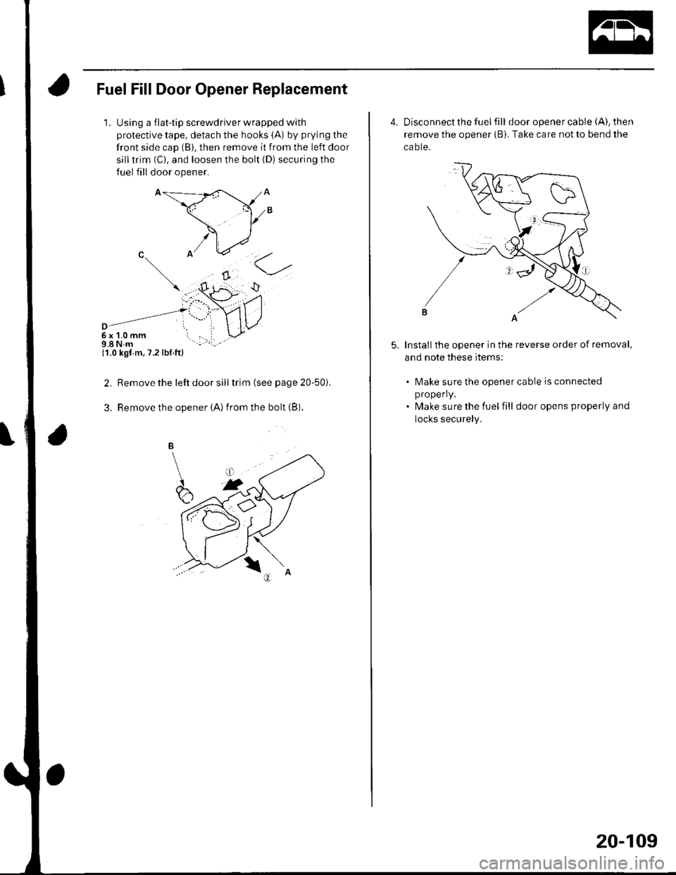
1.Using a flat-tip screwdriver wrapped with
protective tape, detach the hooks (A) by prying the
front side cap (B), then remove it from the left door
silltrim (C), and loosen the bolt (D) securing the
fuel fill door opener.
6x1.0mm9.8 N.m11.0 kgf m,7.2 lbf.ft)
Remove the left door sill trim (see page 20-50i.
Remove the opener (Alfrom the bolt {B).
2.
3.
4. Disconnect the fuel fill door opener cable (A), then
remove the opener iB). Take care not to bend the
ca o te.
Installthe opener in the reverse order of removal,
and note these items:
5.
lMake sure the opener cable is connected
properly.
lvlake sure the fuel fill door opens properly and
locks securely.
20-109
Page 764 of 1139
Openers
Hatch Handle Replacement
NOTE: Put on gloves to protect your hands.
1. Remove these items:
. Hatch lower trim panel (see page 20-53). Rear license trim panel (see page 20-98)
2. Remove the rear window wiper motor (see page
22-1461.
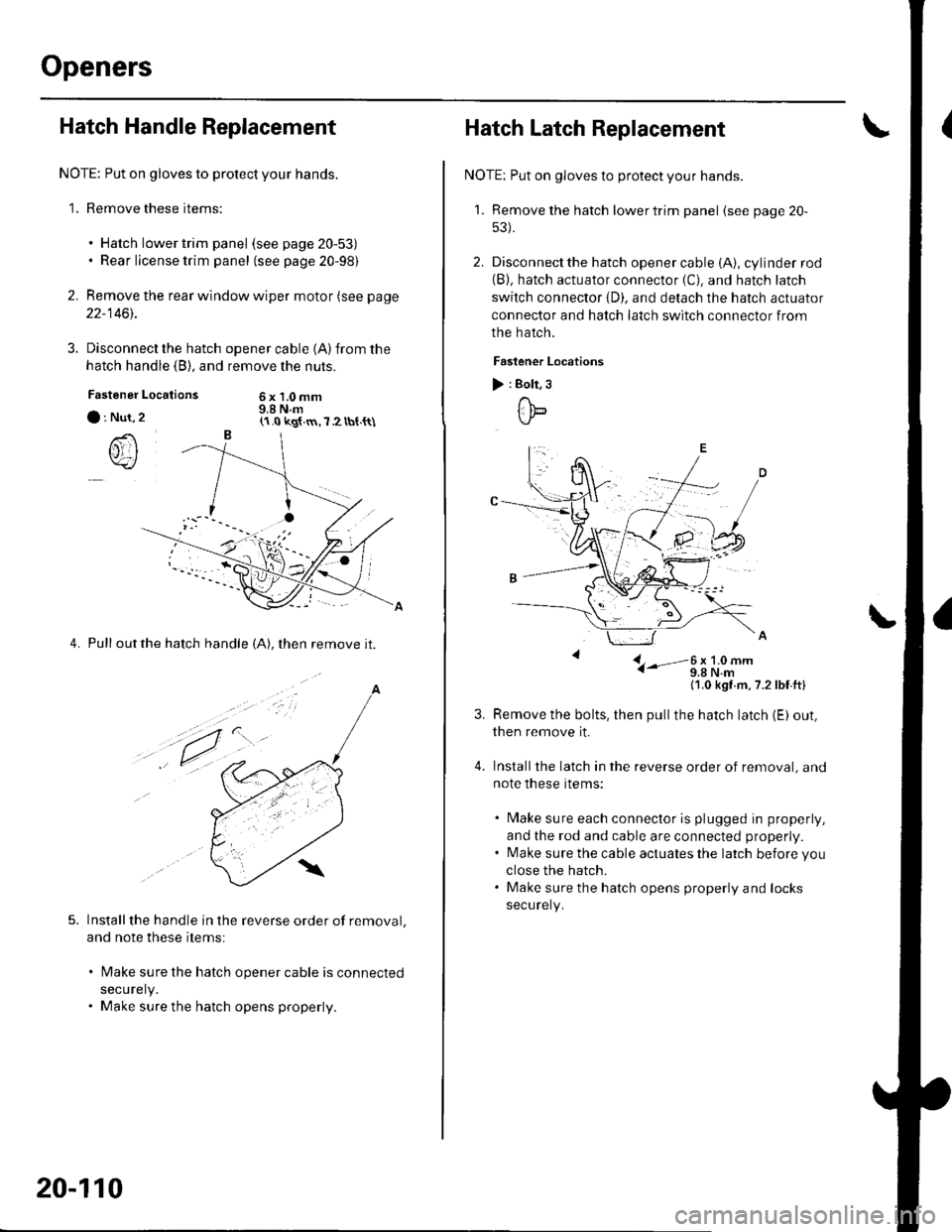
3. Disconnect the hatch
hatch handle (B), and
Locations
opener cable 1A)from the
remove the nuts.
6x1.0mm9.8 N.mFastener
a : Nut,
()rI
4. Pull outthe hatch handle (A), then remove it.
Installthe handle in the reverse order of removal.
and note these items:
lMake sure the hatch opener cable is connected
securely.
Make sure the hatch opens properly.
(1.0 kg{.m,7 2 tbt.{t\
a
,t.
20-110
Hatch Latch Replacement
NOTE: Put on gloves to protect your hands.
'1. Remove the hatch lowertrim panel (see page 20-
53).
2. Disconnect the hatch opener cable (A), cylinder rod(B). hatch actuator connector (C). and hatch latch
switch connector {D). and detach the hatch actuator
connector and hatch latch switch connector from
the hatch.
Faslener Locations
) : Bolt, 3
ttb
L- i-'-3;li9#-
11,0 kgt m,7.2lbf ftl
Remove the bolts, then pullthe hatch latch (E) out,
then remove it.
Installthe latch in the reverse order of removal, and
note these items:
. Make sure each connector is plugged in properly,
and the rod and cable are connected properly.. l\4ake sure the cable actuates the latch before you
close the hatch.. Make sure the hatch opens properly and locks
securely.
Page 765 of 1139
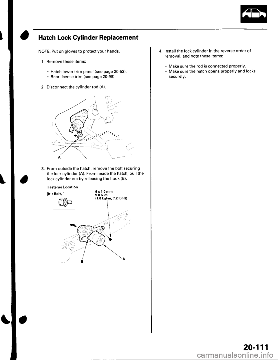
Hatch Lock Cylinder Replacement
NOTE; Put on gloves to protect your hands.
'1. Remove these items:
. Hatch lower trim panel (see page 20-53).. Rear license trim (see page 20-98).
2. Disconnect the cylinder rod (A)
-..
From outside the hatch, remove the bolt securing
the lock cylinder {A}. From inside the hatch, pull the
lock cylinder out by releasing the hook (B).
Fastener Location
> : Bolt, 1
rS'l-.u-ar
6x 1.0 mm9.8Nm(1.0 kgf m,7.2lbt.ftl
*/t
4. Install the lock cylinder in the reverse order of
removal, and note these items:
. Make sure the rod is connected properly.
. Make sure the hatch opens properly and locks
securely.
20-111
Page 816 of 1139
13. Installthe heater core and the evaporator core in
the reverse order of removal.
14. Installthe heater unit in the reverse order of
removal, and note these items:
. Do not interchange the inlet and outlet heater
hoses, and installthe hose clamps securely.. Refillthe cooling system with engine coolant (see
page 10-6).. Adjust the heater valve cable (see page 2'l-461.. Make sure that there is no coolant leakage.. Make sure that there is no air leakage.. Refer to evaporator core replacement {see step 6
on page 21-42).. Do the engine control module (ECl\4) idle learn
procedure (see page 11-139).. Enter the anti-theft code for the radio, then enter
the customer's radio station Dresets.
21-45
Page 835 of 1139
Body Electrical
General Troubleshooting Information (cont'd)
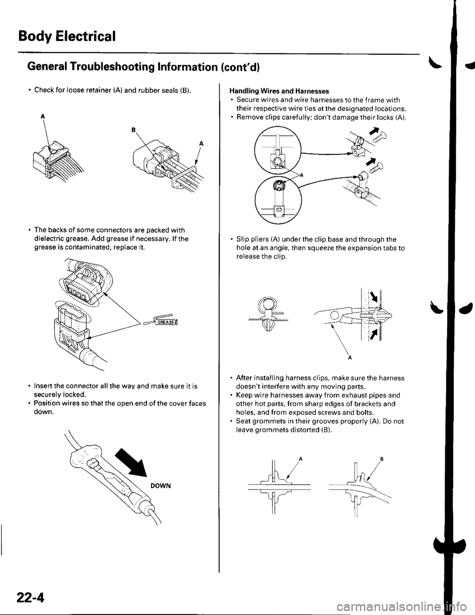
Check for loose retainer (A) and rubber seals (B).
The backs of some connectors are packed with
dielectric grease. Add grease if necessary. lf thegrease is contaminated, replace it.
lnsert the connector all the way and make sure it is
securelv locked.
Position wires so that the open end of the cover faces
oown.
22-4
Handling Wires and Harnesses. Secure wires and wire harnesses to lhe frame with
their respective wire ties at the designated locations.. Remove clips carefully; don't damage their locks (A).
Slip pliers (A) under the clip base and through the
hole at an angle, then squeeze the expansion tabs to
release the clip.
After installing harness clips, make sure the harness
doesn't interfere with any moving pans.
Keep wire harnesses away from exhaust pipes and
other hot parts, from sharp edges of brackets and
holes, and from exposed screws and bolts.
Seat grommets in their grooves properly {A). Do not
leave grommets distorted (B).
lt" /wl/
\--------\tfl r'---'..-
It
J
|,f . ./.ll t/
----E; F.�'l/
I
Page 837 of 1139
Body Electrical
General Troubleshooting Information (cont'dl
Five-step Troubleshooting
'1. Verify The Complaint
Turn on allthe components in the problem circuit
to verify the customer complaint. Note the
symptoms. Do not begin disassembly or testing
until you have narrowed down the problem area.
2. Analyze The Schematic
Look up the schematic for the problem circuit.
Determine how the circuit is supposed to work by
tracing the current paths from the power feed
through the circuit components to ground. lf
several circuits fail at the same time, the fuse or
ground is a Iikely cause.
Based on the symptoms and your understanding of
the circuit operation, identify one or more possible
causes of the problem.
3. lsolate The Problem By Testing The Circuit
Make circuit tests to check the diagnosis you made
in step 2. Keep in mind that a logical, simple
procedure is the key to efficient troubleshooting.
Test for the most likely cause of failure first, Try to
make tests at points that are easily accessible.
4. Fix The Problem
Once the specific problem is identified. make the
repair. Be sure to use proper tools and safe
proceoures.
5. Make Sure The Circuit Works
Turn on all components in the repaired circuit in all
modes to make sure you've fixed the entire
problem. lf the problem was a blown fuse, be sure
to test all of the circuits on the fuse. Make sure no
new problems turn up and the original problem
does not recur.
22-6
Wire Color Codes
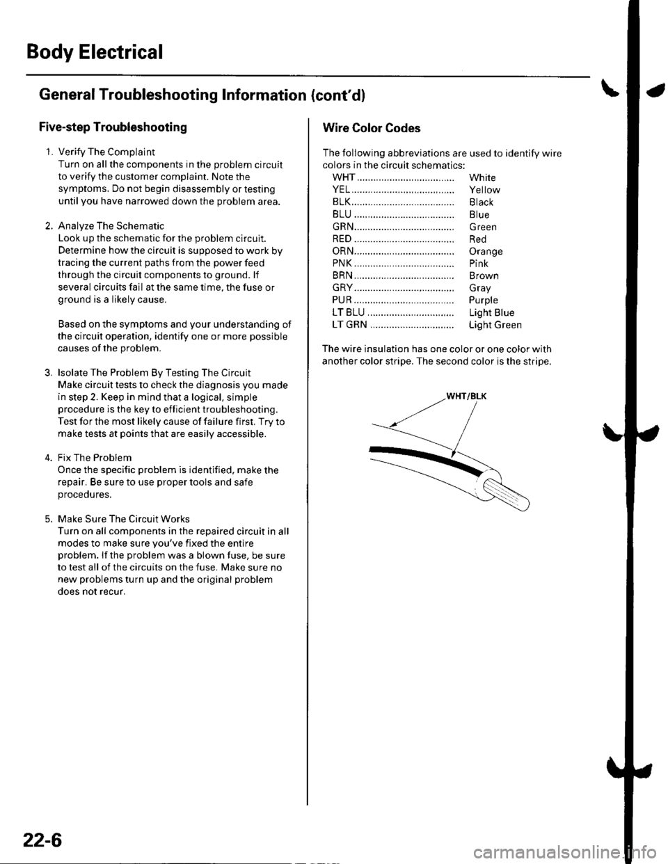
The following abbreviations are used to identify wire
colors in the circuit schematics:
wHT....................,.,.............
YEL......................,,.......,......
B1K......................................
BLU ....,................................
GRN.....................................
RED ....................................,
oRN.....................................
PNK..........................,..........
BRN.....................................
GRY....................................,
PUR.....................................
1T81U..........................,.....
1TGRN...........................,...
White
Yellow
Black
Blue
Green
Red
Orange
Pink
Brown
Gray
Purple
Light Blue
Light Green
The wire insulation has one color or one color with
another color stripe. The second color is the stripe.
Page 857 of 1139
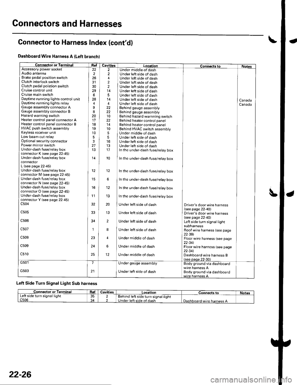
Connectors and Harnesses
Dashboard Wire Harness A {Left branchl
Connector or TerminalffiAccessory power socketAudio antennaBrake pedal position switchClutch interlock switchClutch pedal poistion switchCruise control unitCruise main switchDaytime r!nning lights control unitDaytime running lights relayGauge assembly connector AGauge assembly connector BHazard warning switchHeater control panel connector AHeater control panel connector BHVAC push switch assemblyKeyless receiver unitLow beam cut relayOptional security connectorPower mirror switchUnder-dash fuse/relay boxconnector K (see page 22-45)Under'dash fuse/relay box
L {see page 22-45}Underdash fuse/relay boxconnector M lsee page 22'45)Under-dash fuse/relay boxconnector N (see page 22-45)UndeFdash fuse/relay boxconnector O (see page 22-45)UndeFdash fuse/relay boxconnectorY (see page 22 45)c504
c505
c506
c507
c508
c509
c510
22226
3029628
I820111819105327
,I4
12
11
34
1
24
25
2 Under middle of dash2 Under left side of dash4 ] Under left side of dash2 ] Under left srde of dash2 | Under left side of dash14 I Under left side of dash5 Under left side of dash14 Under lett side of dash4 Under lett side of dash22 I Behind gauge assembly22 i Behind gauge assembly10 Behind hazard warnning switch22 Behind heater control panel'14 Behind heater control panel10 ] Behind HVAC switch assembly5 I Under middle of dash5 lUnderleftsideofdash16 Under lefr side of dash13 Under left side oI dash17 ln the under-dash fuse/relay box
CanadaCanada
l0In the under-dash fuse/relay box
In the undeFdash fuse/relay box
In the underdash fuse/relay box
In the under-dash fuse/relay box
In the under-dash fuse/relay box
Under left side of dash
Under left side ot dash
Under left side of dash
Under left side of dash
Under middle of dash
Under middle of dash
Under middle ol dash
Driver's door wire harness(see page 22'40)Driver's door wire harness(see page 22-40)Left side turo signal lightsuonarnessRoof wire harness (see page22 3AlFloor wire harness {see page22-341Floor wire harness (see page22 34JDashboard wire harness B(see oaoe 22-30)
12
12
G501
G503
1
21
Under gauge assembly
Under left side of dash
Body ground via dashboard
Body ground via dashboard
Left Side Turn Signal Light Sub harness
Connector to Harness Index (cont'd)
L
Connector or TerminalCavitiesLocationConnects toNolesLeft side turn signal lightc506353422Behind left side turn signal lightUnder left side of dashDashboard wire harness A
22-26
Page 878 of 1139
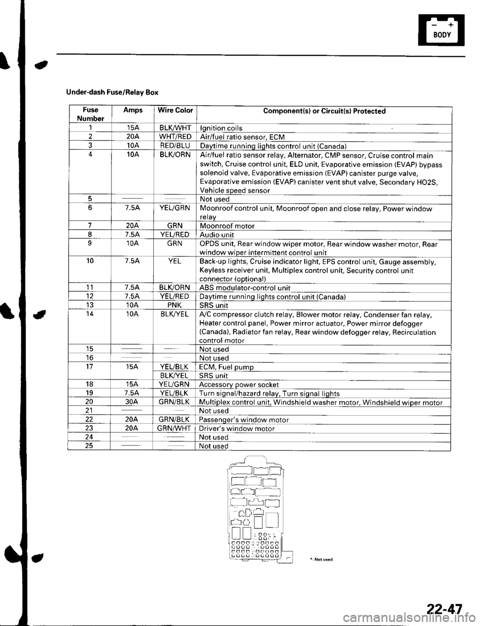
Under-dash Fuse/Relay Box
Fuse
Number
AmpsWire ColorComponent(s) or Circuit(s) Protected
115ABLKA/VHTlgnition coils
2204WHT/REDAirlfuel ratio sensor, ECM
310ARED/BLUDaytime running Iights control unit {Canada)10ABLI(ORNAir/fuel ratio sensor relay, Alternator, CMP sensor, Cruise control main
switch, Cruise control unit. ELD unit, Evaporative emission (EVAP) bypass
solenoid valve, Evaporative emission (EVAP)canister purge valve,
Evaporative emission (EVAP) canister vent shut valve, Secondary H02S,
Vehicle speed sensor
5Not used
67.5AYEUGRNMoonroof control unit, Moonroof open and close relay, Power window
relaV
7204GRNMoonroof motor
I7.5AYEUREDAudio unit
910AGRNOPDS unit, Rear window wiper motor, Rear window washer motor, Rear
window wiper intermittent control unit
107.54YELBack-up lights, Cruise indicator light, EPS control unit, Gauge assembly,
Keyless receiver unit, Multiplex control unit, Security control unit
connector (optional)
117.5ABLIVORNABS modulator-control unit
127.5AYEUREDDaytime runnino liohts control unit (Canada)
1310APNKSRS unit't410ABLK/YE LA,,/C compressor clutch relay, Blower motor relay, Condenser fan relay,
Heater control panel, Power mirror actuator, Power mirror defogger(Canada), Radiator fan relay, Rear window defogger relay, Recirculation
control motor1ENot used
loNot used
1715AYE L/B LKECM, Fuel pump
B LK/YE L>H> Unrr
1815AYEUGRNAccessory power socket
197.5AYEUBLKTurn siqnal/hazard relav, Turn siqnal liohts
2030AGRN/BLKMultiplex control unit, Windshield washer motor. Windshield wioer motor21Not used
22204GRN/BLKPassenqer's window motor
2320A.G R N,A/VHTDriver's window motor
24Not used
25Not used
__^:Hr tl_l
f at-t
at I
r^,rl fl
!!;r -
!339,i;s!!sf Fnf : |rnITf
22-47