fuse HONDA CIVIC 2002 7.G Workshop Manual
[x] Cancel search | Manufacturer: HONDA, Model Year: 2002, Model line: CIVIC, Model: HONDA CIVIC 2002 7.GPages: 1139, PDF Size: 28.19 MB
Page 947 of 1139
Power Mirrors
Function Test
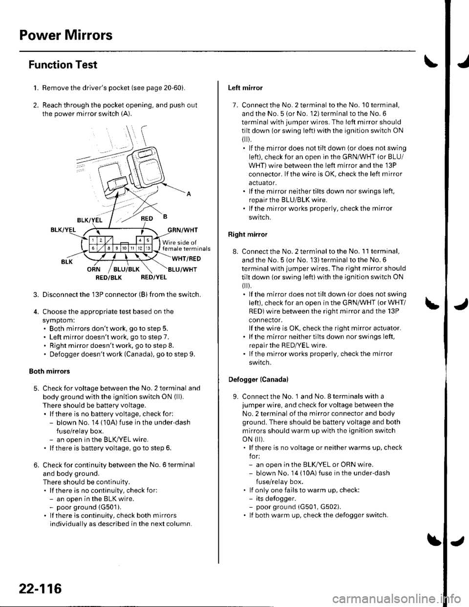
1. Remove the driver's pocket (see page 20-60).
2. Reach through the pocket opening, and push out
the power mirror switch (A).
,\
RED B
Wire side oftemale terminals
WHT/RED
RED/YEL
3. Disconnectthe'13P connector (B) from the switch.
4. Choose the appropriate test based on the
symptom:. Both mirrors don't work, go to step 5.. Left mirror doesn't work, go to step 7.. Right mirror doesn't work, go to step 8.. Defogger doesn't work (Canada), go to step 9.
Both mirrors
5. Check for voltage between the No. 2 terminal and
body ground with the ignitlon switch ON (ll).
There should be battery voltage.. lf there is no battery voltage, check for:- blown No. 14 (10A) fuse in the under'dash
fuse/relay box.- an open in the BLKryEL wire.. lf there is battery voltage, goto step 6.
6. Check for continuity between the No. 6 terminal
and body ground.
There should be continuity.. lf there is no continuity, check for:- an open in the BLK wire.- poor ground (G501).
. lf there is continuity, check both mirrors
individually as described in the next column.
RED/BLK
22-116
Left mirror
7. Connect the No. 2 terminal totheNo. l0terminal,
and the No. 5 (or No. 12) terminal to the No. 6
terminal with jumper wires. The left mirror should
tilt down (or swing left)with the ignition switch ON
fl r).. lf the mirrordoes nottiltdown (ordoes notswing
left), check for an open in the GRN/WHT (or BLU/
Wl-lT)wire between the left mirror and the 13P
conneclor, lf the wire is OK, check the left m irror
actualor.. lf the mirror neithertilts down nor swings left.
repair the BLU/BLK wire.. lf the mirrorworks properly, checkthe mirror
SWIICN,
Right mirror
8. Connect the No. 2 terminalto the No. 11 terminal,
and the No. 5 {or No. 13) terminal to the No. 6
terminal with jumper wires. The right mirror should
tilt down (or swing left)with the ignition switch ON
(
).. lf the mirror does not tilt down (or does not swing
left), check for an open in the GRN/WHT (or WHT/
RED)wire between the right mirror and the 13P
connector.
lf the wire is OK, check the right mirror actuator.. lf the mirrorneithertiltsdown norswings left,
repalr the RED|YEL wire.' lf the mirrorworks properly. checkthe mirror
swrrcn.
Defogger (Canada)
9. Connect the No. 1 and No. I terminals with a
jumper wire, and check for voltage between the
No. 2 terminal of the mirror connector and body
ground. There should be battery voltage and both
mirrors should warm up with the ignition switch
oN
t).. lf there is novoltage orneitherwarms up, check
for:- an open in the BLKI/EL or oRN wire.- blown No. 14 ('l0A)fuse in the under-dash
fuse/relay box.. lf only one fails to warm up, check:- its defogger.- poor ground (G501, G502). lf both warm up, checkthedefoggerswitch.
Page 951 of 1139

Horns
\Component Location Index
HORN RELAYTest, page 22-51
HORNSTest, page 22 122Beplacement, page 22 122
UNDER-HOOD FUSE/RELAY BOX
.- :.."'
HORN SWITCHfesl, page22-122
CABLE REELReplacement, page 23,1 19
22-120
*r
Page 953 of 1139
Horns
1.
3.
Horn Test/Replacement
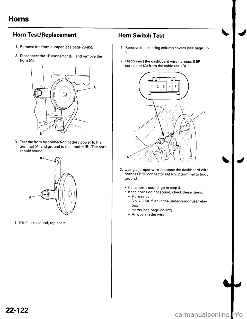
Remove the front bumper {see page 20-85).
Disconnect the 1P connector (B), and remove thehorn (A).
Test the horn by connecting battery power to the
terminal (A) and ground to the bracket (B). The horn
should sound.
4. lf it fails to sound, replace it.
22-122
1.
Horn Switch Test
Remove the steering column covers (see page '17-
9).
Disconnecl the dashboard wire harness B 5P
connector (A) from the cable reel (B).
Using a jumper wire . connect the dashboard wire
harness B 5P connector (A) No. 2 terminal to bodyground .
. lf the horns sound, goto step 4.. lf the horns do notsound, checkthese items:- Horn relay- No.7 (15A)fuse in the under-hood fuse/relay
box- Horns (see page 22-122).- An open in the wire
| ../......:....,
Page 955 of 1139
Power Windows
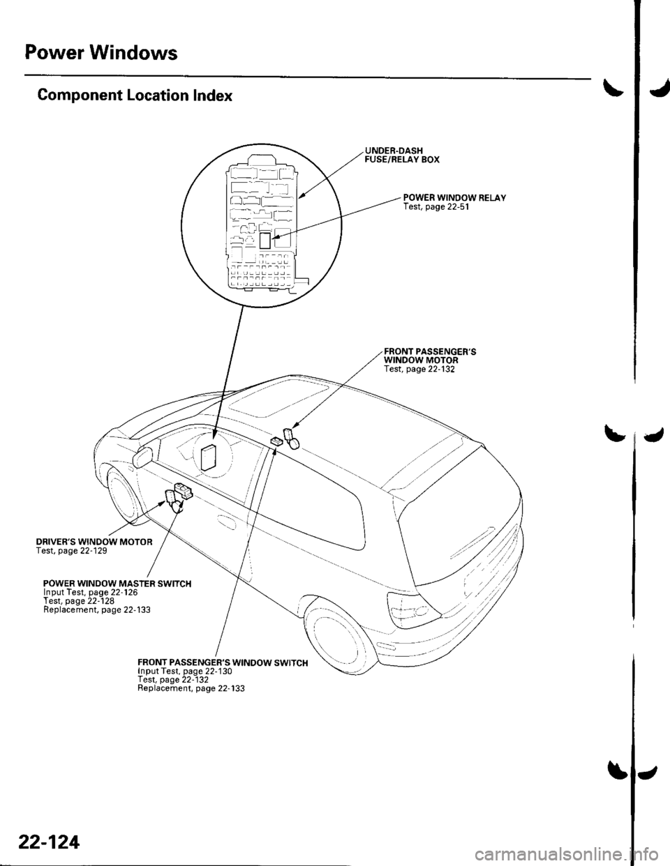
IJComponent Location Index
DRIVER'S WINDOW MOTORTest, page 22-129
UNDER.DASHFUSE/RELAY BOX
POWER WINDOW RELAYIest, page 22-51
FRONT PASSENGER'SWINDOW MOTORTest, page 22-132
tJ
POWER WINDOW MASIER SWITCHInput Test. Daqe 22.126Test, page 22--128Replacement, page 22-133
FRONT PASSENGER'S WINDOW SWITCHInDut Tesl, paqe 22-130f est, page 22-132Beplacement, page 22-133
al.l ' -f..--.--
L-.::
22-124
\J
Page 958 of 1139
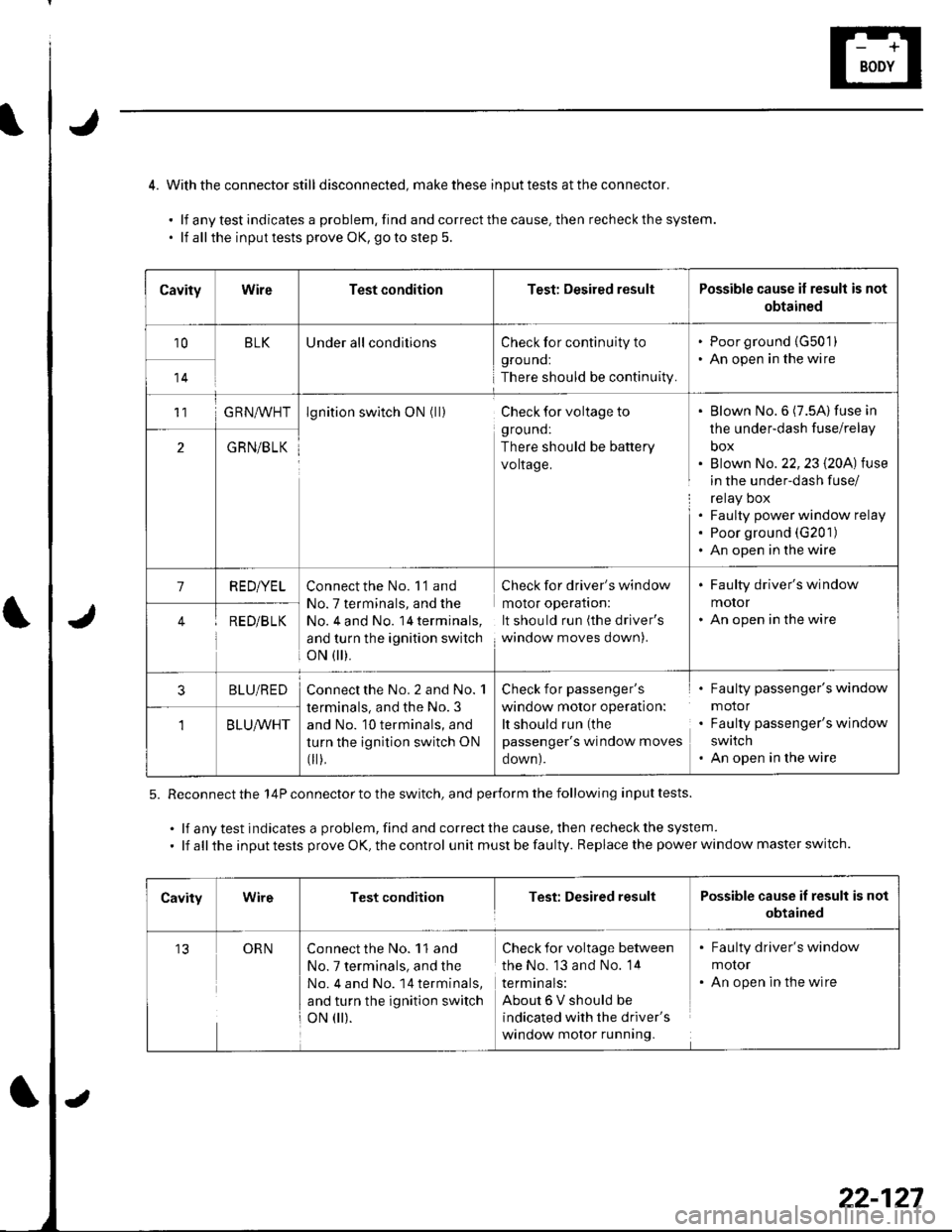
4. Withthe connector still disconnected, makethese inputtests attheconnector.
.lfanytestindicatesaproblem,findandcorrectthecause.thenrecheckthesystem.
. lf allthe inputtests prove OK, goto step 5.
5. Reconnect the 14P connector to the switch, and perform the following input tests.
.lfanytestindicatesaproblem,findandcorrectthecause,thenrecheckthesystem.
. lf all the input tests prove OK, the control unit must be faulty. Replace the power window master switch.
CavityWireTest conditionTest: Desired resultPossible cause if result is not
obtained
10BLKUnder all conditionsCheck for continuity to
grouno:
There should be continuity.
. Poor ground {G50'1). An open in the wire
14
11G RN^,^/HTlgnition switch ON (ll)Check for voltage to
ground:
There should be battery
voltage.
Blown No.6 (7.5A) fuse in
the under-dash fuse/relay
box
Blown No. 22,23 l2OA) tuse
in the under-dash fuse/
relay Dox
Faulty power window relay
Poor ground (G201)
An open in the wire
2GRN/BLK
1RED/YELConnect the No. 'l'1 and
No. 7 terminals, and the
No, 4 and No. 14 terminals,
and turn the ignition switch
oN flr).
Check for driver's window
molor operaflon:
It should run (the driver's
window moves down).
. Faulty driver's window
motor. An open in the wireRED/B LK
3BLU/REDConnect the No. 2 and No. 1
terminals, and the No. 3
and No. 10 terminals, and
turn the ignition switch ON
fi r),
Check for passenger's
window motor operation:
It should run (the
passenger's window moves
oown).
Faulty passenger's window
motor
Faulty passenger's window
swatch
An open in the wire
BLU/WHT
CavityWireTest conditionTest: Desired resultPossible cause if result is not
obtained
13ORNConnect the No. 11 and
No. 7 terminals, and the
No. 4 and No. 14 terminals,
and turn the ignition switch
oN 0r).
Check for voltage between
the No. 13 and No. 14
termtnals:
About6Vshouldbe
indicated with the driver's
window motor running.
. Faulty driver's window
molor. An open in the wire
22-127
Page 961 of 1139
Power Windows
1.
2.
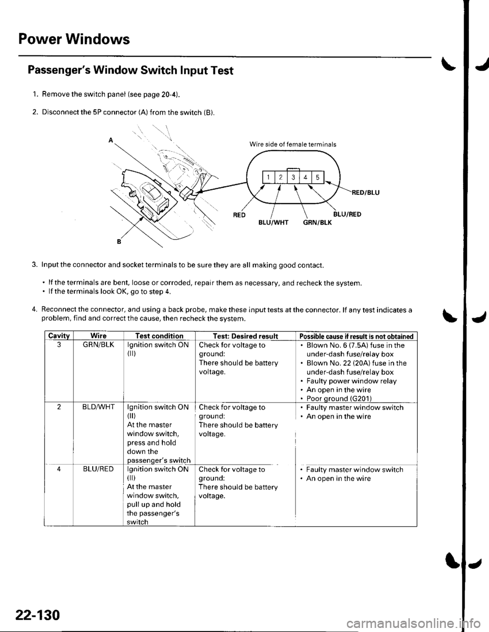
Passenger's Window Switch Input Test
Remove the switch panel (see page 20-4).
Disconnect the 5P connector (A) from the switch (B).
o
'' "'"1.
4.
Wire side of female terminals
BLU/WHTGRN/BLK
Input the connector and socket terminals to be sure they are all making good contact.
. lf theterminals are bent, loose or corroded, repairthem as necessary, and recheckthe system.. lf the terminals look OK, go to step 4.
Reconnect the connector, and using a back probe, make these input tests at the connector. lf any test indicates aproblem, find and correct the cause, then recheck the svstem,
CavitvWireTest conditionTest: Desired resultPossible cause if result is not obtained
3GRN/BLKlgnition switch ON
{ ll)
Check for voltage to
grouno:
There should be battery
voltage.
Blown No.6 (7,5A)fuse in the
under-dash fuse/relay box
Blown No.22 {20A)fuse in the
under-dash fuse/relay box
Faulty power window relay
An open in the wire
Poor qround (G201)
2BLD,A/VHTlgnition switch ON( )
At the master
window switch,
press and hold
down the
passenger's switch
Check for voltage to
ground:
There should be battery
voltage.
Faulty master window switch
An open in the wire
BLU/REDlgnition switch ON(||)
At the master
window switch,
pull up and hold
the passenger's
switch
Check for voltage to
grouno:
There should be battery
voltage.
Faulty master window switch
An open in the wire
22-130
Page 965 of 1139
Wipers/Washers
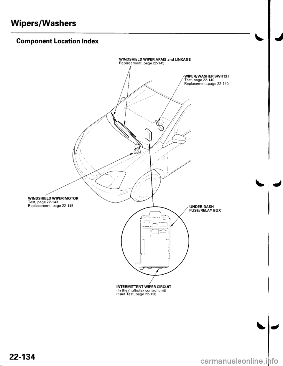
Component Location Index
WINDSHIELD WIPER MOTORTest, page 22-'143Replacement, page 22-145
WINDSHIELD WIPER ARMS and LINKAGEReplacement, page 22-'145
WIPER/WASHER SWITCHTest, page 22-140Replacement,page 22 140
UNDER.DASHFUSE/RELAY BOX
INTERMITTENT WIPER CIRCUITlln the multiplex control unit)Input Test, page 22-138
22-134
Page 968 of 1139
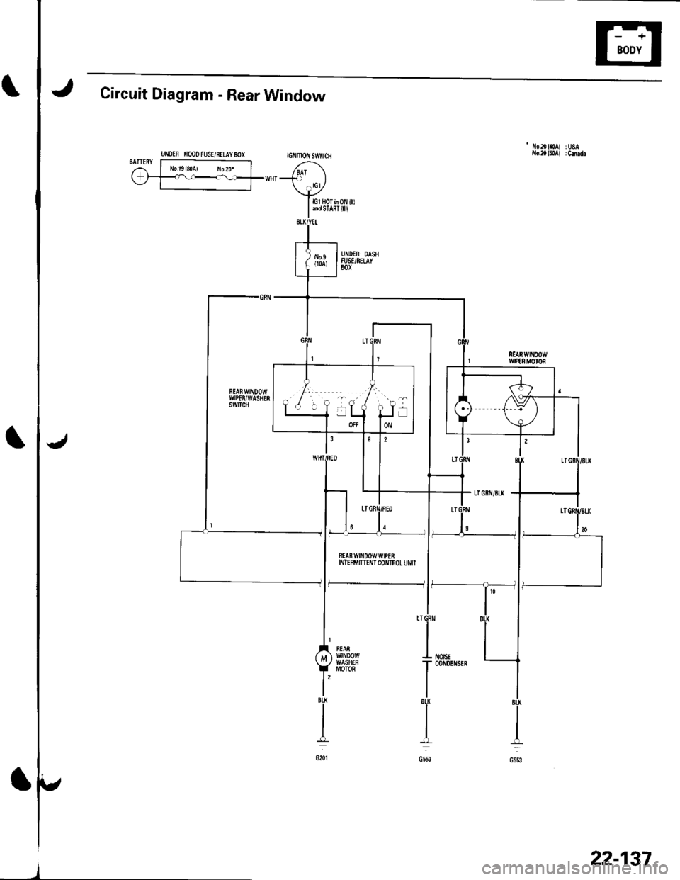
Circuit Diagram - Rear Window
UI\IOIF H@O FUSE/RELAY MX GNMOIIISW|ICH
- No2olaoAl :USA
BATTERY r----------------;i l No'g,soA, ro2o. | /,^1\(-;1_=l----_--_fww{"-' l
\+ylErHorb0Ni||l
I andsra8r 0
ffAn w$tDow wtPEEINTE$'ITTEI'IT C{)NNOL UI'/IT
f--------------- li
22-137
Page 970 of 1139
\
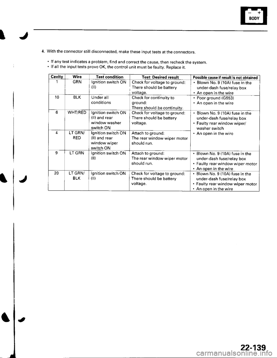
4. With the connector still disconnected, makethese input tests at the con necrors.
.lfanytestindicatesaproblem,findandcorrectthecause,thenrecheckthesystem.
' lf all the input tests prove OK, the control unit must be faultv. Replace it.
CavitvWireTesl conditionTest: Desired resultPossible cause if result is not obtainedGRNlgnition switch ON
flr)
Check for voltage to ground:
There should be battery
voltaqe.
. Blown No.9 (10A)fuse in the
under-dash fuse/relay box. An open in the wire10BLKUnder all
conditions
Check for continuity to
grouno:
There should be continuitv.
Poor ground (G553)
An open in the wire
6WHT/REDlgnition switch ON(ll) and rear
window washer
switch ON
Check for voltage to ground:
There should be battery
vortage.
Blown No.9 (10A) fuse in the
under-dash fuse/relay box
Faulty rear wlndow wiper/
washer switch
An open in the wire4LT GRN/
RED
lgnition switch ON(ll) and rear
window wiper
switch ON
Attach to groundl
The rear window wiper motor
should run.
LT GRNlgnition switch ON
flr)
Attach to ground:
The rear window wiper motor
should run.
Blown No. 9 (10A)fuse in the
under-dash fuse/relay box
Faulty rear window wiper motor
An open in the wire20LT GRN/
BLK
lgnition switch ON(ll)Check for voltage to ground:
There should be battery
voltage.
Blown No.9 (10A) fuse in the
under-dash fuse/relay box
Faulty rear window wiper motor
An oDen in the wire
22-139
Page 972 of 1139
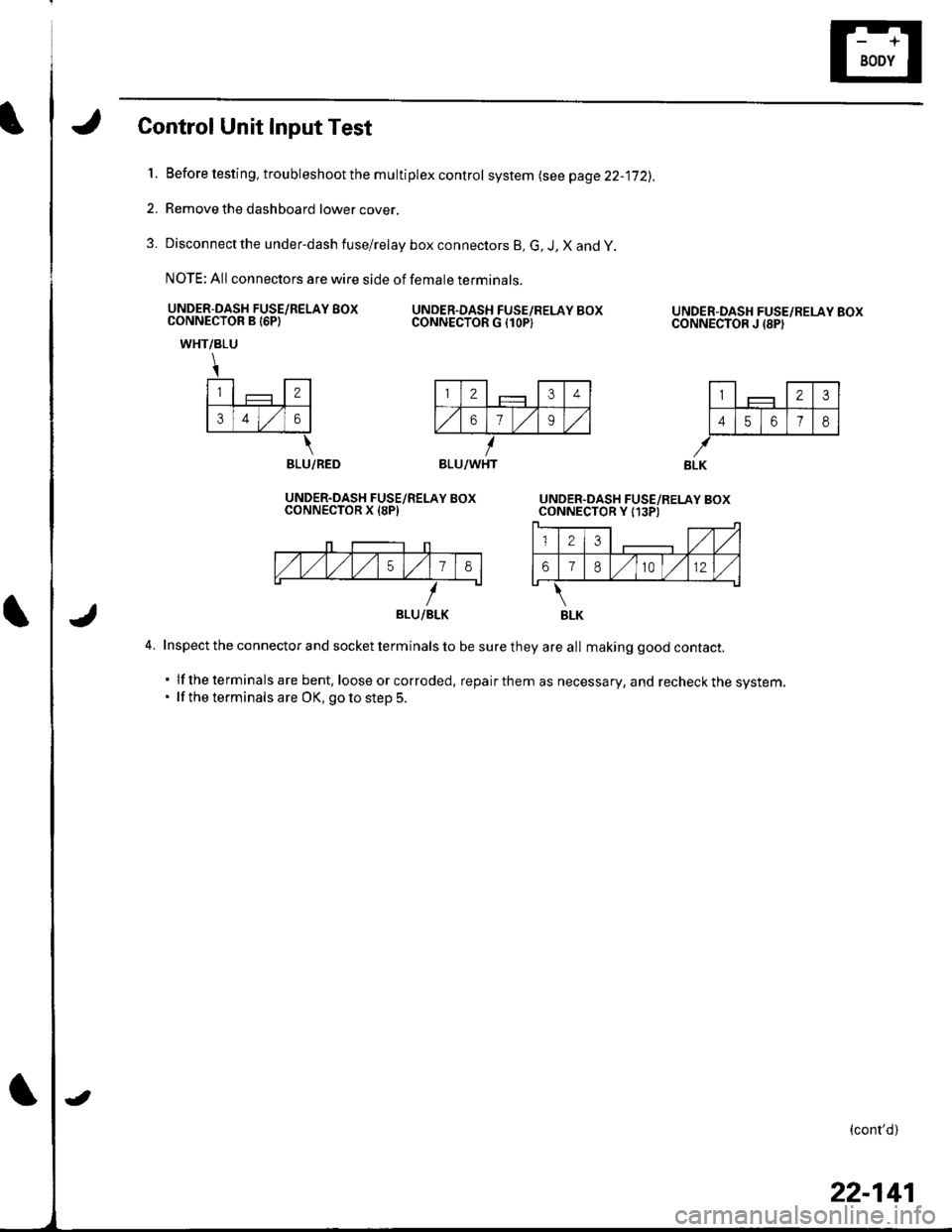
Control Unit Input Test
l.Before testing, troubleshoot the multiplex control system lsee page 22-jj2).
Remove the dashboard lower cover,
Disconnect the under-dash fuse/relay box connectors B, G, J, X and y
NOTE: All connectors are wire side of female terminals.
UNDER-DASH FUSE/RELAY BOXCONNECTOR B I6PIUNDER.DASH FUSE/RELAY BOXCONNECTOR G {1OP)
2.
3.
UNDER-DASH FUSE/RELAY BOXCONNECTOR J {8PI
l-,1 - llTtlF_j-JF-#
141516 7l8l
WHT/BLU
\
l-,1 - l-rl€ll
lslrlzlol
\BLU/RED
UNDER.DASH FUSE/RELAY BOXCONNECTOR X I8PI
4. Inspect the connector and socket terminals to be sure they are all making good contact.
. lf the terminals are bent, loose or corroded, repairthem as necessary, and recheckthe system.. lf the terminals are OK, goto step 5.
(cont'd)
BLU/WHT
BLU/BLK
22-141