fuse HONDA CIVIC 2002 7.G Manual Online
[x] Cancel search | Manufacturer: HONDA, Model Year: 2002, Model line: CIVIC, Model: HONDA CIVIC 2002 7.GPages: 1139, PDF Size: 28.19 MB
Page 805 of 1139
Heating and Air Conditioning
Air Mix Control Motor Test
1. Disconnect the 5P connector from the air mix
control motor.
2. Connect battery powertothe No. l terminal ofthe
air mix control motor, and ground the No. 2
terminal; the air mix control motor should run, and
stop at Max Cool. lf it doesn't, reverse the
connections;the air mix control motor should run,
and stop at Max Hot. lf the air mix control motor
does not run, remove it. then check the air mix
control linkage and door for smooth movement.
. lf the linkage and door move smoothly, replace
the air mix control motor.. lf the linkage ordoorstickor bind, repairthem as
needed.. lf the air mix control motor runs smoothly, go to
step 3.
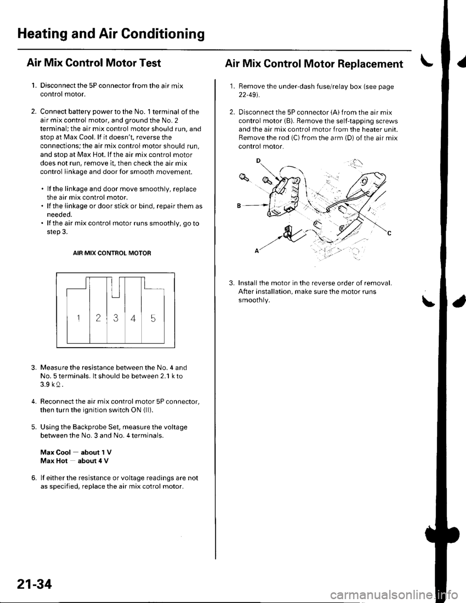
AIR MIX CONTROL MOTOR
3.
4.
Measure the resistance between the No. 4 and
No. 5 terminals. lt should be between 2.1 k to
3.9 kQ.
Reconnect the air mix control motor 5P connector,
then turn the ignition switch ON {ll).
Using the Backprobe Set, measure the voltage
between the No. 3 and No. 4 terminals.
Max Cool about 1V
Max Hot about 4 V
lf either the resistance or voltage readings are not
as specified, replace the air mix cotrol motor.
21-34
Air Mix Control Motor Replacement
1.Remove the under-dash fuse/relay box (see page
22-491.
Disconnect the 5P connector {A) from the air mix
control motor (B). Remove the self-tapping screws
and the air mix control motor from the heater unit.
Remove the rod (C) from the arm (D) of the air mix
controi motor.
Install the motor in the reverse order of removal.
After installation, make sure the motor runs
smoothly.
3.
\'
,.,:l'
Page 808 of 1139
Evaporator Temperature Sensor
Replacement
1.Remove the driver's dashboard lower cover (see
page 20-59) and the under cover (see page 20-60).
Remove the under-dash fuse/relay box (see page
22-491.
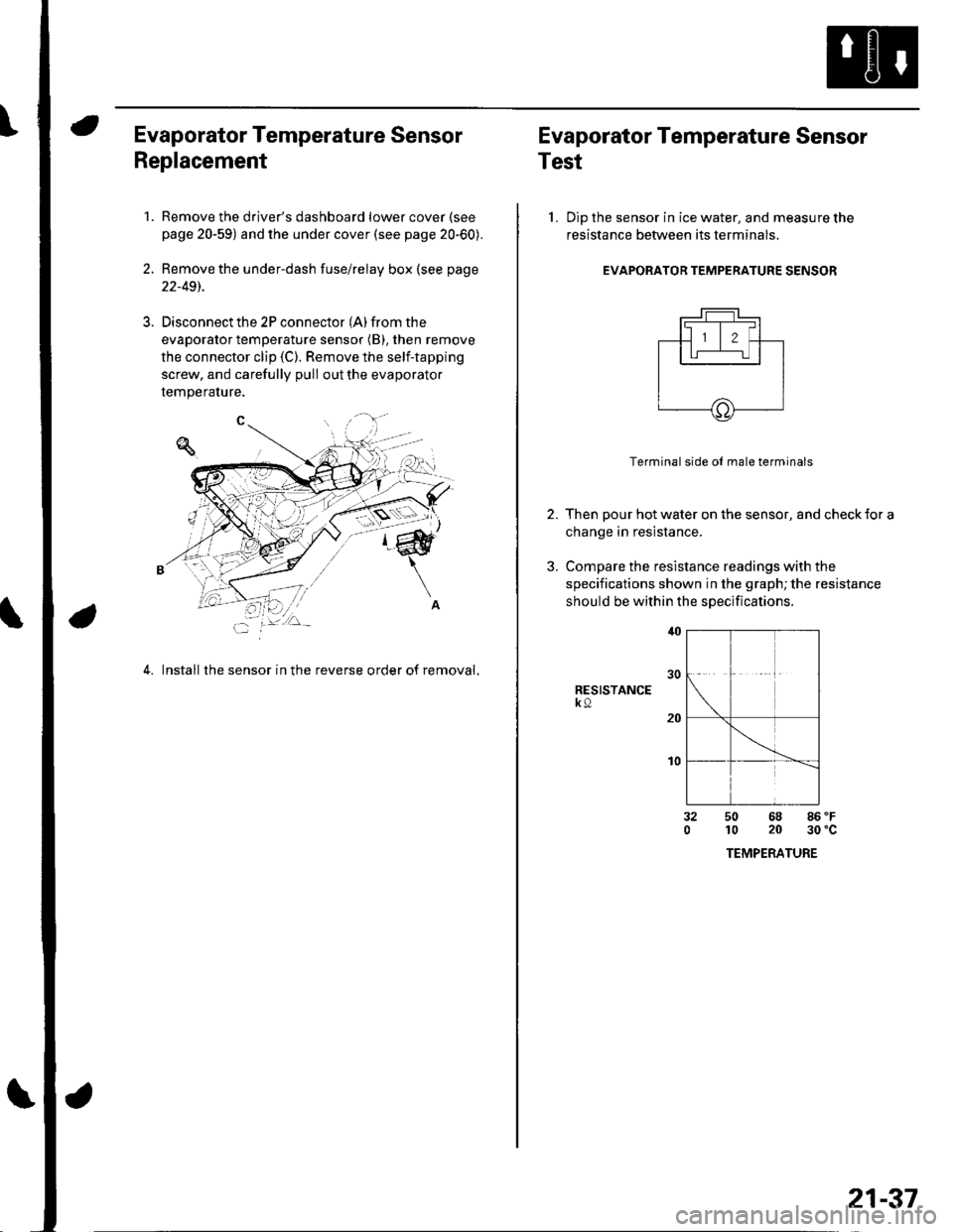
Disconnect the 2P connector (A) from the
evaporator temperature sensor (B), then remove
the connector clip (C). Remove the self-tapping
screw, and carefully pull out the evaporator
temperature.
4. Install the sensor in the reverse order of removal,
Evaporator Temperature Sensor
Test
l. Dip the sensor in ice water, and measure the
resistance between its terminals
EVAPORATOR TEMPERATURE SENSOR
2.
3.
Terminal side ol male terminals
Then pour hot water on the sensor, and check {or a
change in resistance.
Compare the resistance readings with the
specifications shown in the graph; the resistance
should be within the specifications
RESISTANCEk9
t0
32050 68 86 'F
10 20 30'c
TEMPERATURE
21-37
Page 831 of 1139
\Body Electrical
Body ElectricalSpecialToolsGeneral Troubleshooting tntorrnaiion.'......
Relay and Control Unit Locations .....
Connectors and Harnesses
Fuse/Relay Boxes ...............................
Power Distribution .............................
Ground Distribution ...........................
Under-dash Fuse/Relay Box ..............
Battery ..............
Relays ................
*lgnition Switch ..............
*Gauges
Component Location Index .......................Self-diagnostic Procedure ..........................Circuit DiagramGauge Bulb Replacement ..........................Gauge Assembly ReplacementCoolant Temperature
Gauge Troubleshooting .... ....................Vehicle Speed Signal CircuitTroubleshootingVSS Replacement
Exterior LightsComponent Location Index .......................Circuit DiagramDaytime Running Lights ControiUnit Input Test (Canada) ........................Headlight Ad,ustment .................. .. .....Headlighr Replacement ..............................Combination Light SwitchTest/ReplacementBulb ReplacementTaillight Replacement ..........................High Mount Brake Light Replacement ......License Plate Light Replacement ..............Side Marker Light Replacement ................Brake Pedal Position Switch Test ..............Side Turn Signal Light Replacement ........
Turn Signal/HazardFlasher SystemComponent Location Index .......................Circuit DiagramTurn Signal/Hazard Relay lnputTest ........Hazard Warning Switch Test
22,3
22-7
22-13
22-44
22-46
22-4A
22-49
22-50
22-51
22-53
22-5422-5622-5422 6322-64
22-64
22-6522 61
22-6822--71
22-7 622-7422-79
22-AO22-4122-8222-4222-4322-4322-4422-84
22-8�522 A622-8722-88
22-10422-105
22-10622-107
Entry Lights control systemComponent Location Index ....................... 22-89Circuit Diagram ......... 22 90lgnition Key Switch Test .....................,...... 22-9'llgnition Key Light Test ............................... 22-91Control Unit Input Test ..........,.................... 22 92
Interior LightsComponent Location Index ....................... 22-94Circuit Diagram ......... 22-95Ceiling LighVSpotlightsTesVReplacement ................................... 22-96Rear Ceiling Light TesVReplacem ent ........ 22-96Cargo Area Light Test/Replacem ent ......... 22-97Hatch Latch Switch Test ..,..,....................... 22-97
*Audio SystemComponent Location Index ....................... 22-98Circuit Diagram ......... 22,99Audio Unit Removal/lnstallation ............... 22-1OOAudio Unit Connector Replacement ......... 22-101Speaker Replacement ................................ 22-102Roof Antenna Rep1acement ....................-.. 22-103
Rear Window DefoggerComponent Location Index ...........Circuit Diasram .. ....... .. ..... ....... ...:::::.::.::.Function TestDefogger Wire Repair .................................Noise Condenser CapacityTest ................
MoonroofComponent Location Index ....................... 22-1OBCircuit Diagram ......... 22-109Moonroof Control Unit Input Test ............. 22-'l10Switch TesVReplacement ........,.....,........... 22-1 12Motor Test ................. 22-112Limit Swilch Test ...... 22-'l'13Auto-stop Switch Test ................................ 22-1 13
Power MirrorsComponent Location Index ....................... 22-114Circuit Diagram ......... 22-115Function Test ............. 22-116Power Mirror Switch Test .......................... 22-ll7Power Mirror Actuator Test ....................... 22-117Power Mirror Actuator Replacement ........ 22-11A
* HornsComponent Location Index ....................... 22-120Circuit Diagram ......... 22-121Horn TesVReplacement ...........................-. 22-122Horn Switch Test .,.... 22-122
\
Page 834 of 1139
General Troubleshooting Information
Tips and Precautions
Bef ore Troubleshooting
1. Check applicable fuses in the appropriate fuse/relay
oox.
2. Check the battery for damage. state of charge, and
clean and tight connections.
. Do not quick-charge a battery unless the battery
ground cable has been disconnected, otherwise
you will damage the alternator diodes.. Do not attempt to crank the engine with the
battery ground cable loosely connected or you
will severely damage the wiring.
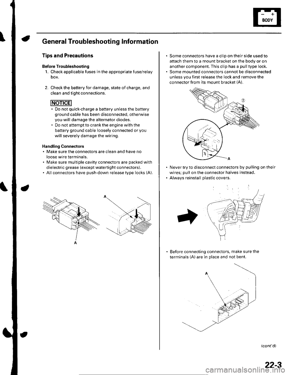
Handling Connectors. Make sure the connectors are clean and have no
loose wire terminals.. Make sure multiple cavity connectors are packed with
dielectric grease (except waterti ght connectors).. All connectors have push-down release type locks (A).
Some connectors have a clip on their side used to
attach them to a mount bracket on the body or on
another component. This clip has a pull type lock.
Some mounted connectors cannot be disconnected
unless you first release the lock and remove the
connector from its mount bracket (A).
Never try to disconnect connectors by pulling on their
wires; pull on the connector halves instead.
Alwavs reinstall Dlastic covers,
Before connecting connectors, make sure the
terminals (A) are in place and not bent.
(cont'd)
22-3
Page 837 of 1139
Body Electrical
General Troubleshooting Information (cont'dl
Five-step Troubleshooting
'1. Verify The Complaint
Turn on allthe components in the problem circuit
to verify the customer complaint. Note the
symptoms. Do not begin disassembly or testing
until you have narrowed down the problem area.
2. Analyze The Schematic
Look up the schematic for the problem circuit.
Determine how the circuit is supposed to work by
tracing the current paths from the power feed
through the circuit components to ground. lf
several circuits fail at the same time, the fuse or
ground is a Iikely cause.
Based on the symptoms and your understanding of
the circuit operation, identify one or more possible
causes of the problem.
3. lsolate The Problem By Testing The Circuit
Make circuit tests to check the diagnosis you made
in step 2. Keep in mind that a logical, simple
procedure is the key to efficient troubleshooting.
Test for the most likely cause of failure first, Try to
make tests at points that are easily accessible.
4. Fix The Problem
Once the specific problem is identified. make the
repair. Be sure to use proper tools and safe
proceoures.
5. Make Sure The Circuit Works
Turn on all components in the repaired circuit in all
modes to make sure you've fixed the entire
problem. lf the problem was a blown fuse, be sure
to test all of the circuits on the fuse. Make sure no
new problems turn up and the original problem
does not recur.
22-6
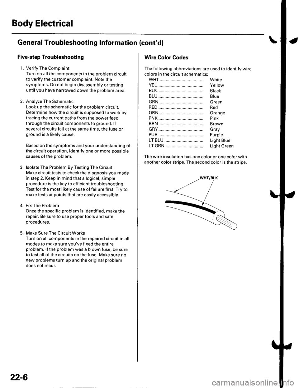
Wire Color Codes
The following abbreviations are used to identify wire
colors in the circuit schematics:
wHT....................,.,.............
YEL......................,,.......,......
B1K......................................
BLU ....,................................
GRN.....................................
RED ....................................,
oRN.....................................
PNK..........................,..........
BRN.....................................
GRY....................................,
PUR.....................................
1T81U..........................,.....
1TGRN...........................,...
White
Yellow
Black
Blue
Green
Red
Orange
Pink
Brown
Gray
Purple
Light Blue
Light Green
The wire insulation has one color or one color with
another color stripe. The second color is the stripe.
Page 838 of 1139
Relay and Control Unit Locations
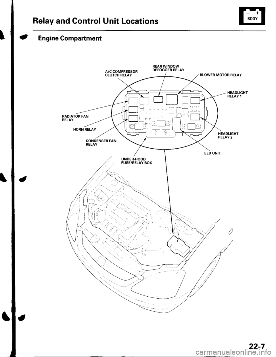
Engine Compartment
RADIATOR FANRELAY
BLOWER MOTOR RELAY
HORN RELAY
CONDENSER FANRELAY
UNDER-HOODFUSE/RELAY BOX
\...
,-:1-'...
ELD UNIT
22-7
Page 839 of 1139
Relay and Gontrol Unit Locations
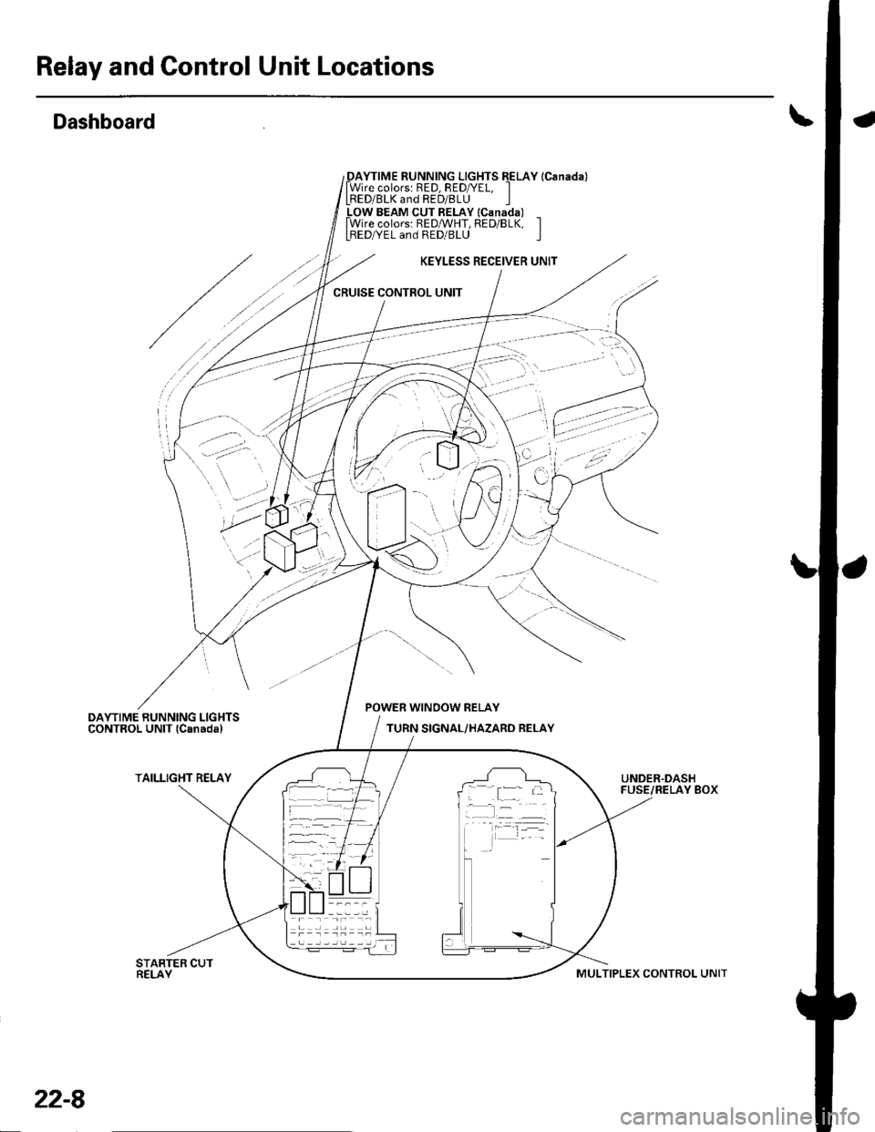
Dashboard
_DAYTIME RUNNING LIGHTS EELAY lCanada)lWire colorsr RED, RED/YEL, ILRED/BLK and RED/8LU I_LOW BEAM CUT RELAY lcanada) _lWire colors: REDMHT, RED/BLK, ILBEDA/EL and RED/BLU I
KEYLESS RECEIVER UNIT
CRUISE CONTROL UNIT
'
'-.:- ':
..? ;,
POWER WINOOW RELAY
TURN SIGNAL/HAZARD RELAY
TAILLIGHT RELAYUNDER.DASHFUSE/RELAY BOX; .[:_- -
-l:r --
22-8
MULTIPLEX CONTROL UNIT
Page 846 of 1139
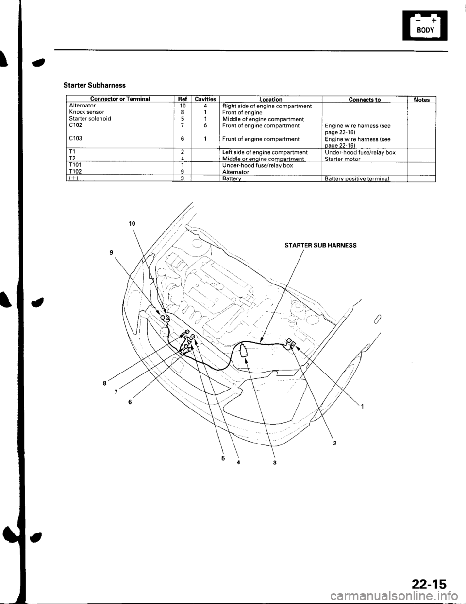
Connector or TerminalRetCavitiesLocationConnoc,ts toNotesAlternatorKnock sensorStarter solenoidc102
c103
10857
6
4116
1
Right side of eng;ne compartmentFront of engineMiddle of engine compartmentFront of engine compartment
Front of engane compartment
Engine wire harness (seepage 22 16)Engine wire harness (seeoaae 22-16)T1r224L€tt side of engine compartmentMiddle or enoine comDanmentUnder hood fuse/relay boxStaner motorT101r1021IUnder-hood fuse/relay boxAlternatorBattervBatterv positive terminal
Starter Subharness
STARTER SUB HARNESS
22-15
Page 851 of 1139
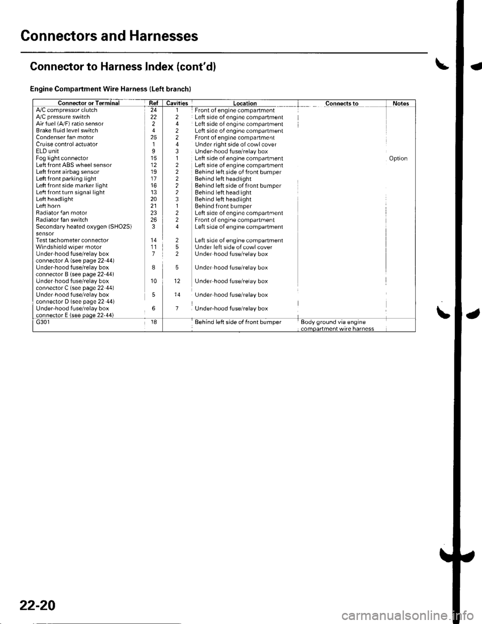
Connectors and Harnesses
Engine Compartment Wire Harness (Left branch)
AirJuel (A,,/F) ratio sensorBrake fluid level switchCondenser fan motorCruise control actuatorELD unitFog light connectorLeft front ABS wheel sensorLeft front airbag sensorLeft front parking lightLeft front side marker lightLeft lrontturn signal lightLeft headlightLeft hornRadiator fan motorRadiator fan switchSecondary heated oxygen (SHO2S)
Test tachometer connectorWindshield wiper motorUnder'hood fuse/relay boxconnector A {see page 22-44)Under-hood f use/relay boxconnector B (see page 22-44)Under hood fuse/relay boxconnector C (see page 22-44)Under hood fuse/relay boxconnector D (see page 22 44)Under-hood fuse/relay box
Front of engine companmentLeft side of engine compartmentLeft side of engine compartmentLeft side o{ engine compartmentFront of engine compartmentUnder right side of cowl coverUnder'hood f use/relay boxLeft side of engine compartmentLeft side of engine companmentBehind left side of front bumperBehind left headlightBehind left side of front bumperEehind left headlightBehind left headlightBehind front bumperLeft side of engine compartmentFront of engine compartmentLeft side of engine compartment
Left side of engine companmentL.Jnder left side of cowl coverL.Jnder hood fuse/relay box
L.Jnder hood fuse/relay box
L.Jnder'hood f use/relay box
underhood fuse/relay box
Under-hood fuse/relay box
24222
2519
12
17
13202123
3
117
I
10
5
6
l2
2243,l
222223l224
252
5
12
Connector to Harness Index (cont'dl
\
22-20
Page 853 of 1139
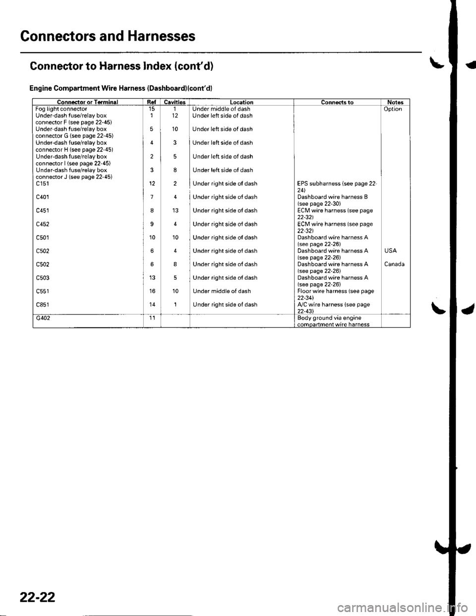
Connectors and Harnesses
Connector to Harness Index (cont'd)
Engine Compartment Wire Harness (Dashboard)lcont'dl
Connector or TerminalCavitiesLocationConnectstoNotesFog light connectorUnder'dash fuse/relay boxconnector F (see page 22-45)Underdash fuse/relay boxconnector G (see page 22-45)Underdash fuse/relay boxconnector H (see page 22'45)Under-dash fuse/relay boxconnector | (see page 22'45)Under-dash fuse/relay boxconnector J (see page 22-45)c 151
c401
c451
c452
c501
c502
c502
c503
c851'14
2
3
1
I
9
6
6
5
5
12
10
112
10
3
5
8
2
'10
4
8
5
10
1
Under maddle of dashUnder left side of dash
Under left side of dash
Under left side of dash
Under left side of dash
Under left side ol dash
Under right side of dash
Under right side ot dash
Under right side ot dash
Under right side oJ dash
Under right side oI dash
Under right side ol dash
Under right side oJ dash
Under right side oJ dash
Under middle of dash
Under right side of dash
EPS subharness {see page 22-24)Dashboard wire harness B(see page 22-30)ECM wire harness (see page22-321ECM wire harness (seo page22 32)Dashboard wire harness A(see page 22-26)Dashboard wire harness Alsee page 22-261Dashboard wire harness A(see page 22-26)Dashboard wire harness A(see page 22-26)Floorwire harness (see page22-34l',VC wire harness lsee page22-43\
Oplion
Canada
USA
G4021'�IEody ground via engine..mdarlma.t w,rc harncss
22-22