sensor HONDA CIVIC 2002 7.G Workshop Manual
[x] Cancel search | Manufacturer: HONDA, Model Year: 2002, Model line: CIVIC, Model: HONDA CIVIC 2002 7.GPages: 1139, PDF Size: 28.19 MB
Page 777 of 1139
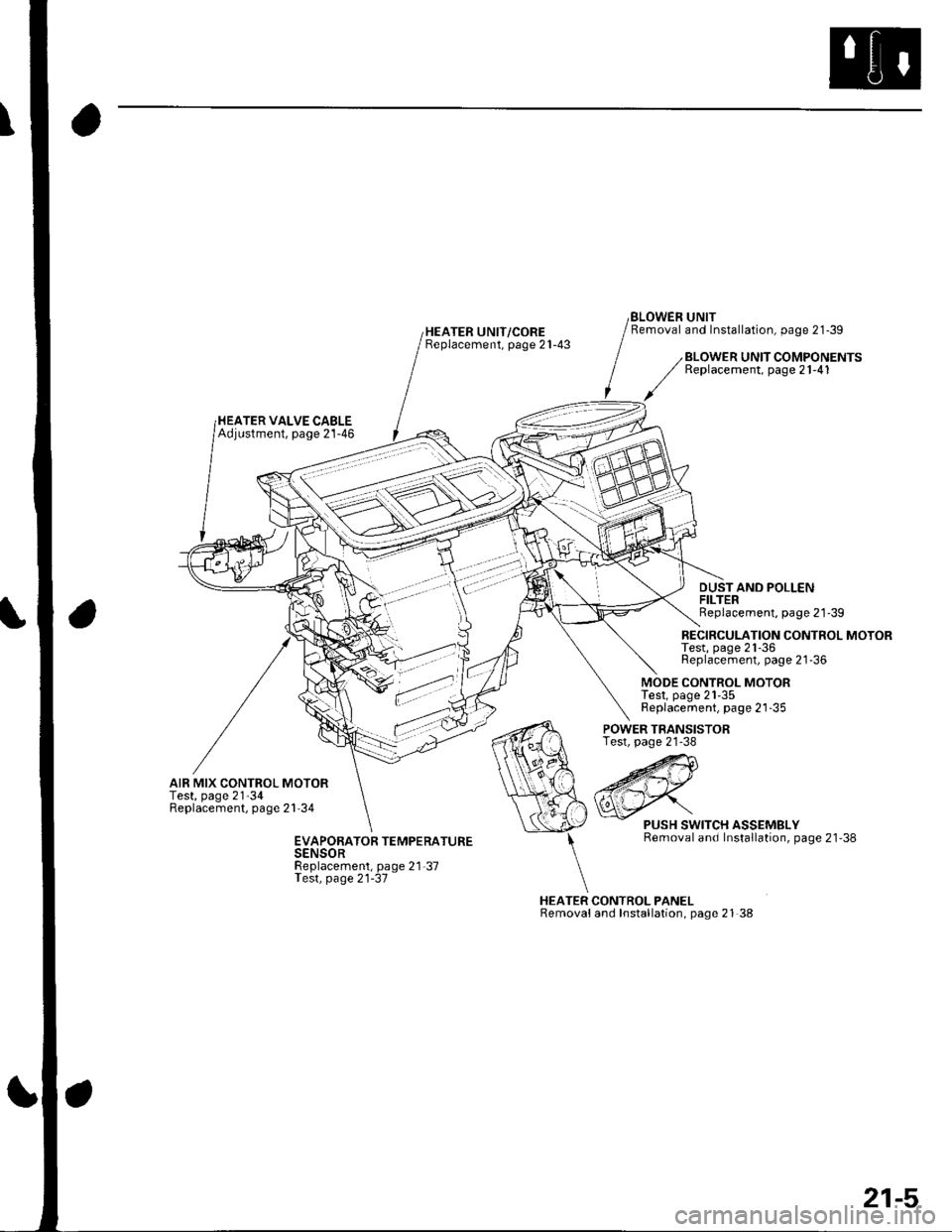
HEATER UNIT/COREBeplacement, page 21-43
BLOWEN UNITRemoval and Installation, page 21-39
HEATER VALVE CABLEAdjustment, page 21-46
BLOWER UNIT COMPONENTSReplacement, page 21-41
DUSTAND POLLENFILTERReplacement, page 21'39
RECIRCULATION CONTROL MOTORTest, page 21-36Replacement, page 21-36
MODE CONTROL MOTORTest, page 21-35Replacement, page 21-35
AIR MIX CONTROL MOTORTest, page 21'34Replacement, page 21'34
POWER TRANSISTORTest, page 21-38
HEATER CONTROL PANELRemovaland Installation, page 21 38
PUSH SWITCH ASSEMBLYRemoval and Installation, page 21'38EVAPORATOR TEMPERATURESENSORReplacement, page 21-37Test, page 21-37
21-5
Page 781 of 1139
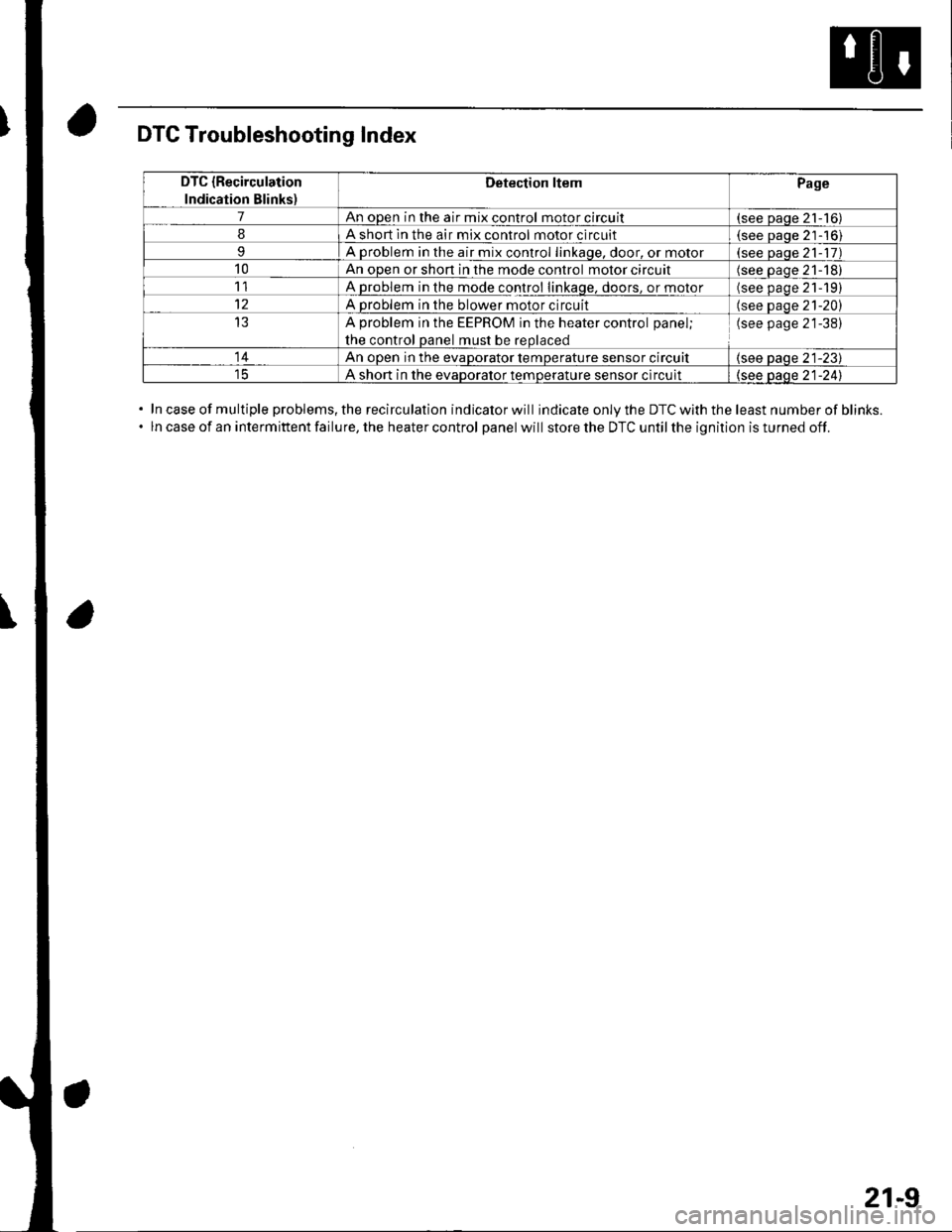
DTC Troubleshooting Index
In case of multiple problems, the recirculation indicator will indicate only the DTC with the least number of blinks.
ln case of an intermittent failure, the heater control panel will store the DTC until the ignition is turned off.
DTC {Recirculation
Indication Blinks)
Detection ltemPage
7An open in the air mix control motor circuit(see paqe 21-16)
8A short ln the air mix control motor circuit(see Daoe 21-'16)
9A problem in the air mix control linkaqe, door, or motor(see paqe 21- 17)
10An open or shon in the mode control motor circuit(see oaqe 21-18)
11A problem in the mode control linkage, doors, or motor(see paqe 21191
12A problem in the blower motor circuit(see paqe 21-20)
13A problem in the EEPROM in the heater control panel;
the control oanel must be reolaced
(see page 21-38)
14An ooen in the evaDorator temDerature sensor circuit(see paqe 21-23)
A short in the evaDoralor temoerature sensor circuit(see oaqe 21-241
21-9
Page 783 of 1139
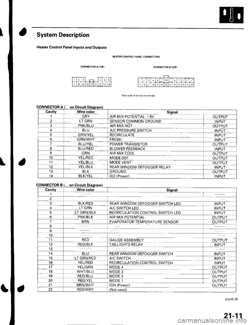
System Description
Heater Control Panel Inputs and Outputs
CONNECTOR A {r/rP)
CONNECTOR
CONNECTOR
HEATER CONTFOL PANEL CONNECIORS
CONNECTOR B (22P)
W re s de oitema eterm nals
Cavity Wire color_| \ln YAIR MIX POTENTIAL +5V
Sional
OUTPUT2LT GRNSENSOR COMMON GROUNDINPUT3PNK/BLUAIR MIX HOTOUTPUTBLUA,/C PRESSURE SWITCHINPUT5GRNA/ELRECIRCULATEINPUT6GRNA/VHTFRESHINPUT7BLUI/ELPOWER TRANSISTOROUTPUT8BLU/REDBLOWER FEEDBACKINPUTIGRNAIR MIX COOLOUTPUT10YEL/REDMODE DEFOUTPUT11. YEVBTU
YEL/BLK
MODE VENT
REAR WINDOW DEFOGGER RELAY
OUTPUT
INPUTBLKGROUNDOUTPUT14B LK/YELlG2 (Power)INPUT
Bon
CavityWire colorSiqnal1--T
2
3BLIVREDREAR WINDOW DEFOGGER SWITCH LEDINPUT
4LT GRNA./C SWITCH LEDINPUT
5LT GRN/BLKRECIRCULATION CONTROL SWITCH LEDINPUT
6PNVBLKAIR MIX POTENTIALOUTPUT
7BRNEVAPORATOR TEIMPERATURE SENSOROUTPUT
8
9
10
GAUGE ASSEMBLYal' 'TDr ri11RED
RED/BLKTAILLIGHTS RELAYINPUT
14BLUREAR WINDOW DEFOGGER SWITCHINPUTicLT GRN/REDA/C SWITCHINPUT16YEVREDRECIRCULATION CONTROL SWITCHINPUT17YEUGRNMODE 4OUTPUT18WHT/BLUMODE 3OUTPUT19RED/BLUMODE 2OUTPUT20RED/YELMODE 1OUTPUTBRN^,^/HTIGN (PowedOUTPUT22R E DA/r'HT(Not used)
(cont'd)
21-11
Page 784 of 1139
Heating and Air Gonditioning
System Description (cont'dl
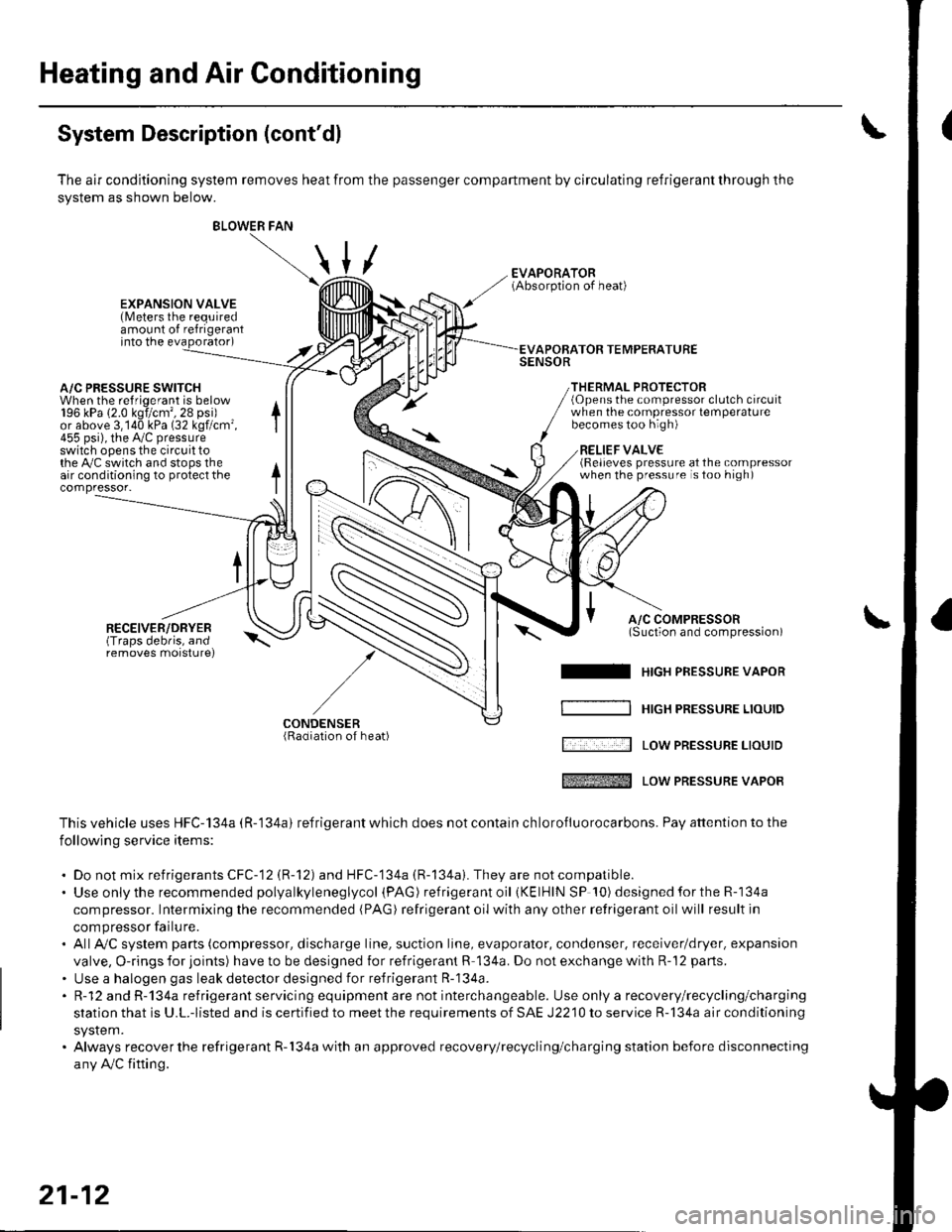
The air conditioning system removes heat from the passenger compartment by circulating refrigerant through the
system as shown below.
/
BLOWER FAN
\
\,u
EXPANSION VALVE(Meters the requiredamount of refrigerantinto the evaporator)
A/C PRESSURE SWITCHWhen the refriqerant is below196 kPa (2.0 kgi/cm',28 psi)or above 3,140 kPa (32 kgf/cm'455 psi), the Py'c pressureswitch opens the circuit tothe Py'C switch and stops theair conditioning to protect thecompressor-
RECEIVER/DRYER(Traps debris, andremoves morsturel
APOBATOR TEMPERATURESENSOR
THERMAL PROTECTOR(Opens the compressor clutch circuitwhen the compressot temperaturebecomes too high)
RELIEF VALVE(Relieves pressure at the compressorwhen the pressure is too high)
A/C COMPRESSOR(Suction and comoression)\-^
I HrcH PRESSURE vAPoR
[ '.... -:--l Low PREsSUBE LrourD
tffi Low PREssURE vAPoR
This vehicle uses HFC-134a (R-'134a) refrigerant which does not contain ch lorofluorocarbons. Pay attention to the
following service items:
. Do not mix refrigerants CFC-12 (R-12) and HFC-134a (R-134a). They are notcompatible.. Use onlythe recommended polyalkyleneglycol (PAG ) refrigera nt oil (KElHlN SP '!0) designedfortheR-134a
compressor. Intermixing the recommended (PAG) refrigerant oil with any other retrigerant oil will result in
compressor failu re.. AllAy'C system parts (compressor, discharge line, suction line, evaporator, condenser, receiver/dryer. expansion
valve, O-rings for joints) have to be designed for refrigerant R 134a. Do not exchange with R-'12 parts.
. Use a halogen gas leak detector designed for refrigerant R-134a.. R-12 and R-134a refrigerant servicing equipment are not interchangeable. Use only a recovery/recycling/charging
station that is U.L.-listed and is certified to meet the requirements of SAE J2210 to service R-134a air conditioning
system.. Always recover the refrigerant R-134a with an approved recovery/recycling/charging station before disconnecting
any Ay'C fifting.
/-
CONDENSER(Radiation of heat)
21-12
Page 786 of 1139
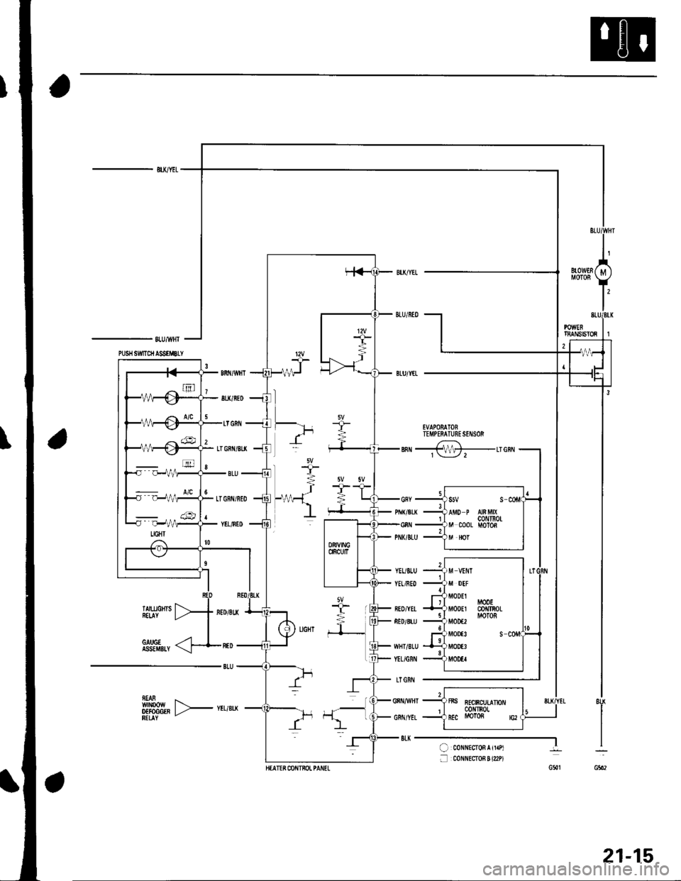
- BU/YEL
-8lU/wH'I
EVAPORATOBTEMPERATUNESENSOR
sn 4-Lrenil
ffftH,, F*u,*
YEUBLU
YEL/NED
BED/YEI
RED/8LU
WHT/8LU
YEL/GRN
LTGRI'l
GNNMHT
GRN/YEL
8LK--..-...-l( coNNEcroFrir.Pt
f mxr{EcroB ! {2P)G5'1
8U
I
G602
m
::-:::: ., . a/c
M DEF
MODEl
Mq)EI
M00€2
M00t3
MOOE3
MOOEI
M00lco TnoLMOTOS
s
21-15
Page 794 of 1139
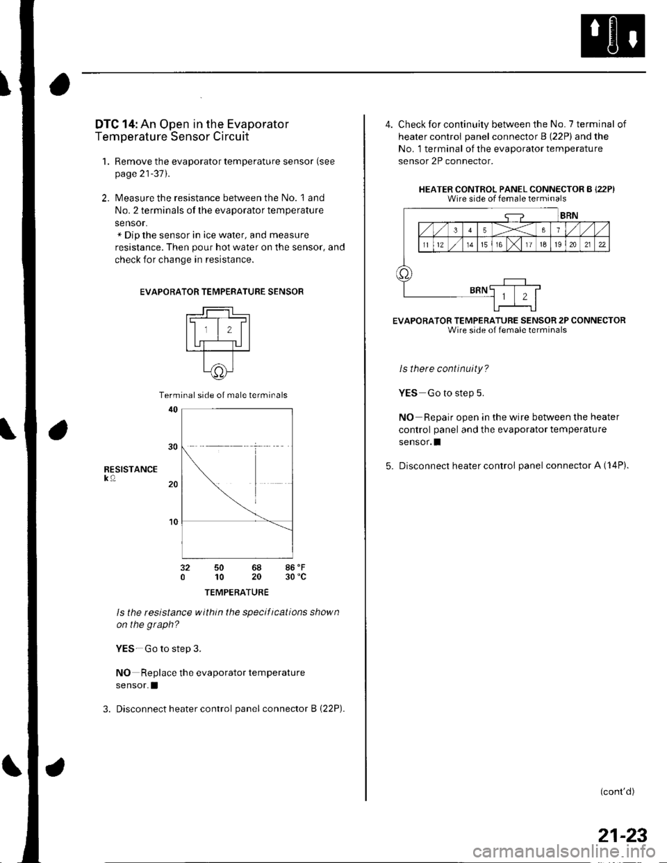
DTC 14: An Open in the Evaporator
Temperature Sensor Circuit
1. Remove the evaporator temperature sensor (see
page 21-37).
2. Measure the resistance between the No. l and
No. 2 terminals of the evaporator temperature
sensor.x Dip the sensor in ice water, and measure
resistance. Then pour hot water on the sensor, and
check for change in resistance.
EVAPORA
RESISTANCEk0
TOR TEMPERATURE SENSOR
t-lll#l
ll,l,llI UT-TU I---r---T--
t^11c))-l\9/
50 6810 20
TEMPERATURE
ls the tesistance within the specifications shown
on the graph?
YES-Go to step 3.
NO Replace the evaporator temperature
sensor.I
3. Disconnect heater control panel connector B {22P).
86'F30 'c
Terminal side of male terminals
4. Check for continuity between the No. 7 terminal of
heater control panel connector B (22P) and the
No. 1 terminal of the evaporalor temperature
sensor 2P connector.
HEATER CONTROL PANEL CONNECTOR B {22P)Wire side of female terminals
EVAPORATOR TEMPERATURE SENSOR 2P CONNECTORWire side of female terminals
ls there continuity?
YES Go to step 5.
NO Repair open in the wire between the heater
control panel and the evaporator temperature
sensor.I
5. Disconnect heater control panel connector A (14P).
(cont'd)
21-23
Page 795 of 1139
Heating and Air Gonditioning
\
DTC Troubleshooting {cont'd)
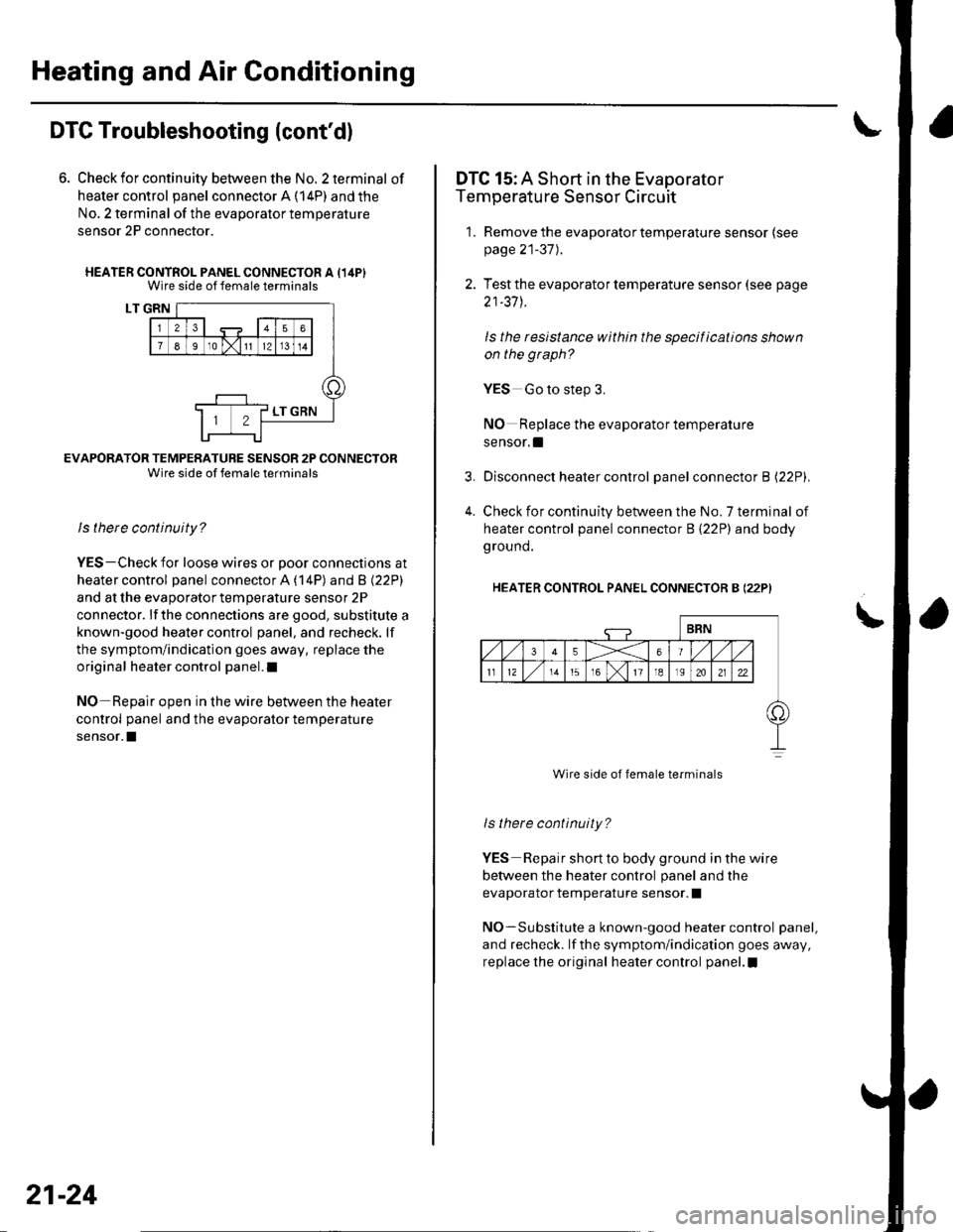
6. Check for continuity between the No. 2 terminal of
heater control panel connector A (14P) and the
No, 2 terminal of the evaporalor temperature
sensor 2P connector.
HEATER CONTROL PANEL CONNECTOR A {14PIWire side of female terminals
LT GRN
EVAFORATOR TEMPERATURE SENSOR 2P CONNECTORWire side of female terminals
ls there continuity?
YES-Check for loose wires or Door connections at
heater control panel connector A ('l4P) and B l22Pl
and at the evaporator temperature sensor 2P
connector. lf the connections are good, substitute a
known-good heater control panel, and recheck. lf
the symptom/indication goes away, replace the
original heater control panel.l
NO Reoair ooen in the wire between the heater
control panel and the evaporator temperature
sensor.I
21-24
4.
DTC 15: A Short in the Evaporator
Temperature Sensor Circuit
1. Remove the evaporator temperature sensor (see
page 21-37).
2. Test the evaporator temperature sensor (see page
21-37 J.
ls the resistance within the specifications shown
on the graph?
YES Go to step 3.
NO Replace the evaporator temperature
sensor. !
Disconnect heater control panel connector B l22Pl.
Check for continuity between the No. 7 terminal of
heater control panel connector B {22P) and body
ground.
HEATER CONTROL PANEL CONNECTOR B (22P)
Wire side of female terminals
ls there continuity?
YES Repair short to body ground in the wire
betvveen the heater control panel and the
evaporator temperature sensor. I
NO-Substitute a known-good heater control panel,
and recheck. lf the symptom/indication goes away,
replace the original heater control panel.I
Page 801 of 1139
Heating and Air Conditioning
Radiator and Condenser Fans
Common
(cont'dl
Circuit Troubleshooting
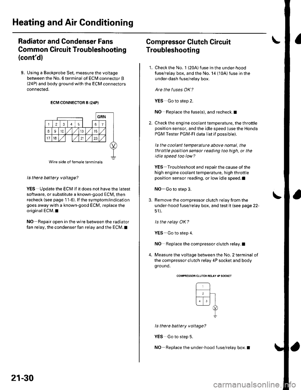
9. Using a Backprobe Set, measure the voltage
between the No. 6 terminal of ECN4 connector B
{24P) and body ground with the ECM connectors
connecteo.
ECM CONNECTOR B {24P}
ls there battery voltage?
YES UDdate the ECM if it does not have the latest
so{tware, or substitute a known-good ECM, then
recheck (see page 11-6). lf the symptom/indication
goes away with a known-good ECM, replace the
original ECM.I
NO Repair open in the wire between the radiator
fan relay, the condenser fan relay and the ECM. t
Wire side of female terminals
21-30
Compressor Clutch Circuit
Troubleshooting
1. Check the No. 1 (20A) fuse in the under-hood
fuse/relay box, and the No. 14 {10A)fuse in the
under-dash fuse/relay box.
Are the tuses OK?
YES Go to step 2.
NO Replace the fuse(s), and recheck.I
2. Check the engine coolant temperature, the throttleposition sensor, and the idle speed (use the Honda
PGM Tester PGM-Fl data list if possible).
ls the coolant temperaturc above nomal, the
throttle position sensor rcading too high, or the
idle speed too low?
YES Troubleshoot and repair the cause of the
high engine coolant temperature, high throttle
position sensor reading, or low idle speed.l
NO-Go to step 3.
3. Remove the compressor clutch relay from the
under-hood fuse/relay box, and test it (see page 22-
51 ).
ls the relay OK?
YES Go to step 4.
NO Replace the compressor clutch relay.I
4. Measure the voltage between the No. 2 terminal of
the compressor clutch relay 4P socket and body
ground.
\
COMPfiESSON CLUTCH BELAY 'P SOCKET
ls there battery voltage?
YES Go to step 5.
NO Replace the under-hood fuse/relay box.I
Page 808 of 1139
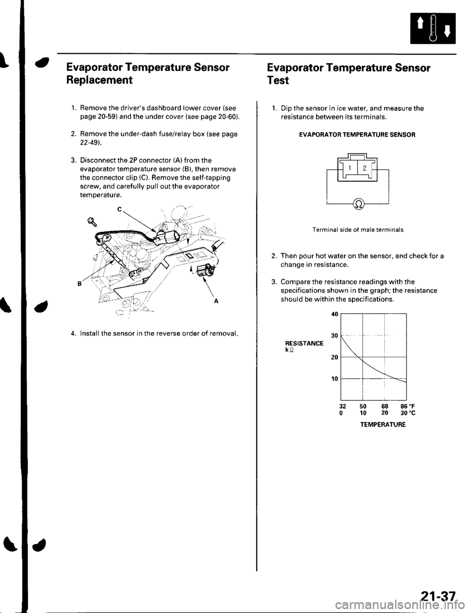
Evaporator Temperature Sensor
Replacement
1.Remove the driver's dashboard lower cover (see
page 20-59) and the under cover (see page 20-60).
Remove the under-dash fuse/relay box (see page
22-491.
Disconnect the 2P connector (A) from the
evaporator temperature sensor (B), then remove
the connector clip (C). Remove the self-tapping
screw, and carefully pull out the evaporator
temperature.
4. Install the sensor in the reverse order of removal,
Evaporator Temperature Sensor
Test
l. Dip the sensor in ice water, and measure the
resistance between its terminals
EVAPORATOR TEMPERATURE SENSOR
2.
3.
Terminal side ol male terminals
Then pour hot water on the sensor, and check {or a
change in resistance.
Compare the resistance readings with the
specifications shown in the graph; the resistance
should be within the specifications
RESISTANCEk9
t0
32050 68 86 'F
10 20 30'c
TEMPERATURE
21-37
Page 815 of 1139
Heating and Air Conditioning
Heater Unit/Core Replacement (cont'd)
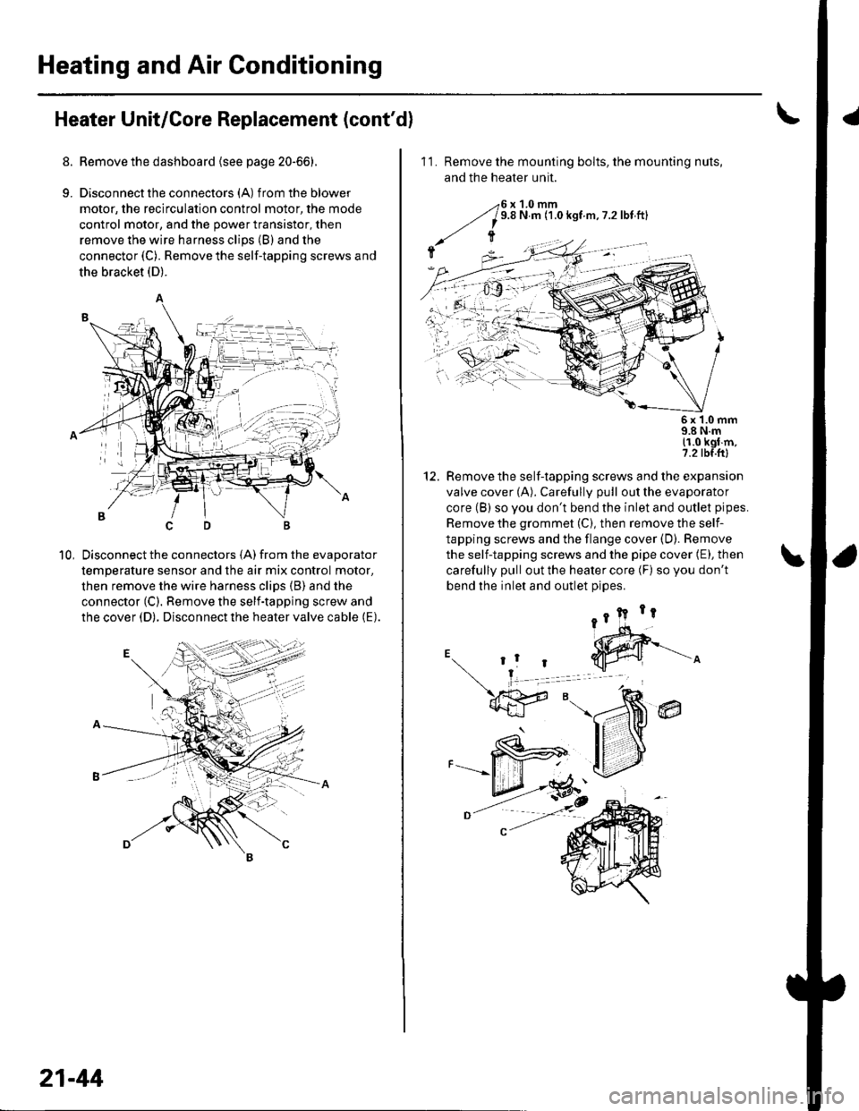
8. Remove the dashboard {see page 20-66).
9. Disconnectthe connectors (A) from the blower
motor, the recirculation control motor, the mode
control motor, and the power transistor, then
remove the wire harness clips (B) and the
connector (C). Remove the self-tapping screws and
the bracket (D).
Disconnect the connectors (A) from the evaporator
temperature sensor and the air mix control motor,
then remove the wire harness clips (B) and the
connector (C). Remove the self-tapping screw and
the cover (D). Disconnect the heater valve cable (E).
10,
7t,
21-44
11. Remove the mounting bolts, the mounting nuts,
and the heater unit.
Remove the self-tapping screws and the expansion
valve cover (A). Carefully pull out the evaporator
core (B) so you don't bend the inlet and outlet pipes.
Remove the grommet (C), then remove the self-
tapping screws and the flange cover (D). Bemove
the self-tapping screws and the pipe cover (E), then
carefully pull out the heater core (F) so you don't
bend the inlet and outlet oioes.
@
5x 1.0 mm9.8 N.m11.0 kgl m,7.2 tbf.ftl
12.