sensor HONDA CIVIC 2002 7.G Workshop Manual
[x] Cancel search | Manufacturer: HONDA, Model Year: 2002, Model line: CIVIC, Model: HONDA CIVIC 2002 7.GPages: 1139, PDF Size: 28.19 MB
Page 1020 of 1139
sRs
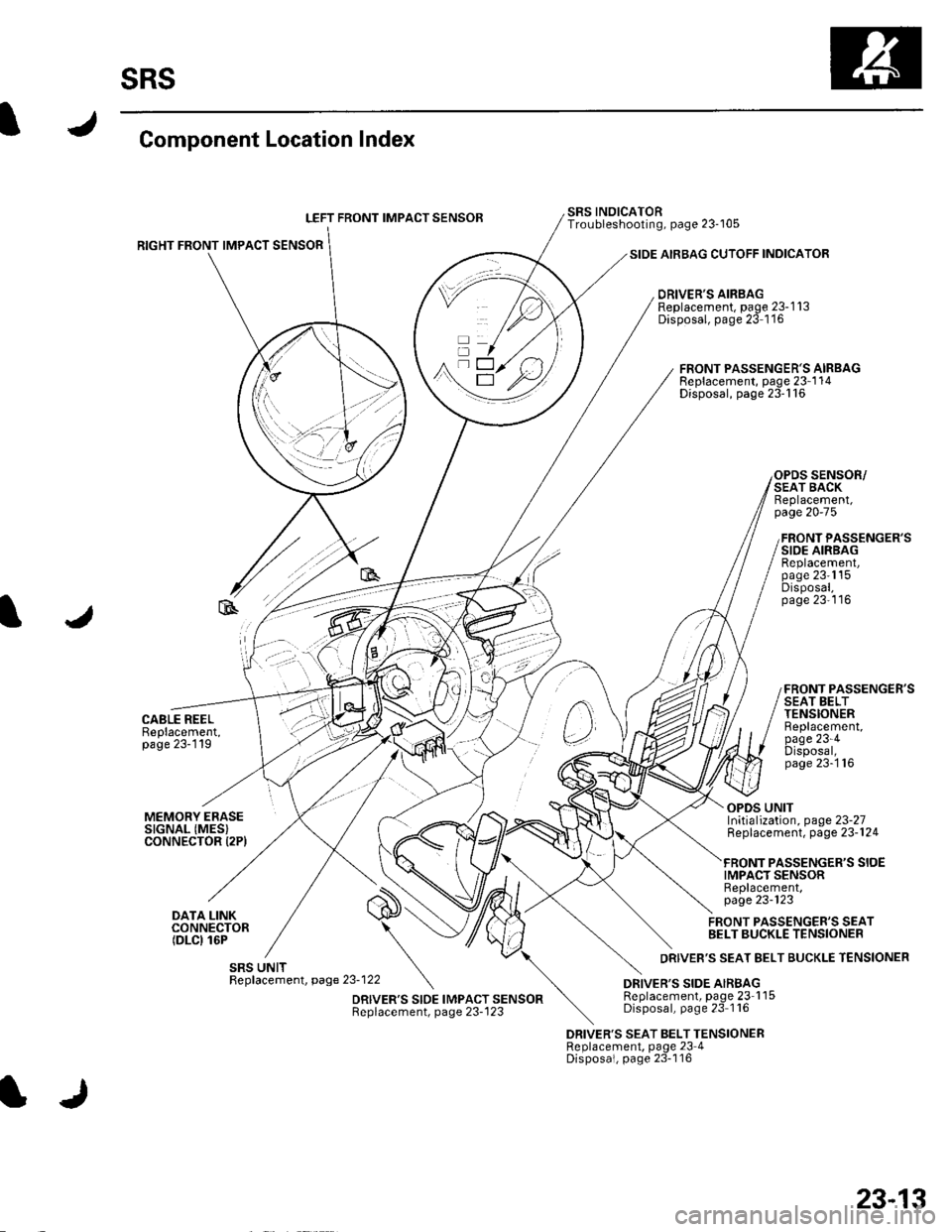
Component Location Index
LEFT FRONT IMPACT SENSOB
RIGHT FRONT IMPACT SENSOR
CABLE REELBeplacement,page 23-119
SIDE AIRBAG CUTOFF INDICATOR
DRIVER'S AIRBAGReplacement, page 23-1 13Disposal, page 23 1'16
SRS INOICATORTroubleshooting, page 23-105
FRONT PASSENGER'S AIRBAGReplacement, page 23-1 14Disposal, page 23'116
SENSOR/SEAT BACKReplacement,page 20-75
FRONT PASSENGER'SSIDE AIRBAGReplacement,page 23'1'15Disposal,page 23'116
FRONT PASSENGER'SSEAT BELTTENSIONERBeplacement,page 23-4Disposal,page 23-'116
MEMORY ERASESIGNAL (MES}CONNECTOR I2PI
DATA LINKCONNECTOR(DLCI 16P
OPDS UNITInitialization, page 23-27Replacement, page 23-124
PASSENGER'S SIOEIMPACT SENSORReplacement,page 23-123
FRONT PASSENGER'S SEATBELT BUCKLE TENSIONER
DRIVER'S SEAT BELT TENSIONERReplacement, page 23 4Disposal, page 23-116
23-13
Page 1023 of 1139
sRs
Precautions and Procedures {cont'dl
SRS Unit, Front lmpact Sensors, and Side
lmpact Sensors
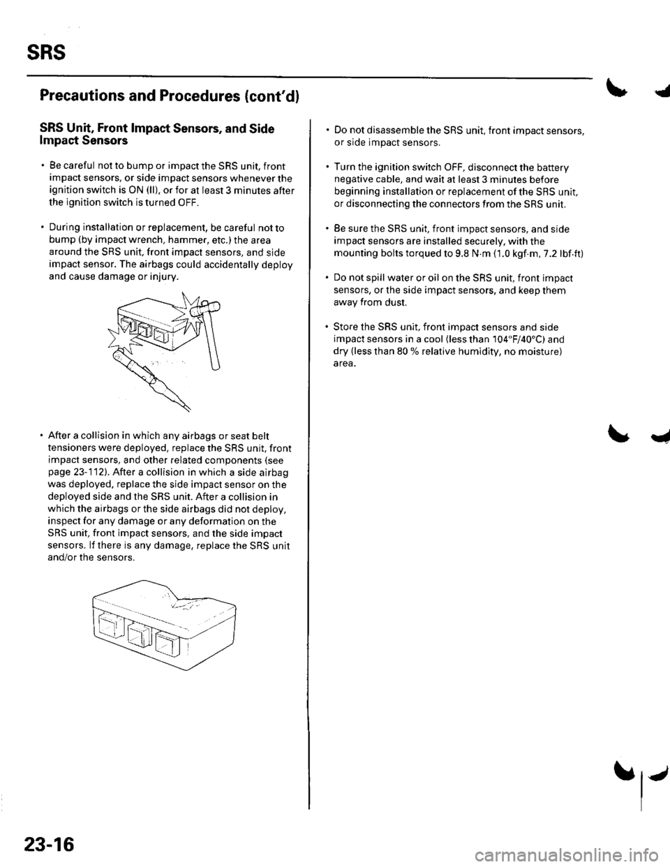
. Be careful not to bump or impact the SRS unit, front
impact sensors, or side impact sensors whenever the
ignition switch is ON (ll), or for at least 3 minules after
the ignition switch is turned OFF.
. During installation orreplacement, be careful notto
bump (by impact wrench, hammer, etc.) the area
around the SRS unit, front impact sensors, and sjde
impact sensor. The airbags could accidentally deploy
and cause damage or injury.
After a collision in which any airbags or seat belt
tensioners were deployed. replace the SRS unit, front
impact sensors, and other related components (see
page 23-112). After a collision in which a side airbag
was deployed. replace the side impact sensor on the
deployed side and the SRS unit. After a collision in
which the airbags or the side airbags did not deploy,
inspect for any damage or any deformation on the
SRS unit, front impact sensors, and the side impact
sensors. lf there is any damage, replace the SRS unit
and/or the sensors.
23-16
.j
. Do not disassemble the SRS unit, front impact sensors,
or side impact sensors.
. Turn the ignition switch OFF, disconnect the battery
negative cable, and wait at least 3 minules before
beginning installation or replacement of the SBS unit,
or disconnecting the connectors from the SRS unit.
. Be sure the SRS unit, front impact sensors, and side
impact sensors are installed securely. with the
mounting bolts torqued to 9.8 N.m (1.0 kgf.m,7.2 lbf.ft)
. Do not spill wateroroil on the SRS unit, front impact
sensors, or the side impact sensors, and keep them
away from dust.
. Store the SRS unit, front imDact sensors and side
impact sensors in a cool (less than 104"F/40'C) and
dry (less than 80 % relative humidity, no moisture)
area.
I
Page 1027 of 1139
sRs
Precautions and Procedures (cont'dl
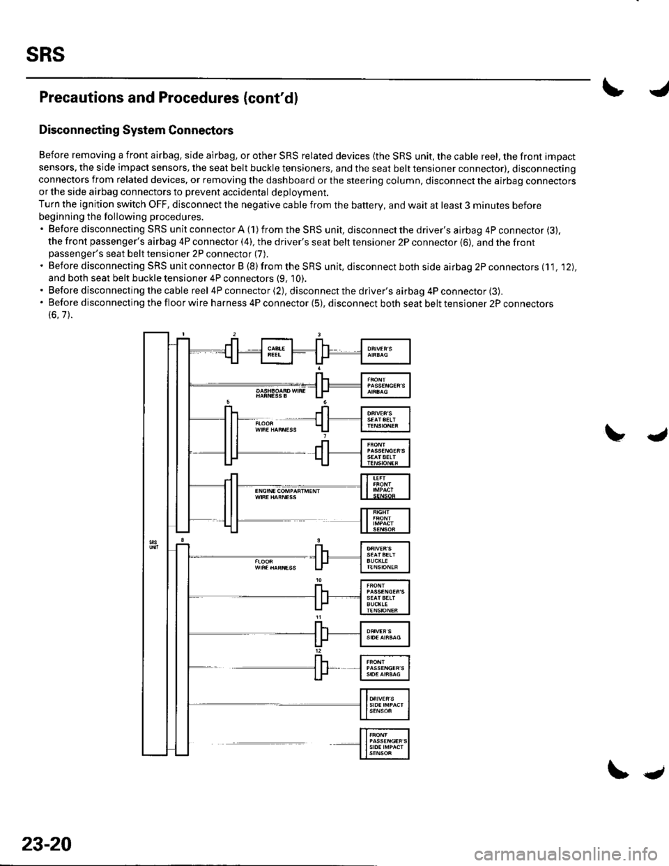
Disconnecting System Connectors
Before removing a front airbag. side airbag, or other SRS related devices {the SRS unit, the cable reel, the front impact
sensors, the side impact sensors, the seat belt buckle tensioners, and the seat belt tensioner connector), disconnectingconnectors from related devices, or removing the dashboard or the steering column, disconnect the airbag connectorsor the side airbag connectors to prevent accidental deploVment.
Turn the ignition switch OFF, disconnect the negative cable from the battery, and wait at least 3 minutes before
beginning the following procedures.'BeforedisconnectingSRSunitconnectorA(1)fromtheSRSunit,disconnectthedriver'sairbag4Pconnector(3).
the front passenger's airbag 4P connector (4), the driver's seat belt tensioner 2P connector (6), and the frontpassenger's seat belt tensioner 2P connector (7).
. Before disconnecting SRS unit connector B (8) from the SRS unit, disconnect both side airbag 2P connectors (11. '12),
and both seat belt buckle tensioner 4P connectors (9, 10).. Before disconnecting the cable reel 4P connector (2), disconnect the driver's airbag 4P connector (3).'Beforedisconnectingthefloorwireharness4Pconnector(5),disconnectbothseatbelttensioner2Pconnectors
(6.7).
23-20
\.
Page 1036 of 1139
IJ
lr
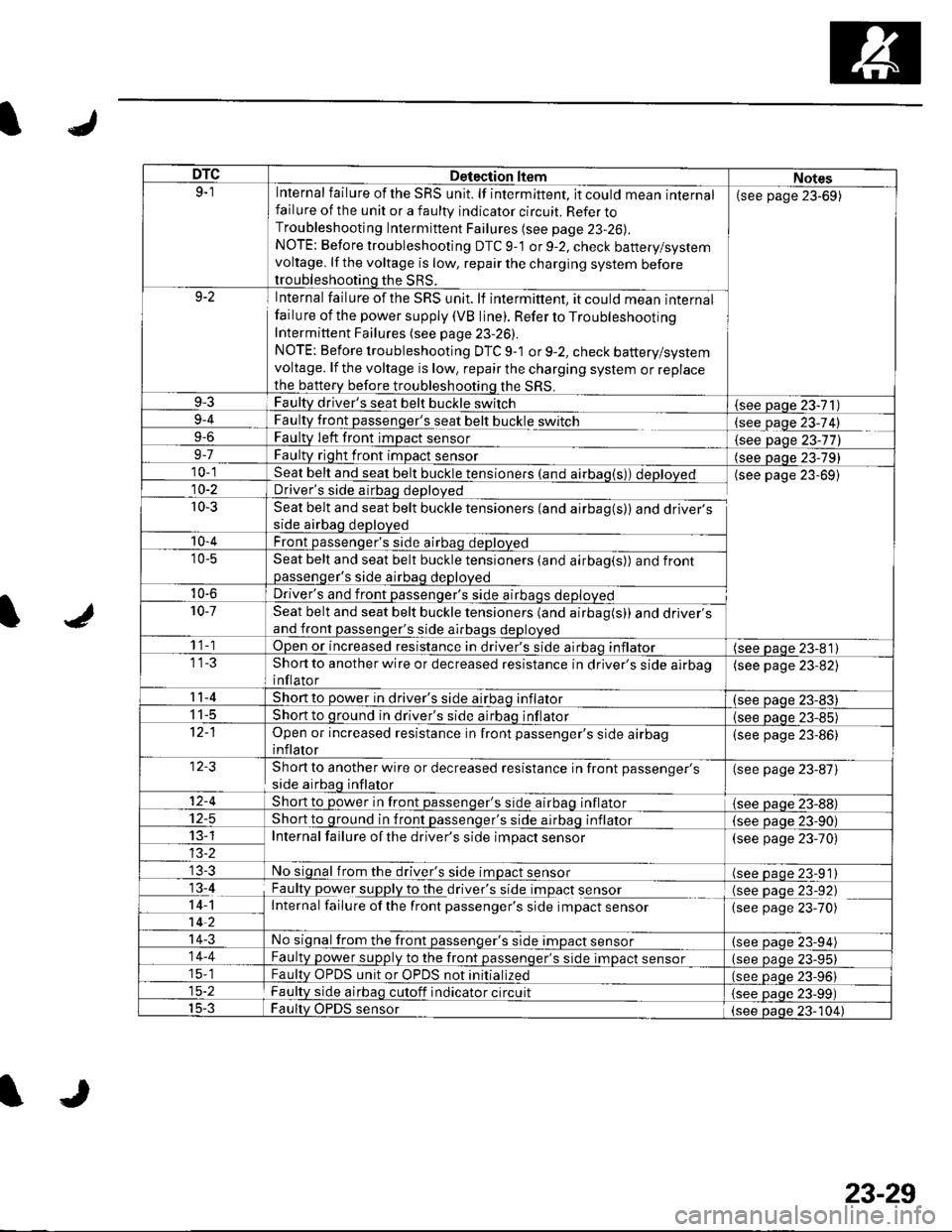
DTCDetection ltemNotes9-1Internal failure of the SRS unit. lf intermittent, it could mean internalfailure of the unit or a faulty indicator circuit. Refer toTroubleshooting Intermittent Failures (see page 23-26).
NOTE: Before troubleshooting DTC 9-1 or 9-2, check battery/systemvoltage. lf the voltage is low, repair the charging system beforetroubleshooting the SRS.
(see page 23-69)
9-2Internal failure of the SRS unit. lf intermittent, it could mean internalfailu re of the power supply (VB line). Refer to TroubleshootingIntermittent Failures (see page 23-26).
NOTE: Before troubleshooting DTC 9-1 or 9-2, check battery/systemvoltage. lf the voltage is low, repair the charging system or replacethe b€ttery before troubleshooting the SRS.
9-3Faulty driver's seat belt buckle switch(see Daqe 23-71)9-4
9-6
FaultLtglt passenger's seat belt buckle switch
Faulty Ieft front imDact sensorlgqgfage 23-74)
{see Daqe 23-77)9-7Faulty right front impact sensor(see paqe 23-79)10-1Seat belt and seat belt buckle tensioners (and airbag(s)) deployedDriver's side airbag deployed
Seat belt and seat belt buckle tensioners (and airbag(s)) and driver'sside airbag deployed
Front passenqer's side airbao deDloved
(see page 23-69)10-2
r0-3
'10-4
'10-5Seat belt and seat belt buckle tensioners (and airbag(s)) and frontpassenqer's side airbaq deDloved
10-6Driver's and front passenqer's side al10-7Seat belt and seat belt buckle tensioners (and airbag(s)) and driver'sand front passenger's side airbags deployed
1 1-1Open or increased resistance in driver's side airbao inflator(see paqe 23-81)Short to another wire or decreased resistance in driver's side airbaoinflator
(see page 23-82)
11-4Short to power in driver's side airbaq inflator(see oaqe 23-83)I t-5Short to ground in driver's side airbaq inflator{see paqe 23-85)Open or increased resistance in front passenger's side airbaginflator
(see page 23-86)
Short to another wire or decreased resistance in front passenger's
side airbag inflator
(see page 23-87)
12-4Short to power in front passenqer's side airbaq inflator{see Daqe zJ-uu}I z-5Short to ground in front passenger's side airbaq inflator(see oaqe 23-90)13-1Internal failure of the driver's side impact sensor(see page 23-70)
No signal from the driver's side impact sensor(see paqe 23-91)13-4
14-1-7ii,
Faulty power supply to the df,rglllug t Opact s9I99LInternal failure ofthe front passenger's side impact sensor
(see page 23-92)(see page 23-70)
14-3No signal from the front passenger's side impact sensor(see paqe 23-94)14-4Faulty power supply to the front passenqer's side impact sensor(see page 23-95)15-1Faultv OPDS unit or OPDS not initialized(see paqe 23-96115-2Faulty side airbag cutoff indicator circuit(see Daqe 23-99)15-3Faulty OPDS sensor(see oaoe 23-104)
IJ
23-29
Page 1037 of 1139
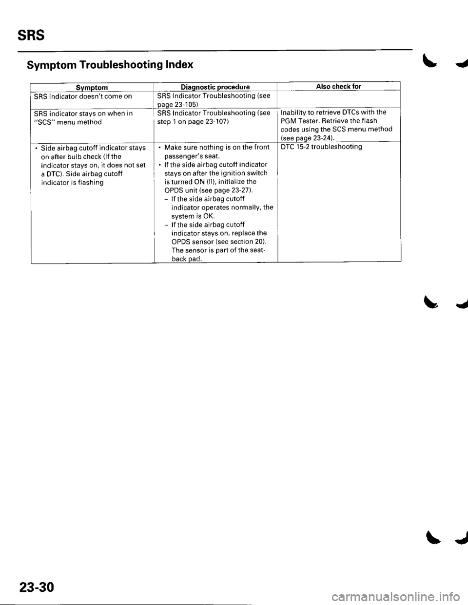
SRS
SymptomDiagnostic procedureAlso check for
SRS indicator doesn't come onSRS Indicator Troubleshooting (see
paoe 23-105)
SRS indicator stays on when in"SCS" menu method
SRS Indicator Troubleshooting (see
step 1 on page 23-107)
Inability to retrieve DTCs with the
PGM Tester. Retrieve the flash
codes using the SCS menu method
(see page 23-24).
Slde airbag cutoff indicator stays
on after bulb check (lfthe
indicator stays on, it does not set
a DTC). Side airbag cutoff
indicator is flashing
. Make sure nothing is on the fronl
passenger's seat.. lf the side airbag cutoff indicator
stays on after the ignition switch
is turned ON (ll), initialize the
OPDS unit (see page 23-271.- lf the side airbag cutoff
indicator operates normallY, the
system is OK.- lf the side airbag cutoff
indicator stays on, replace the
uFU5 SenSOr {See SeCrOn ZUl.
The sensor is part of the seat-
back Dad.
DTC 15-2 troubleshooting
Symptom Troubleshooting Index\4
trJ
23-30
\J
Page 1038 of 1139
ISystem Description
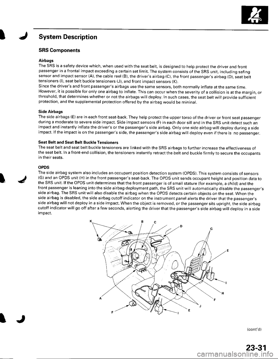
SRS Components
Airbags
The SRS is a safety device which, when used with the seat belt, is designed to help protect the driver and frontpassenger in a frontal impact exceeding a certain set limit. The system consists ofthe SRS unit, including safingsensor and impact sensor (A), the cable reel (B), the driver's airbag (C), the front passenger,s airbag (D). seat belttensioners (l), seat belt buckle tensioners (J), and front impact sensors (K).
Since the driver's and front passenger's airbags use the same sensors, both normally inflate at the same ttme.However, it is possible for only one airbag to inflate. This can occur when the severity of a collision is at the margin, orthreshold, that determines whether or not the airbags will deploy. In such cases, the seat belt will provide sufficientprotection, and the supplemental protection offered by the airbag would be mininal.
Side Airbags
The side airbags (E) are in each front seat-back. They help protect the upper torso of the driver or front seat passenger
during a moderate to severe side impact. Side impact sensors (F) in each door sill and in the SRS unit detect such animpact and instantly inflate the driver's or the passenger's side airbag. Only one side airbag will deploy during a sideimpacl. lf the impact is on the passenger's side, the passenger's side airbag will deploy even if there is no passenger.
Seat Belt and Seat Belt Buckle Tensioners
The seat belt and seat belt buckle tensioners are linked with the SRS airbags to further increase the effectiveness ofthe seat belt. ln a front-end collision, the tensioners instantly retract the belt and buckle firmly to secure the occupantsin their seats.
OPDS
The side airbag system also includes an occupant position detection system (OpDS). This system consists of sensors(G)and an OPDS unit (H) in the front passenger's seat-back. The OPDS unit sends occupant heighl and position data tothe SRS unit. lf the OPDS unit determines that the front passenger is of small stature (for example, a child) and thefront passenger is leaning into the side airbag deployment path, the SRS unit will automatically disable the passenger'sside airbag. The SRS unit will also disable the airbag when the OPDS detects certain obiects on the seat. When theside airbag is disabled, the side airbag cutoff indicator on the instrument panel alerts the driver that the passenger'sside airbag will not deploy in a side impact. When the object is removed, or the passenger sits upright, the side airbagcutoff indicator will go off after a few seconds, alerting the driver that the passenger's side airbag will deploy in a sideimDact.
(cont'd)
I
23-31
Page 1039 of 1139
sRs
System Description (cont'dl
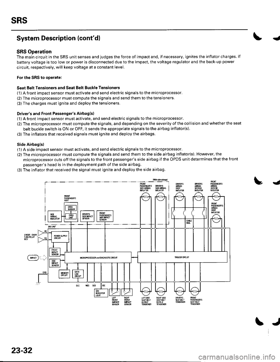
SRS Operation
The main circuit in the SRS unit senses and judges the force of impact and, if necessary. ignites the inflator charges. lf
battery voltage is too low or power is disconnected due to the impact, the voltage regulator and the back-up power
circuit, respectively, will keep voltage at a constant level.
For the SRS to operate:
Seat Belt Tensioners and Seat Belt Buckle Tensioners
(1) A front impact sensor must activate and send electric signals to the microprocessor.
(2) The microprocessor must compute the signals and send them to the tensioners.
(3) The charges must ignite and deploy the tensioners.
Driver's and Front Passenger's Airbagls)
(1) A front impact sensor musl activate. and send electric signals to the microprocessor.
(2) The microprocessor must compute the signals. and depending on the severity of the collision and whether the seat
belt buckle swilch is ON or OFF, it sends the appropriate signals to the airbag inflator(s).
(3) The inflators that received signals must ignite and deploy the airbags.
Side Airbaglsl( 1) A side impact sensor must activate, and send electric signals to the microprocessor.
(2) The microprocessor must compute the signals and send them to the side airbag inflator(s). However, the
microprocessor cuts off the signals to the front passenger's side airbag if the OPDS unit determines that the tront
passenger's head is in the deployment path of the side airbag.
(3) The inflator that received the signal must ignite and deploy the side airbag.
lw$ad..n sl
!J
T'sEcttoJn0mP gsfrlctR S oXrVEr S I9oEAiA$ SOtlr&G I
f'**)r !
23-32
\J
Page 1077 of 1139
SRS
DTC Troubleshooting (cont'd)
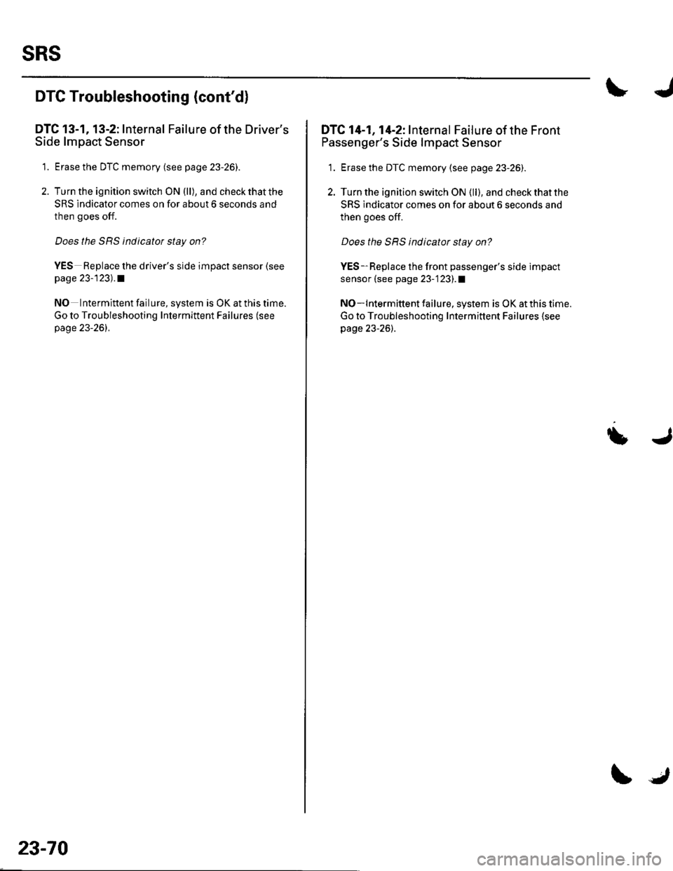
DTC 13-1, 13-2: Internal Failure of the Driver's
Side lmpact Sensor
1. Erase the DTC memory (see p age 23-26).
2. Turn the ignition switch ON (ll), and check that the
SRS indicator comes on for about 6 seconds and
then goes off.
Does the SRS indicatot stay on?
YES Replace the driver's side impact sensor (see
page 23-123) .a
NO Intermittent failure, system is OK at this time.
Go to Troubleshooting Intermittent Failures (see
page 23-261.
23-70
IJ
DTC 14-1, 14-2: Internal Failure ofthe Front
Passenger's Side lmpact Sensor
1. Erase the DTC memory (see page 23-26).
2. Turn the ignition switch ON (ll), and check that the
SRS indicator comes on for about 6 seconds and
then goes off.
Does the SRS indicator stay on?
YES-Replace the front passenger's side impact
sensor (see page 23-123],.1
NO-lntermittent failure, system is OK at this time.
Go to Troubleshooting Intermittent Failures (see
page 23-26).
U
Page 1084 of 1139
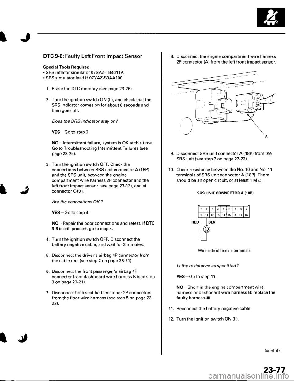
DTC 9-6: Faulty Left Front lmpact Sensor
Special Tools Required. SRS inflator simulator 07SAZ-TB4011A. SRS simulator lead H 07YM-S3AA100
1. Erase the DTC memory (see page 23-26).
2. Turn the ignition switch ON (ll), and check that the
SRS indicator comes on for about 6 seconds and
then goes off.
Does the SRS indicator stay on?
YES-Go to step 3.
NO Intermiftent failure, system is OK at this time.
Go to Troubleshooting Intermittent Failures (see
page 23-26).
3. Turn the ignition switch OFF. Check the
connections between SRS unit connector A (18P)
and the SRS unit. between the engine
compartment wire harness 2P connector and the
left front impact sensor {see page 23-13), and at
connector C401.
Are the connections OK?
YES Go to step 4.
NO-Repair the poor connections and retest. lf DTC
9-6 is still present, go to step 4.
Turn the ignition switch OFF. Disconnect the
battery negative cable. and wait for 3 minutes.
Disconnect the driver's airbag 4P connector from
the cable reel (see step 2 on page 23-21).
Disconnect the front passenger's airbag 4P
connector from dashboard wire harness B {see step
3 on page 23-21).
Disconnect both seat belt tensioner 2P connectors
from the floor wire harness (see step 5 on page 23-
22).
7.
9.
10.
8. Disconnect the engine compartment wire harness
2P connector {A) from the left front impact sensor.
Disconnect SRS unit connector A {18P) from the
SRS unit (see step 7 on page 23-22J.
Check resistance between the No. 10 and No. 11
terminals of SRS unit connector A (18P). There
should be an oDen circuit. or at least 1 M 0 .
SRS UNIT CONNECTOR A (18PI
Wire side of female terminals
ls the resistance as specitied?
YES Go to step 1 1.
NO-Short in the engine companment wire
harness or dashboard wire harness B; replace the
faulty harness.I
Reconnect the battery negative cable.
Turn the ignition switch ON { ll).
{cont'd}
RED
11.
12.
2356789
10tl1Zt315161718
I
T
ILK
23-77
Page 1085 of 1139
sRs
DTC Troubleshooting (cont'dl
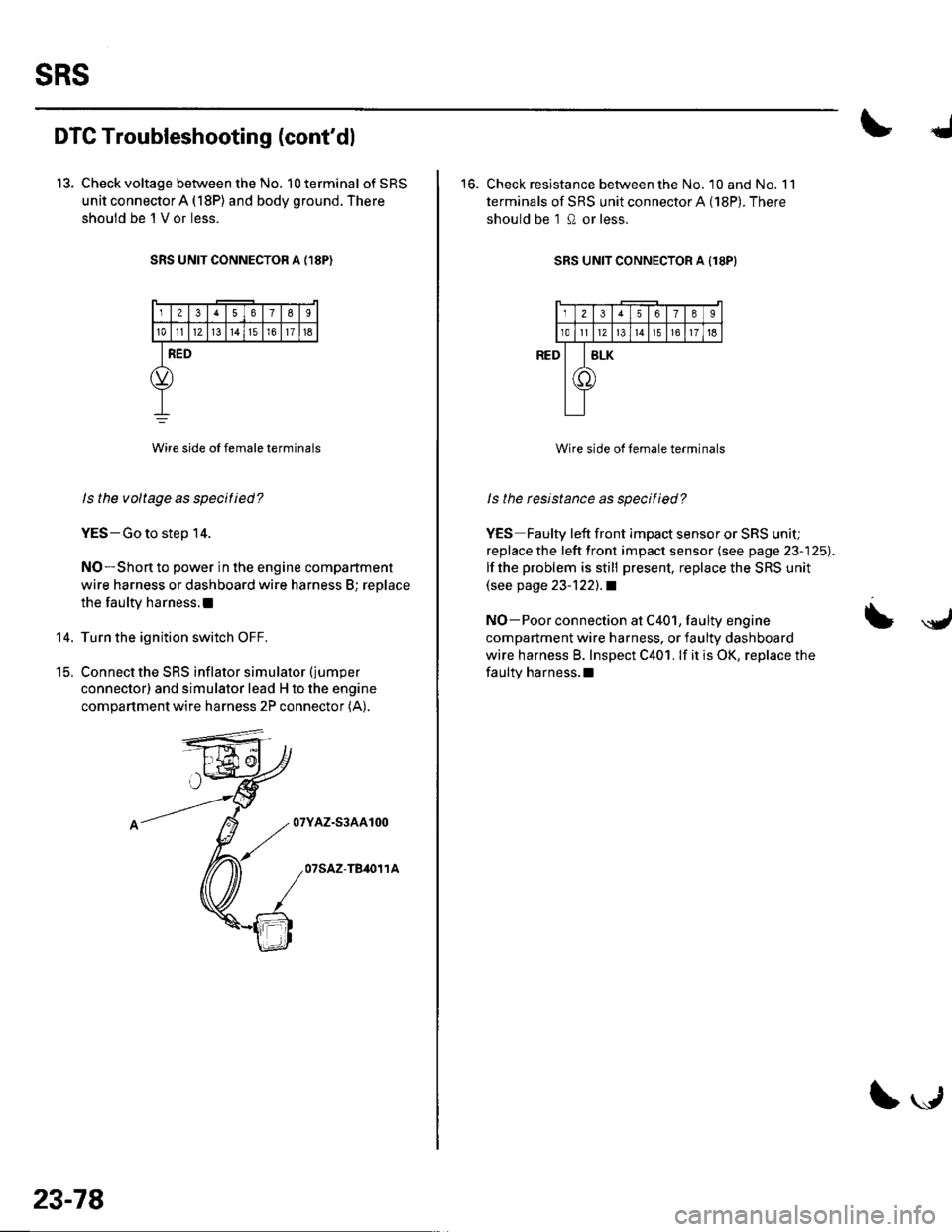
13. Check voltage between the No. 10 terminal of SRS
unit connector A (18P) and body ground. There
shouid be 'l V or less.
SRS UNIT CONNECTOR A {,I8P)
12378I
101112l3t4151611t6
RED
Wire side oI female terminals
ls the voltage as specitied?
YES-Go to step 14.
NO-Short to power in the engine compartment
wire harness or dashboard wire harness B; replace
the faulty harness.l
Turn the ignition switch OFF.
Connect the SRS inflator simulator (jumper
connector) and simulator lead H to the engine
compartment wire harness 2P connector (A).
07YAZ-S3AA100
07SAZ-TB,O11A
14.
t5.
23-78
\."r1
16. Check resistance between the No. 10 and No. 11
terminals of SRS unit connector A (18P). There
should be 1 0 or less.
SRS UNIT CONNECTOR A Il8PI
Wire side of female terminals
ls the rcsistance as specified?
YES Faulty left front impact sensor or SRS unit;
replace the left front impact sensor (see page 23-125).
lf the problem is still present, replace the SRS unit(see page 23-122).1
NO-Poor connection at C401, faulty engine
compartment wire harness, or faulty dashboard
wire harness B. Inspect C401. lf it is OK, replace the
faulty harness.l
= \y,