11-4 HONDA CIVIC 2002 7.G User Guide
[x] Cancel search | Manufacturer: HONDA, Model Year: 2002, Model line: CIVIC, Model: HONDA CIVIC 2002 7.GPages: 1139, PDF Size: 28.19 MB
Page 252 of 1139
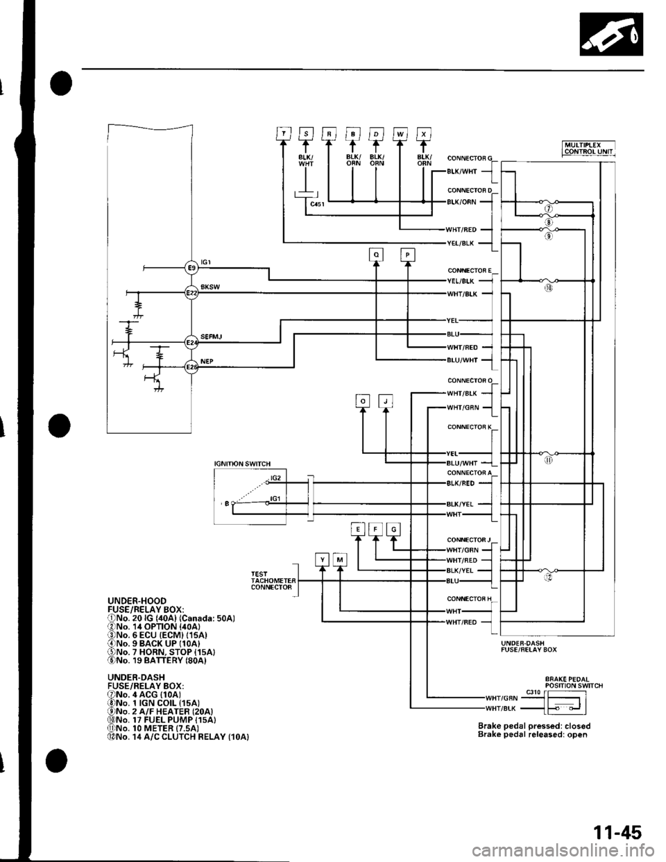
""rr"a* JIr''lHr/cnN 1
CONNECTOR E
CONNECTOi K
CONNECTOFJ/GRN
IGNITIONSWITCH
lG2
'I
TESTTACHOMETERCONNECTO8
UNDER.HOOD
UNDER.DASHFUSE/RELAY BOX:
UNDER.DASHFUSE/FELAY BOX
Brake pedal pressed: closedBrake pedal releasedr open
POStTtON SWTTCH
,or"-9J3{51re* _{F "_.rl
4 ACG (1oAt1 tGN CO|L t15A)2 A/F HEATER {2OA)17 FUEL PUMP I15A}1O METER {7.5AI14 A/C CLUTCH RELAY {1OA}
11-45
Page 253 of 1139
Fuel and Emissions Systems
How to Set Readiness Codes
Malfunction lndicator Lamp (MlL) Indication
(ln relation to Readiness Codesl
The vehicle has certain "readiness codes" that are part
of the on-board diagnostics for the emissions systems.
lf the vehicle's battery has been disconnected or gone
dead, if the DTCS have been cleared, or if the ECM has
been reset, these codes are set to incomplete. In some
states, part of the emission testing is to make su re these
codes are set to complete. lf all of them are not set to
complete, the vehicle may fail the emission test, or the
test cannot be finished.
To check ifthe readiness codes are complete, turn the
ignition switch ON (ll), but do not start the engine. The
MIL will come on for 15 20 seconds. lf it then goes off,
the readiness codes are complete. lf it blinks several
times, one or more readiness codes are not complete.
To set readlness codes from incomplete to complete.
do the procedure for the appropriate code.
11-46
L
Catalytic Converter Monitor and Readiness
Code
NOTE:. Do not turn the ignition switch off during the
procedure.
. All readiness codes are cleared when the battery is
disconnected or when the ECM is cleared with the
OBD ll scan tool or Honda PG lvl Tester.. Low ambient temperatures or excessive slop-and-go
traffic may increase the drive time needed to switch
the readiness code from incomplete to complete.' The readiness code will not switch to com Dlete until
all the enable criteria are met.. lf a fault in the secondary HO2S system caused the
MIL to come on. the readiness code cannot be set to
comDlete until vou correct the fault.
Enable Criteria. ECT at 158"F (70'C) or higher.. Intake air temperature (lAT) at 20"F (-7'C) or higher.. Vehicle speed is steady, and vehicle speed sensor
(VSS) reads more then 25 mph (13km/h).
Procedure
1. Connect the scan tool to the vehicle's data link \
connector (DLCi, and bring up the tool's generic \"
OBD ll mode.
Start the engine.
Test-drive the vehicle under stop-and-go conditions
with short periods of steady cruise. After about
5 miles (3 km), the readiness code should switch
from incomplete to complete.
lf the readiness code is still set to incomplete, check
for a temporary DTC. lf there is no DTC, one or
more of the enable crlteria were probably not met;
2.
3.
Page 254 of 1139
Evaporative Emissions (EVAP) Control
System Monitor and Readiness code
NOTE:
All readiness code are cleared when the batterV is
disconnected or when the ECM is cleared with the
OBD ll scan tool or Honda PGM Tester.
The enable criteria must be repeated if the intake air
temperature (lAT) drops lower than 36'F (20"C) from
its value at engine $an up.
Enable Criteria
At engine start up, ECT and IAT are higher than 32'F(0"C) , but lower than 95'F (35"C).
At engine start up, the ECT and IAT are within 12'F(7'C) of each other.
Procedure
1. Connect the scan tool to the vehicle's data link
connector (DLC), and bring up the tool's generic
OBD ll mode.
2. Start the engine.
3. Test-drive the vehicle under stop-and-go conditions
with short periods of steady cruise. After about
2.5 miles (1.6 km), the readiness code should
switch f rom incomplete to complete.
4. lf the readinesscode isstill setto incomplete, check
for a temporary DTC. lf there is no DTC, one or
more of the enable criteria were probably not met;
repeat the procedure.
Air Fuel Ratio (A/Fl Sensor Monitor and
Readiness Code
NOTE:. Do not turn the ignition switch off during the
orocedure.. All readiness codes are cleared when the baftery is
disconnected or when the ECM is cleared with the
OBD ll scan tool or Honda PGM Tester.
Enable Criteria
ECT at 140'F (60"C) or higher.
Procedure
1. Connect the scan toolto the vehicle's data link
connector (DLC), and bring up the tool's generic
OBD ll mode.
2. Start the engine.
3. Test-drive the vehicle under stop-and-go conditions
with short periods of steady cruise. During the
drive, decelerate (wirh the throttle fully closed) for
5 seconds. After about 3.5 miles (2.2 km). the
readiness code should switch from incomDlete to
complete.
4. lfthereadinesscodeisstill set to incomplete, check
for a temporary DTC. lfthere is no DTC, the enable
criteria was probably not meU repeat the procedure.
Air/Fuel Ratio (A/Fl Sensor Heater Monitor
Readiness Code
NOTE; All readiness codes are cleared when the battery
is disconnected or when the ECM is cleared with the
OBD ll scan tool or Honda PGM Tester,
Procedure'1. Connect the scan tool to the vehicle's data link
connector {DLC), and bring up the tool's generic
OBD ll mode.
2. Start the engine, and let it idle for 1 minute. The
readiness code should switch from incomplete to
comDlete.
3. lf the readiness code is still set to incomplete, check
for a temporary DTC. lf there is no DTC, repeat theproceoure.
(cont'd)
11-47
Page 255 of 1139
Fuel and Emissions Systems
a
a
How to Set Readiness Codes (cont'd)
Misfire Monitor and Readiness Code
. This readiness code is always set to available
because misfiring is continuously monitored.. l\4onitoring pauses, and the misfire counter resets, if
the vehicle is driven over a rough road.. Monitoring also pauses, and the misfire counter
holds at its current value. if the throttle position
changes more than a predetermined value, or if
driving conditions fall outside the range of any
related enable criteria,
Fuel System Monitor and Readiness Code
. This readiness code is always setto available
because the fuel system is continuously monitored
during closed loop operation.. Monitoring pauses when the catalytic converter,
EVAP control system, and Ay'F sensor monitors are
active.. Monitoring also pauses when any related enable
criteria are not being met. Monitoring resumes when
lhe enable criteria is again being met.
Comprehensive Component Monitor and
Readiness Code
This readiness code is always set to available because
the comprehensive component monitor is continuously
running whenever the engine is cranking or running.
11-48
\-
L
Page 256 of 1139
![HONDA CIVIC 2002 7.G User Guide PGM-FI System
Component Location Index
CAMSHAFT POS]TION {CMP) SENSOR B(TOP DEAD CENTER (TDC}SENSORITroubleshootina. oaoe 1 1-95Replacement, p;ge 1-1.1 14
ELECTRICAL LOADDETECTOR {ELDITroubleshooting, HONDA CIVIC 2002 7.G User Guide PGM-FI System
Component Location Index
CAMSHAFT POS]TION {CMP) SENSOR B(TOP DEAD CENTER (TDC}SENSORITroubleshootina. oaoe 1 1-95Replacement, p;ge 1-1.1 14
ELECTRICAL LOADDETECTOR {ELDITroubleshooting,](/img/13/5744/w960_5744-255.png)
PGM-FI System
Component Location Index
CAMSHAFT POS]TION {CMP) SENSOR B(TOP DEAD CENTER (TDC}SENSORITroubleshootina. oaoe 1 1-95Replacement, p;ge 1-1.1 14
ELECTRICAL LOADDETECTOR {ELDITroubleshooting,page 1'l -92
INTAKE AIR TEMPERATURE{IATI SENSORTroubleshooting,page 'l'l-55
Replacement, page 11-'l 15
f- \
rl
KNOCK SENSORTroubleshooting, page 1 1-77Beplacement, page 11 115
ENGINE COOLANT TEMPERATURE(ECTI SENSORTroubleshooting, page 1 1-57Replacement, page 11 114
MANIFOLD ABSOLUTE PRESSURE(MAP) SENSORTroubleshooting, page 1 1-52
THROTTLE POSITIONITP} SENSORTroubleshooting, page 11-60CRANKSHAFT POSITIONICKPISENSORTroubleshooting, page'l 1-78Beplacement, page 1 1-'l 16
AIR FUEL RATIO {A/F)SENSOR ISENSOR 1}Trorrbleshooting, page 1 1-84Replacement, page 11- 1 13
{cont'd)
ii'- r'1
.I11 ---:,I''.!,i(..,.?:fir-J-
.....,..:--.
11-49
Page 273 of 1139
PGM-FISystem
aDTC Troubleshooting (cont'dl
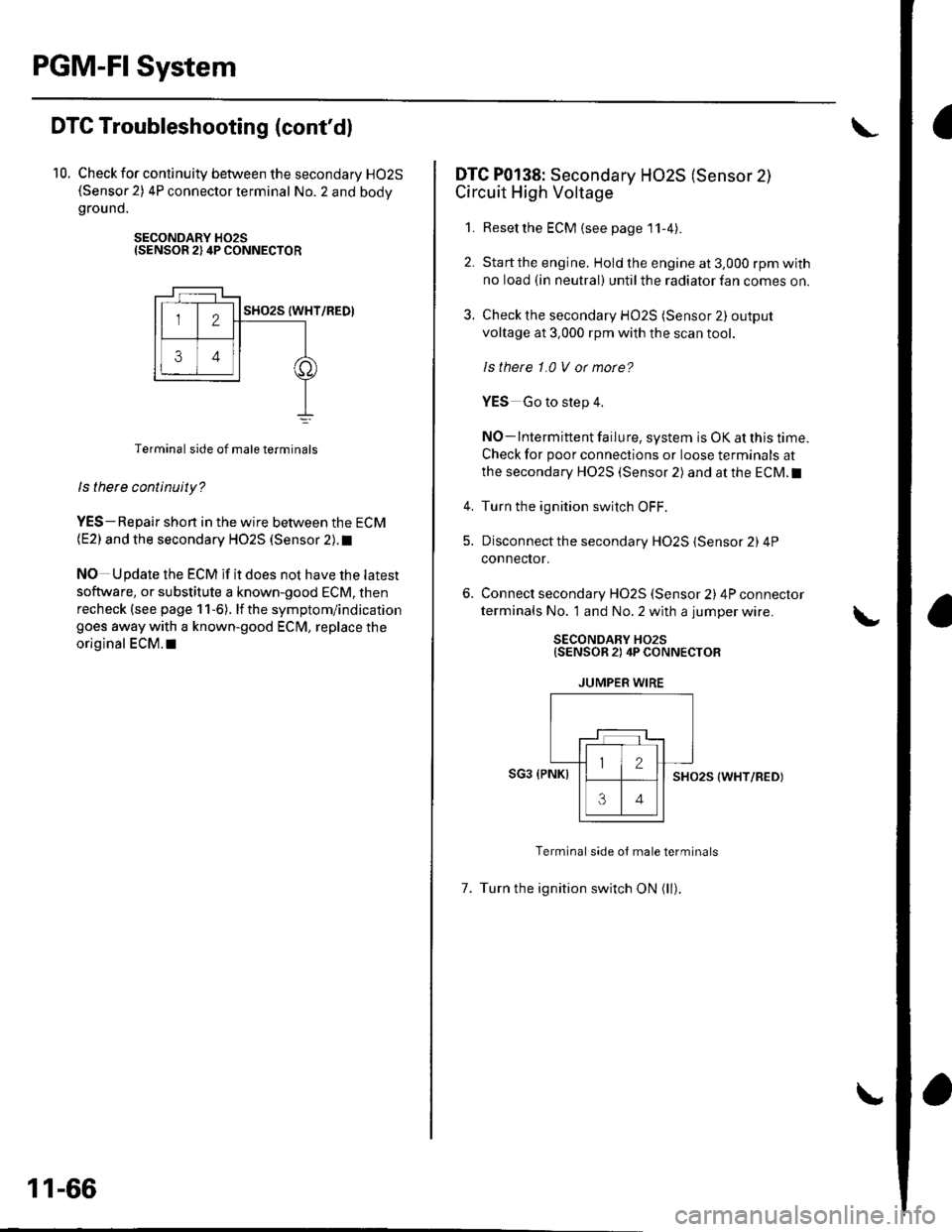
10. Check for continuity between the secondary HO2S(Sensor 2) 4P connector terminal No. 2 and bodygrou nd.
SECONDARY H02SISENSOR 2) 4P CONNECTOR
Terminal side of male terminals
ls there continuity?
YES-Repair shon in the wire between the ECM(E2) and the secondary HO2S (Sensor 2). t
NO Update the ECM if it does not have the latest
software, or substitute a known-good ECM, then
recheck (see page 1 1-6). lf the symptom/indication
goes away with a known-good ECM, replace the
original ECM.I|
11-66
DTC P0138: Secondary HO2S (Sensor 2)
Circuit High Voltage
1. Resetthe ECM {see page'11-4).
2. Startthe engine. Hold the engine at 3,000 rpm with
no load (in neutral) until the radiator fan comes on.
3. Check the secondary HO2S (Sensor 2) output
voltage at 3,000 rpm with the scan tool.
ls thete 1.0 V or morc?
YES Go to step 4.
NO-lntermittent failure, system is OK at this time.
Check for poor connections or loose terminals at
the secondary HO2S (Sensor 2) and at the ECM.I
4. Turn the ignition switch OFF.
5. Disconnect the secondary HO2S (Sensor 2) 4P
connector.
Connect secondary H02S (Sensor 2) 4P connector
terminals No. 1 and No. 2 with a jumper wire.
SECONDARY HO2S{SENSOR 2) 4P CONNECTOR
JUMPER WIRE
SG3 (PNKISHO25 (WHT/RED)
Terminal side oJ male terminals
7. Turn the ignition switch ON (ll).
Page 274 of 1139
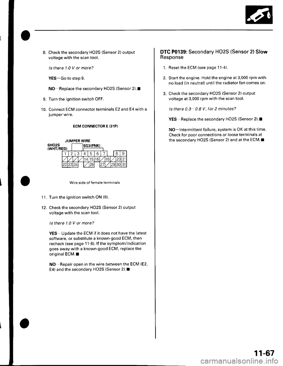
8.Check the secondary H02S (Sensor 2) output
voltage with the scan tool,
ls there 1.0 V ot mote?
YES-Go to step 9.
NO Replace the secondary HO2S (Sensor 2).1
Turn the ignition switch OFF.
Connect ECM connector terminals E2 and E4 with a
JUmper wrre.
ECM CONNECTOR E 131PI
Wire side of female terminals
Turn the ignition switch ON (ll).
Check the secondary HO2S (Sensor 2) output
voltage with the scan tool.
ls there 1.0 V or more?
YES Update the ECM if it does not have the latest
soflware, or substitute a known-good ECM, then
recheck (see page 1 1-6). lf the symptom/indication
goes away with a known-good ECM. replace the
original ECM.I
NO Repair open in the wire between the ECM (E2,
E4) and the secondary HO2S {Sensor 2).I
9.
10.
11.
12.
JUMPER WIRE
3.
DTC P0139: Secondary HO2S (Sensor 2l Slow
Response
1. Resetthe ECM (see page 11-4).
Start the engine. Hold the engine at 3,000 rpm with
no load (in neutral) until the radiator fan comes on.
Check the secondary HO2S (Sensor 2) output
voltage at 3,000 rpm with the scan tool.
ls thete 0.3- 0.8 V, fot 2 minutes?
YES Replace the secondary HO2S (Sensor 2).!
NO- lntermittent failure, system is OK at this time.
Check for poor connections or loose terminais at
the secondary HO2S (Sensor 2) and at the ECM.I
11-67
Page 284 of 1139
DTG P0325: Malfunction in Knock Sensor
Circu it
1. Reset the ECM (see page 11-4).
2. Start the engine. Hold the engine at 3,000 rpm with
no load (in neutral) until the radiator fan comes on,
then let it idle.
3. Hold the engine at 3,000-4,000 rpm for at least
60 seconds.
ls DTC P0325 indicated?
YES-Go to step 4.
NO Intermittent failure, system is OK at this time.
Check for poor connections or loose terminals at
the knock sensor and at the ECM.I
4. Turn the ignition switch OFF.
5. Disconnect the starter subharness 6P connector.
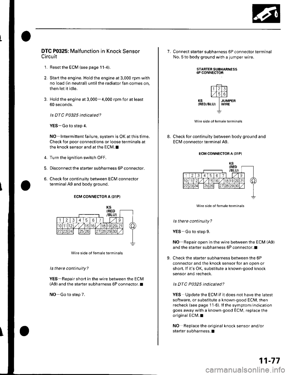
6. Check for continuity between ECM connector
terminal Ag and body ground.
ECM CONNECTOR A 131P)
Wire side of lemale terminals
ls there continuity?
YES-Repair short in the wire between the ECM(A9) and the starter subharness 6P connector.l
NO Go to step 7.
7. Connect staner subharness 6P connector terminal
No. 5 to body ground with a jumper wire.
8.
STARTER SUAHARNESS6P CONNECTOR
l1l213ll,/l5l6l._
KS IJUMPER|RED/BLU) IW|REI
Wire side of female terminals
Check for continuity between body ground and
ECM connector terminal A9.
9.
ECM CONNECTOR A {31PI
Wire side of female terminals
ls there continuity?
YES-Go to step 9.
NO Repair open in the wire between the ECM (A9)
and the starter subharness 6P connector.l
Check the starter subharness between the 6P
connector and the knock sensor for an open or
short. lf it's OK, substitute a known-good knock
sensor and recheck.
ls DTC P0325 indicated?
YES Update the ECM if it does not have the latest
software. or substitute a known-good ECM, then
recheck {see page '11-6). lf the sym ptomlindication
goes away with a known good ECM, replace the
original ECM.I
NO Replace the original knock sensor and/or
sta rte r subharness.l
11-77
Page 290 of 1139
DTG Pl106: BARO Sensor Range/Perfomance
Problem
1. Reset the ECM (see page 11-4).
2. Start the engine. Hold the engine at 3,000 rpm with
no load (in neutral) until the radiator fan comes on,
then let it idle.
Test-drive with the transmission in 4th gear.
Accelerate for 5 seconds using wide open throttle.
Check for a Temporary DTC with the scan tool.
Is Temporary DTC Pl106 indicated?
YES-Update the ECM if it does not have the latest
software, or substitute a known-good ECM. then
recheck (see page 11-6). lf the symptom/indication
goes away with a known-good ECM, replace the
original ECM. !
NO Intermittent failure, system is OK at this
time.I
DTC Pl107: BARO Sensor Circuit Low Voltage
DTC Pl108: BARO Sensor Circuit High
Voltage
1. Reset the ECM {see page 1 1-4).
2. Turn the ignition switch ON (ll).
ls DTC P1107 or P1108 indicated?
YES-Update the ECM if it does not have the iatest
software, or substitute a known-good ECI\4, then
recheck (see page 11-6). lf the symptom/indication
goes away with a known-good ECM, replace the
original ECI\4.I
NO- Intermittent failure, system is OK at this
trme.l
11-83
Page 291 of 1139
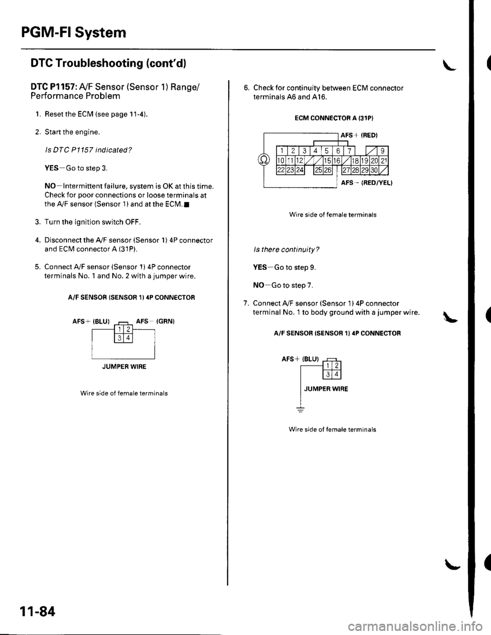
PGM-FI System
(
(
DTG Troubleshooting (cont'dl
DTC Pl157: Ay'F Sensor (Sensor 1) Range/
Performance Problem
1. Resetthe ECIM (see page 11-4).
2. Start the engine.
ls DTC Pl157 indicated?
YES-Go to step 3.
NO Intermittent failure, system is OK at this time.
Check for poor connections or loose terminals at
the Ay'F sensor (Sensor 1 ) and at the ECN4.I
Turn the ignition switch OFF.
Disconnect the Ay'F sensor (Sensor 1) 4P connector
and ECM connector A (31P).
Connect A,/F sensor (Sensor 1) 4P connector
terminals No. 1 and No. 2 with a jumper wire.
A/F SENSOR (SENSOR 1) 4P CONNECTOR
AFS+ {BLU)
Wire side of female terminals
3.
JUMPER WIRE
11-84
L
6. Check for continuity between ECM connector
terminals 46 and A16.
ECM CONNECTOR A {3IP)
Wire side of female terminals
ls there continuity?
YES Go to step 9.
NO Go to step 7.
Connect A/F sensor (Sensor 1) 4P connecror
terminal No. 1 to body ground with a jumper wire.
A/F SENSOR {SENSOR 1I 4P CONNECTOR
7.
Wire side ot female terminals