11-4 HONDA CIVIC 2002 7.G Owner's Guide
[x] Cancel search | Manufacturer: HONDA, Model Year: 2002, Model line: CIVIC, Model: HONDA CIVIC 2002 7.GPages: 1139, PDF Size: 28.19 MB
Page 329 of 1139
VTEC/VTC
10.
DTC Troubleshooting (cont'd)
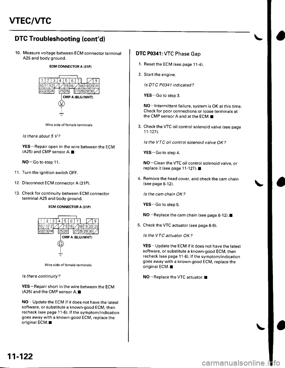
Measure voltage between ECM connector terminal
A25 and body ground.
ECM CONNECTOR A 131P)
Wire side of female te.minals
ls there about 5 V?
YES-Repair open in the wire between the ECM(A25) and CMP sensor A.I
NO-Go to step 11.
Turn the ignition switch OFF.
Disconnect ECM connector A (31P)
Check for continuity between ECM connecror
terminal A25 and body ground.
ECM CONNECTON A 131P}
Wire side of femaleterminals
ls tnere continuity?
YES-Repair short in the wire between the ECM(A25) and the CMP sensor A. t
NO Update the ECt\4 if it does not have the latest
software, or substitute a known-good ECM, thenrecheck (see page 1 1-6). lf the symptom/indicationgoes away with a known-good ECM, replace the
original ECM.I
11.
't2.
11-122
DTC P0341: WC Phase Gap
1. Resetthe ECM {see page 11-4).
2. Start the engine.
ls DTC P0341 indicated?
YES Go to step 3.
NO Intermittent failure, system is OK at this time.Check for poor connections or loose terminals atthe CMP sensor A and at the ECM.I
3. Check the VTC oil control solenoid valve (see page
11_127]-.
Isthe VTC oil control solenoid valve OK?
YES-Go to step 4.
NO-CIean the VTC oil control solenoid valve, orreplace it (see page 11-'l27l.a
4. Remove the head cover, and check the cam chain
{see page 6-12).
ls the cam chain OK?
YES Go to slep 5.
NO Replace the cam chain (see page 6-12).1
5. Check the VTC actuator (see page 6-8).
ls the VTC actuator OK?
YES- U pdate the ECM if it does not have the tatest
soflware, or substitute a known-good ECI\4, thenrecheck (see page 11-6). lf the symptom/indicationgoes away with a known-good ECM, replace the
original ECM.I
NO- Replace the VTC actuator.l
Page 330 of 1139
DTC Pl259: WEC System Malf unction
SpecialTools Required. Pressure gauge adapter 07NAJ P07010A
. A/T low pressure gauge w/panel 07406-0070300. A/T pressure hose 07406-0020201. Av/T pressure hose,2,210 mm 07IMAJ-PY4o11A
. l"/T pressure adapter 07MAJ-PY40120
. Oil pressure hose 07ZAJ-S54,4200
1. Reset the ECM (see page 11-4).
2. Check the engine oil level, and refill ifnecessary.
3. Start the engine. Hold the engine at 3,000 rpm with
no load {in neutral) until the radiator fan comes on.
4. Road testthe vehicle:
Accelerate in the 1st gear to an engine speed over
4.000 rpm. Hold the speed for at least 2 seconds. lf
DTC P1259 is not repeated during the first road test,
repeat the test two more times.
ls DTC P1259 indicated?
YES Go to step 5.
NO-lntermittent failure, system is OK at this time
Check the oil consumption if oil was added in step
2. Check for poor connections or loose terminals at
the VTEC solenoid valve, the VTEC oil pressure
switch, and at the ECI\4. I
5, Turn the ignitjon switch OFF.
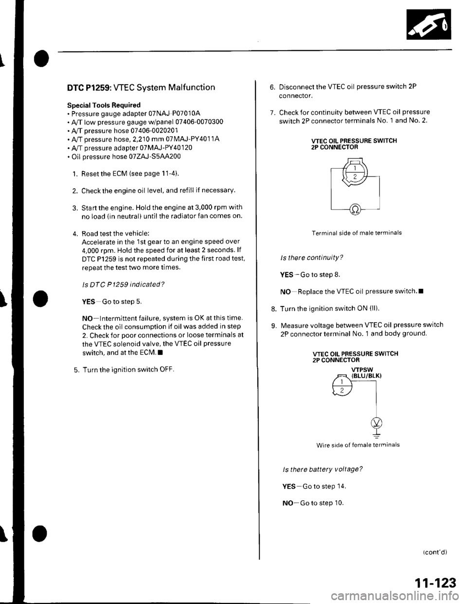
6. Disconnect the VTEC oil pressureswitch 2P
connector.
7. Check for continuity between VTEC oil pressure
switch 2P connector terminals No. 1 and No. 2
VTEC OIL PRESSURE SWITCH2P CONNECTOR
Terminal side of male terminals
Is there continuity?
YES-Go to step 8.
NO Replace the VTEC oil pressure switch.l
8. Turn the ignition switch ON (ll).
9. Measure voltage between VTEC oil pressure switch
2P connector terminal No. 1 and body ground
ls there battety voltage?
YES Go to steP 14.
NO-Go to step 10.
(cont'd)
VTEC OIL PRESSURE SWITCH2P CONNECTOR
VTPSW
/T {BLU/BLK}
{.--r r-l'--.l
J II
oI
Wire side of female terminals
11-123
Page 338 of 1139
DTC Pl519: IAC Valve Circuit Malf unction
1. Resetthe ECM (see page 11-4).
2. Turn the ignition switch ON (ll)
ls DTC P 1519 indicated?
YES Go to step 3.
NO-lntermittent failure, system is OK at this time.
Check for poor connections or loose terminals at
the IAC valve and at the ECM.I
3. Turn the ignition switch OFF.
4. Disconnect the IAC valve 3P connector.
5. Turn the ignition switch ON (ll).
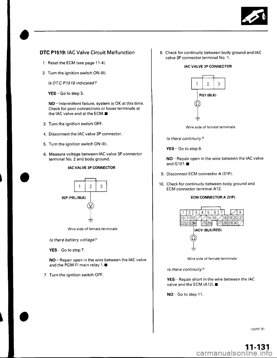
6. Measure voltage betlveen IAC valve 3P connector
terminal No. 2 and body ground.
IAC VALVE 3P CONNECTOR
IGP {YEL/BLK)
Wire side of female terminals
ls there battery voltage?
YES Go to step 7.
NO-Repair open in the wire between the IAC valve
and the PGM-Fl main relay 1.1
Turn the ignition switch OFF.
123
7.
8, Check for continuity between body ground and IAC
valve 3P connector terminal No. 1.
IAC VALVE 3P CONNECTOR
123
PG1 {BLK}
a.
Wire side of lemale terminals
Is there continuity?
YES-Go to step 9.
NO Repair open in the wire between the IAC valve
and G'101.1
Disconnect ECM connector A (31P)
Check for continuity between body ground and
ECM connector terminal A12.
ECM CONNECTOR A 131P)
r l2l3l4 5617s
r01l12 .// 1156 ./118192C21
da25126l27ln2930
IACV {BLK/RED}
1,)
Wire side oJ Jemale terminals
ls there continuity?
YES-Repair short in the wire between the IAC
valve and the ECM (A12).1
NO Go to step 1 1.
9.
10.
LCOnI Ol
11-131
Page 375 of 1139
PCV System
DTC Troubleshooting
DTC P1505: PCV Air Leakage
1. Reset the ECM (see page 11-4).
2. Start the engine. Hold the engine at 3,000 rpm with
no load (in neutral) until the radiator fan comes on
3. Let the engine idle tor al least 40 seconds with the
throttle fully closed.
4. Check for a DTC P1505 with the scan tool
ls DTC P1505 indicated?
YES-Check these parts for vacuum leaks l
. PCV valve. PCV hose. EVAP canister purge valve
. Throttle body. Brake booster hose
NO - Intermittent failure, system is OK at this
time.l
11-168
Page 379 of 1139
EVAP System
DTC Troubleshooting (cont'd)
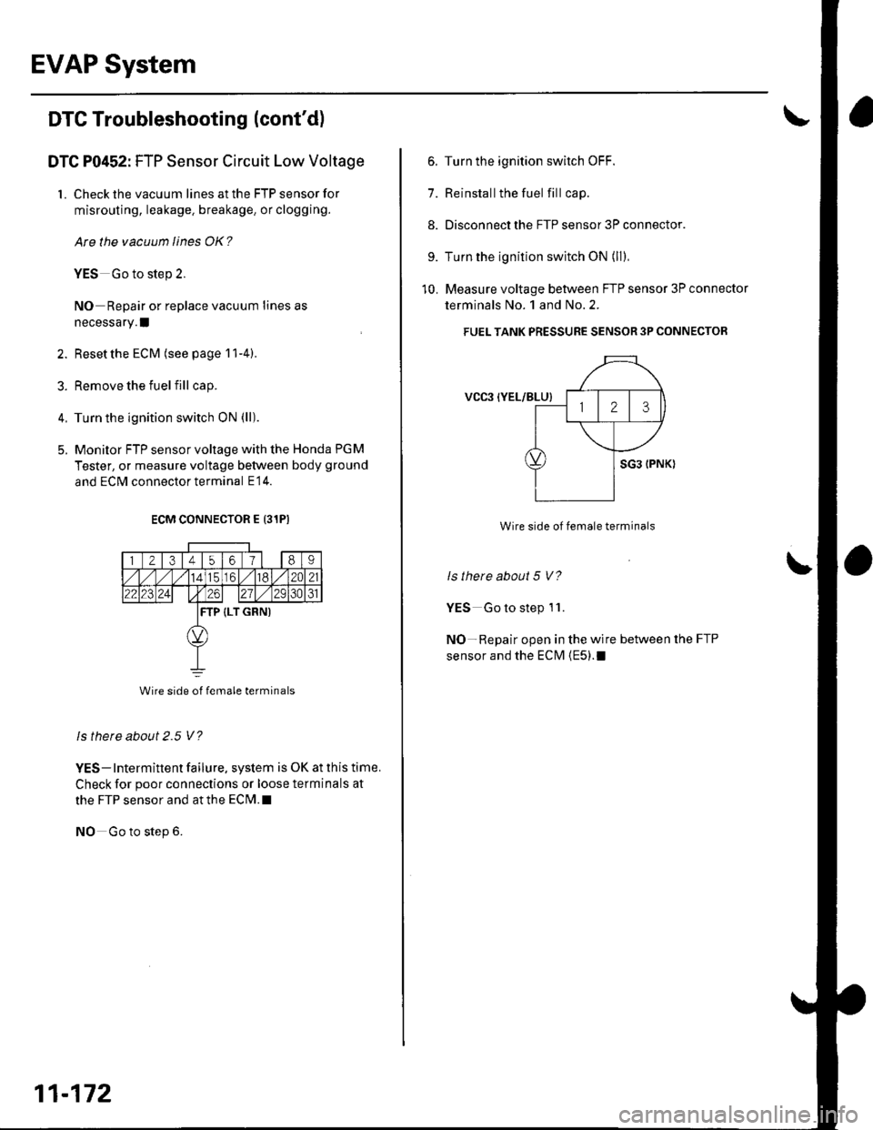
DTC P0452: FTP Sensor Circuit Low Voltage
1. Check the vacuum lines at the FTP sensor for
misrouting, leakage. breakage, or clogging.
Are the vacuum lines OK?
YES Go to step 2.
NO Repair or replace vacuum lines as
necessary. I
2. Reset the ECM (see page 11-4).
3. Remove the fuelfill cap.
4. Turn the ignition switch ON (ll)
5. Monitor FTP sensor voltage with the Honda PGM
Tester, or measure voltage between body ground
and ECM connector terminal E14.
ECM CONNECTOR E 131PI
1 2t3t45o/89
././114tc61./182C21
22123241 t26271/ 2931
TP (LT GRN)
Wire side of female terminals
ls thete about 2.5 V?
YES- Intermittent failure, system is OK at this time.
Check for poor connections or loose terminals at
the FTP sensor and at the ECrM.l
NO Go to step 6.
11-172
6. Turn the ignition switch OFF.
7. Reinstallthe fuel fill cap.
8. Disconnect the FTP sensor 3P connector.
9. Turn the ignition switch ON (ll)
10. Measure voltage between FTP sensor 3P connector
terminals No. 1 and No.2.
FUEL TANK PRESSURE SENSOR 3P CONNECTOR
VCgl {YEL/BLU}
Wire side of female terminals
ls there about 5 V?
YES Go to step 1 '1.
NO-Repair open in the wire between the FTP
sensor and the ECM {E5).1
Page 806 of 1139
Mode Control Motor Test
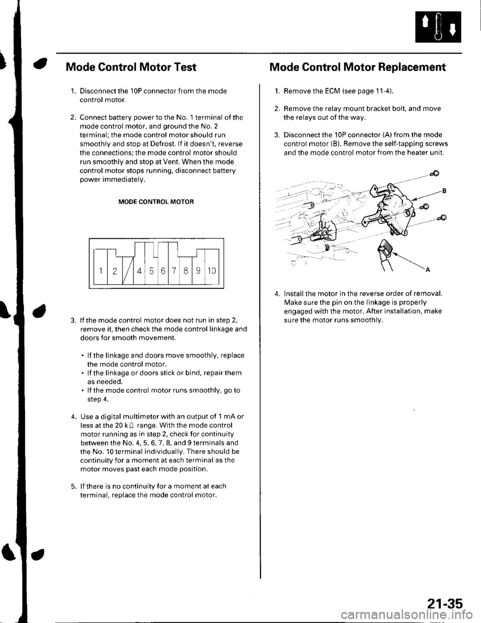
Disconnect the 10P connector from the mode
control motor.
Connect battery power to the No. 1 terminal of the
mode control motor, and ground the No. 2
terminal; the mode control motor should run
smoothly and stop at Defrost. lf it doesn't, reverse
the connections; the mode control motor should
run smoothly and stop at Vent. When the mode
control motor stops running, disconnect battery
power immediately.
'1.
4.
MODE CONTROL MOTOR
3. lfthe mode control motor does not run in step 2,
remove it, then check the mode control linkage and
doors for smooth movement.
. lf the linkage and doors move smoothly. replace
the mode control motor.. lf the linkage ordoorsstick or bind, repairthem
as neeoeo.. lfthe mode control motor runs smoothly, go to
step 4.
Use a digital multimeter with an output of 1 mA or
less at the 20 k Q range. With the mode control
motor running as in step 2, check for continuity
between the No. 4,5,6,7,8, and 9 terminals and
the No. 10 terminal individually. There should be
continuity for a moment at each terminal as the
motor moves past each mode position.
lf there is no continuity for a moment at each
terminal. replace the mode control motor.
Mode Control Motor Replacement
2.
3.
1.Remove the ECM (see page 11-4).
Remove the relay mount bracket bolt, and move
the relays out of the way.
Disconnect the 10P connector {A) from the mode
control motor (B). Remove the self-tapping screws
and the mode control motor from the heater unit.
lnstallthe motor in the reverse order of removal.
lvlake sure the pin on the linkage is properly
engaged with the motor. After installation. make
sure the motor runs smoothly.
4.
21-35
Page 807 of 1139
Heating and Air Conditioning
Recirculation Control Motor Test
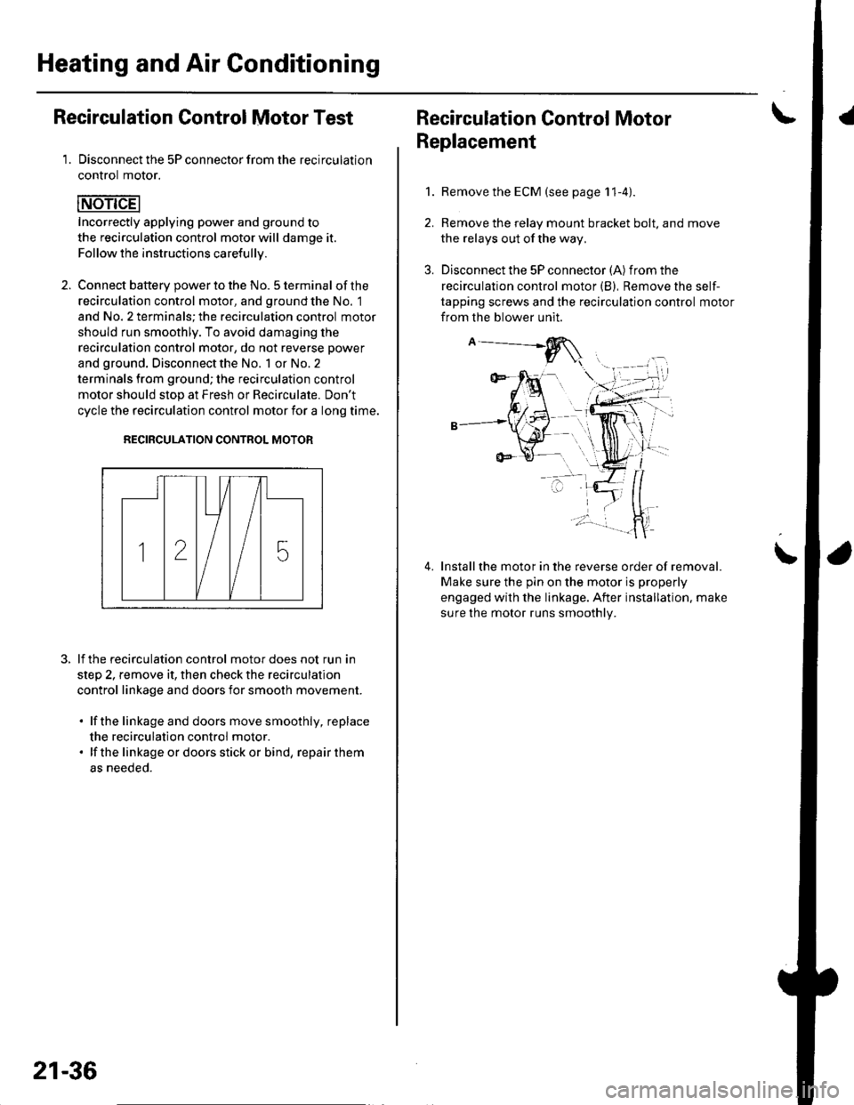
1. Disconnect the 5P connector from the recirculation
control motor.
Incorrectly applying power and ground to
the recirculation control motor will damge it.
Follow the instructions carefullv.
2. Connect batterv oower to the No. 5 terminal ofthe
recirculation control motor, and ground the No. 1
and No. 2 terminals; the recirculation control motor
should run smoothly. To avoid damaging the
recirculation control motor, do not reverse power
and ground. Disconnect the No. 1 or No. 2
terminals from ground; the recirculation control
motor should stop at Fresh or Recirculate. Don't
cycle the recirculation control motor {or a long time.
RECIRCULATION CONTROL MOTOR
lf the recirculation control motor does not run in
step 2, remove it, then check the recirculation
control linkage and doors for smooth movement.
. lfthe linkage and doors move smoothly, replace
the recirculation control motor.. lf the linkageordoorsstickor bind, repairthem
as neeoeo.
21-36
Recirculation Control MotorI
Replacement
1.Remove the ECM (see page 11-4).
Remove the relay mount bracket bolt. and move
the relays out of the way,
Disconnect the 5P connector (A) from the
recirculation control motor (B), Remove the self-
tapping screws and the recirculation control motor
from the blower unit.
Installthe motor in the reverse order of removal.
Make sure the pin on the motor is properly
engaged with the linkage. After installation. make
sure the motor runs smoothly.
\
Page 811 of 1139
Heating and Air Gonditioning
Blower Unit Removal and Installation {cont'd}
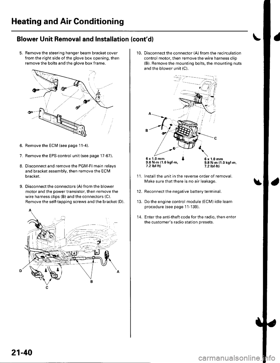
Remove the steering hanger beam bracket cover
from the right side of the glove box opening, then
remove the bolts and the olove box frame.
1.
8.
9.
Remove the ECM (see page 11-4).
Remove the EPS control unit (see page 17-67).
Disconnect and remove the PGM-Fl main relays
and bracket assembly, then remove the ECM
bracket.
Disconnect the connectors {A) from the blower
motor and the power transistor, then remove the
wire harness clips (B) and the connectors (C).
Remove the self-tapping screws and the bracket (D).
A
21-40
10. Disconnectthe connector {A) from the recirculation
control motor, then remove the wire harness clip
{B). Remove the mounting bolts, the mounting nuts
and the blower unit (C).
6x 1.0 mm I9.8 N.m (1.0 kgt.m,7.2 tbt.ftl
6x1.0mm9.8 N.m (1.0 kgf.m,?.2 tbf.ft)
11.
14.
Installlhe unit in the reverse order of removal.
Make sure that there is no air leakage.
Reconnect the negative battery terminal.
Do the engine control module (ECM) idle learn
procedure {see page 11-139).
Enter the anti-theft code for the radio, then enter
the customer's radio station presets.
\
'13.
Page 993 of 1139
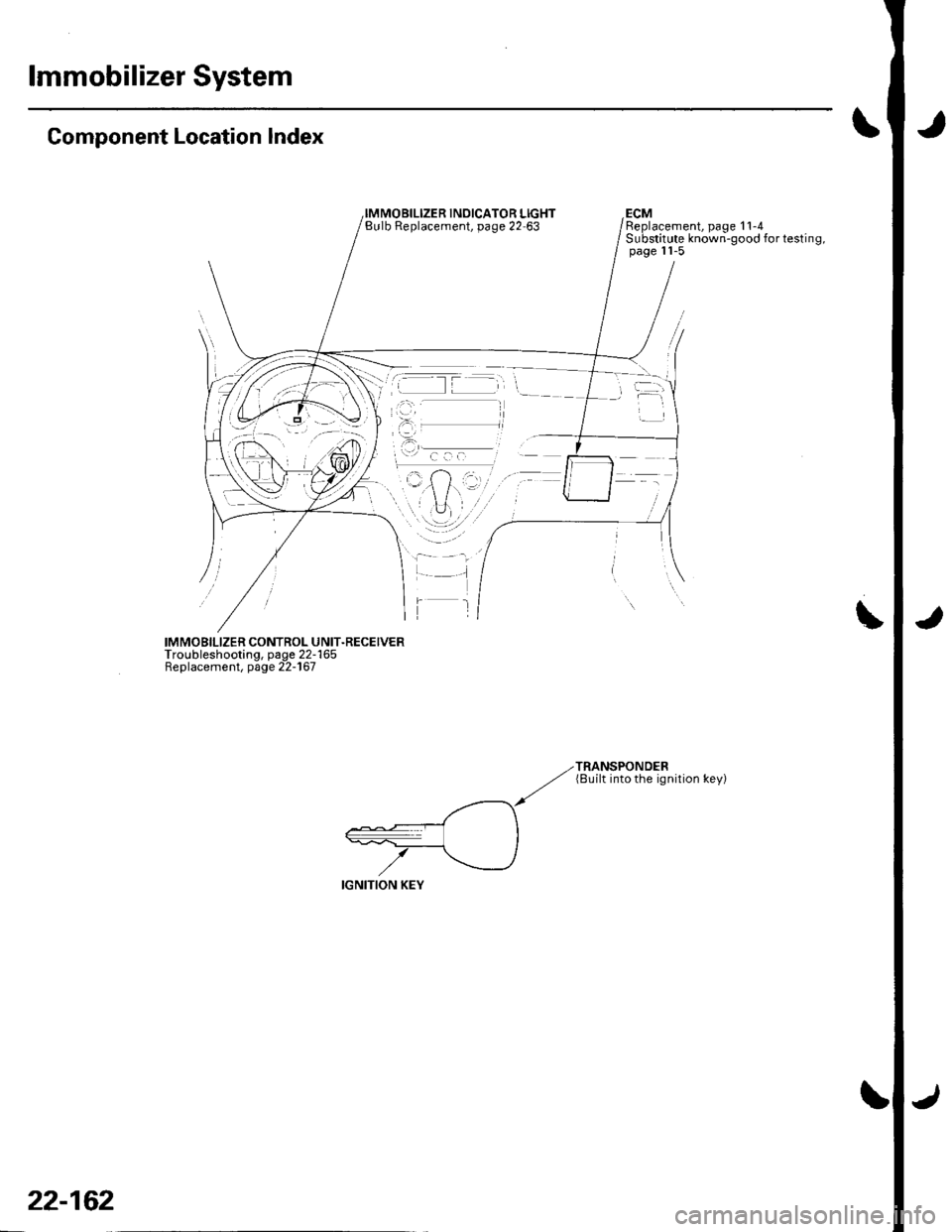
lmmobilizer System
Component Location Index
INOICATOR LIGHTBulb Replacement, page 22 63ECMReplacement, page 11-4Substitute known-good for testing,page 11-5
IMMOBILIZER CONTROL UNIT.RECEIVERTroubleshooting, page 22-165Replacement, page 22-167
TRANSPONDER(8uilt into the ignition key)
22-162
Page 1036 of 1139
IJ
lr
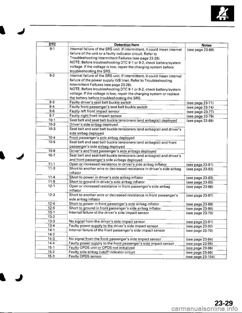
DTCDetection ltemNotes9-1Internal failure of the SRS unit. lf intermittent, it could mean internalfailure of the unit or a faulty indicator circuit. Refer toTroubleshooting Intermittent Failures (see page 23-26).
NOTE: Before troubleshooting DTC 9-1 or 9-2, check battery/systemvoltage. lf the voltage is low, repair the charging system beforetroubleshooting the SRS.
(see page 23-69)
9-2Internal failure of the SRS unit. lf intermittent, it could mean internalfailu re of the power supply (VB line). Refer to TroubleshootingIntermittent Failures (see page 23-26).
NOTE: Before troubleshooting DTC 9-1 or 9-2, check battery/systemvoltage. lf the voltage is low, repair the charging system or replacethe b€ttery before troubleshooting the SRS.
9-3Faulty driver's seat belt buckle switch(see Daqe 23-71)9-4
9-6
FaultLtglt passenger's seat belt buckle switch
Faulty Ieft front imDact sensorlgqgfage 23-74)
{see Daqe 23-77)9-7Faulty right front impact sensor(see paqe 23-79)10-1Seat belt and seat belt buckle tensioners (and airbag(s)) deployedDriver's side airbag deployed
Seat belt and seat belt buckle tensioners (and airbag(s)) and driver'sside airbag deployed
Front passenqer's side airbao deDloved
(see page 23-69)10-2
r0-3
'10-4
'10-5Seat belt and seat belt buckle tensioners (and airbag(s)) and frontpassenqer's side airbaq deDloved
10-6Driver's and front passenqer's side al10-7Seat belt and seat belt buckle tensioners (and airbag(s)) and driver'sand front passenger's side airbags deployed
1 1-1Open or increased resistance in driver's side airbao inflator(see paqe 23-81)Short to another wire or decreased resistance in driver's side airbaoinflator
(see page 23-82)
11-4Short to power in driver's side airbaq inflator(see oaqe 23-83)I t-5Short to ground in driver's side airbaq inflator{see paqe 23-85)Open or increased resistance in front passenger's side airbaginflator
(see page 23-86)
Short to another wire or decreased resistance in front passenger's
side airbag inflator
(see page 23-87)
12-4Short to power in front passenqer's side airbaq inflator{see Daqe zJ-uu}I z-5Short to ground in front passenger's side airbaq inflator(see oaqe 23-90)13-1Internal failure of the driver's side impact sensor(see page 23-70)
No signal from the driver's side impact sensor(see paqe 23-91)13-4
14-1-7ii,
Faulty power supply to the df,rglllug t Opact s9I99LInternal failure ofthe front passenger's side impact sensor
(see page 23-92)(see page 23-70)
14-3No signal from the front passenger's side impact sensor(see paqe 23-94)14-4Faulty power supply to the front passenqer's side impact sensor(see page 23-95)15-1Faultv OPDS unit or OPDS not initialized(see paqe 23-96115-2Faulty side airbag cutoff indicator circuit(see Daqe 23-99)15-3Faulty OPDS sensor(see oaoe 23-104)
IJ
23-29