drain bolt HONDA CIVIC 2002 7.G User Guide
[x] Cancel search | Manufacturer: HONDA, Model Year: 2002, Model line: CIVIC, Model: HONDA CIVIC 2002 7.GPages: 1139, PDF Size: 28.19 MB
Page 426 of 1139
Manual Transmission
Transmission Disassembly (cont'd)
NOTE: Place the clutch housing on two pieces of wood
thick enough to keep the mainshaft from hitting the
workbench.
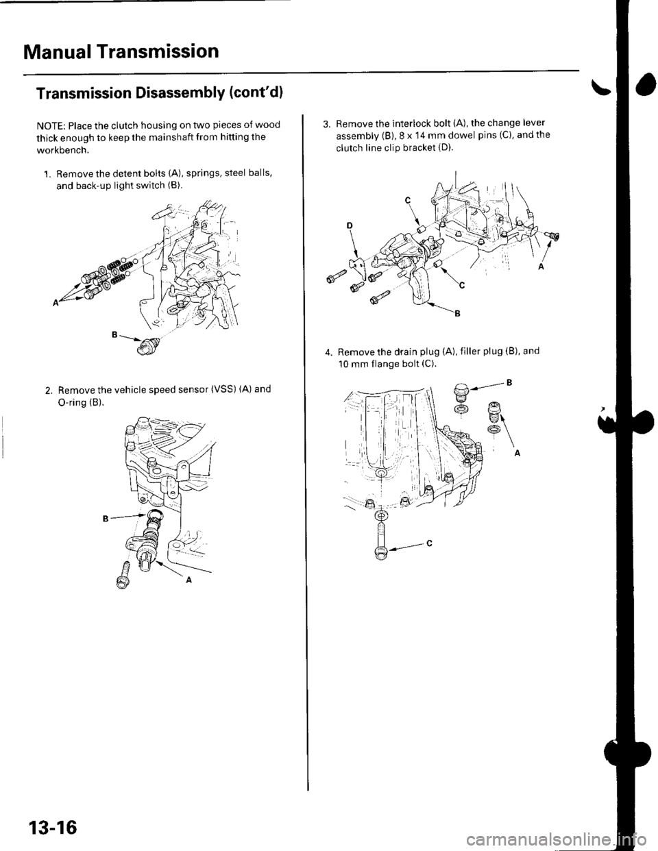
1. Remove the detent bolts (A), springs, steel balls,
and back-up light switch (B).
Remove the vehicle speed sensor (VSS) (A) and
O-ring (B).
13-16
3, Remove the interlock bolt (A), the change lever
assembly (B), 8 x 14 mm dowel pins (C), andthe
clutch line clip bracket {D).
€
Remove the drain plug (A), filler plug (B), and
10 mm flange bolt (C).
Page 459 of 1139
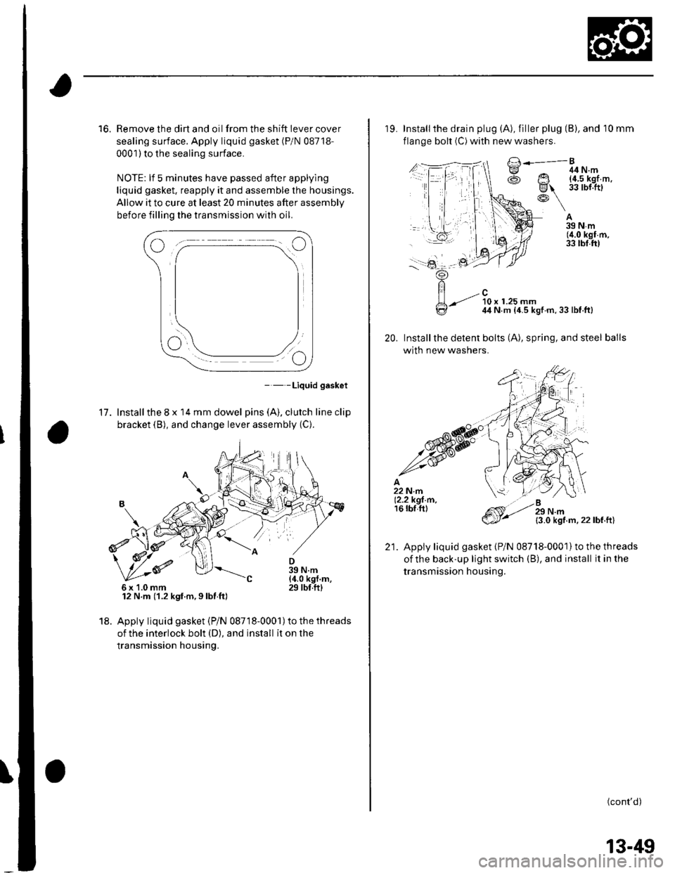
16. Remove the dirt and oil from the shift iever cover
sealing surface. Apply liquid gasket (P/N 08718-
0001) to the sealing surface.
NOTE: lf 5 minutes have passed after applylng
liquid gasket. reapply it and assemble the housings.
Allow it to cure at least 20 minutes after assembly
before filling the transmission with oil.
- - -Liquid gasket
17. Installthe 8 x 14 mm dowel pins (A). clutch line clip
bracket (B), and change lever assembly (C).
12 N.m (1.2 kgf.m,9lbt ft)
18. Apply liquid gasket (Pi N 08718-0001) to the threads
of the interlock bolt (D), and install it on the
transmission housing.
6x1.0mm
19. Installthe drain plug (A), filler plug (B), and 10 mm
flange bolt (C) with new washers.
A39Nm(4.0 kgf m,33 tbl.ft)
20.
/..l-.=,'-Bg ^ 44N.m
@ Ut !?iJl'.'l,''
R\-: \
-.-t ?0, ,.ru ^44 N m {4.5 kgt m,33lbf.ft}
Installthe detent bolts (A), spring, and steel balls
with new washers.
{3.0 kgf.m.22lbf.ft)
Apply liquid gasket {P/N 08718-0001}to the threads
oithe back-up light switch (B), and install it in the
transmission housing.
(cont'd)
21.
13-49
Page 618 of 1139
Rear Brake Caliper Overhaul
Frequent inhalation of brake pad dust, regardless of material composition, could be hazardous to your health.
' Avoid breathing dust particles.
. Never use an air hose or brush to clean brake assemblies. Use an OSHA-approved vacuum cleaner'
Remove, disassemble, inspect, reassemble, and installthe caliper, and note these items:
. Donotspill brake fluid on the vehicle; it may damage the paint; if brake f luid gets on the paint, wash it off
immediately with water.. To prevent dripping. cover disconnected hose joints with rags or shop towels.
. Cleanall partsinbrakefluidandairdry;blowoutall passageswith compressed air'
. Before reassembling, check that all parts are free of dust and other foreign particles
. Replace pans with new ones as specified in the illustration.. Make sure no dirt or other foreign matter contaminates the brake fluid.
. When reusing pads, always reinstallthem in their original positions to prevent loss of b ra king efficie ncy.
. Do not reuse drained brake fluid.
. Use only clean Honda DOT 3 brake fluid. Non-Honda brake fluid can cause corrosion and shorten the life of the
system.. Do not mix different brands ot brake fluid as they may not be compatible.
. Coatthe piston, piston seal groove, and caliper bore with clean brake fluid.
. Make sure no grease or oil gets on the brake discs or pads.
. Replaceall rubber parts with new ones whenever disassembled.
. After installing the caliper, check the brake hose and line for leaks, interference. and twisting.
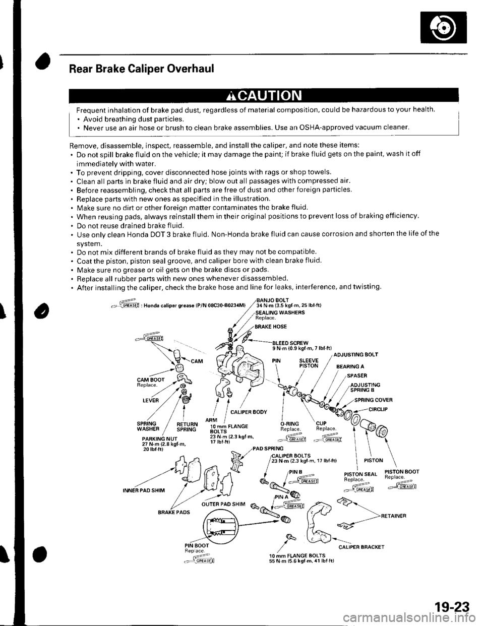
oG , nonau."rip6r qreas€ lP/N 08c30-aoa4Ml34 N.m (3.5 kgf m,25lbtft)BOLT
WASHERS
BRAKE HOSE
a
l,i,,'IltE" / !!;,ff
olT-J,.o"c.O.RING CUPBeplace. Beplace.
.ARKING NUr lii.'i rz.r rgr.. Gd ffi27Nm{2.8kgtm,
\-"o, V((rA ",1 ;[.,.JF /;;;;---
t H\a \l / t,i*t'*"
?,,.t/*"^.,,.:,"", /"V4#
ADJUSTING BOLT
,/
27Nm{2.8kgf.m,20 tbf.ftr PAD SPRING
A,n Na 7lfl,lif,loffi ',,0,n, ,,:,o" \
--t)(*ff l^7k ''"'t!1'ry#'
INNEBPA'SHIM
/ .r.:._U i*E'( ":;*" *dF ,.2>a>-
fr.x{_>@ fftt **-->**^'"
,,.-"iV ,/q &'"o.,"."""o"^.,
: 10 MM FLANGE BOLTS.:r=,9!q!q}l 55 N m (5.6 lgf-m, 4r lbt ft)
19-23
Page 696 of 1139
Moonroof
1.
Frame and Drain Tube Replacement
Remove these items:
. Headliner (see page 20-54). Moonroof glass (see page 20-37)
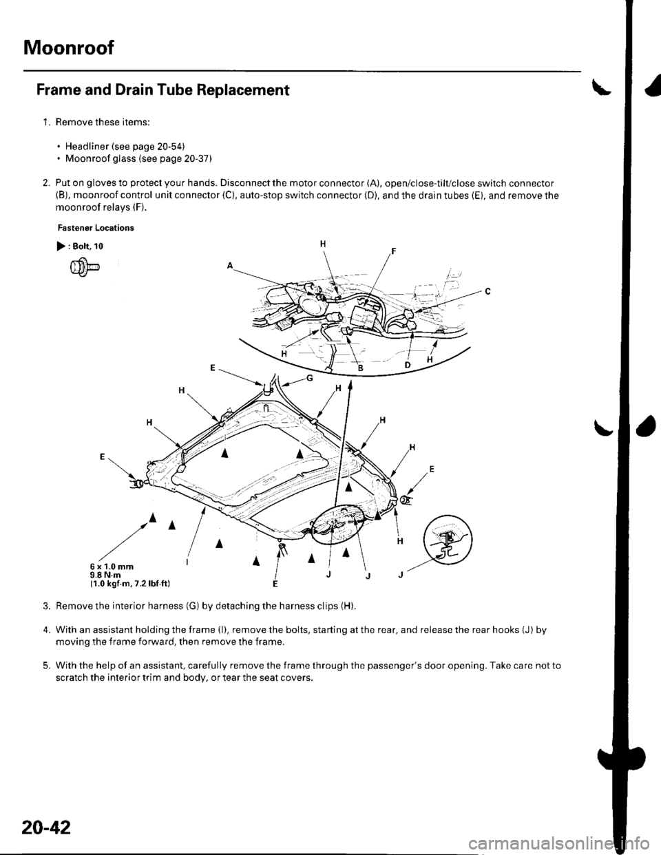
Put on gloves to protect you r hands. Disconnect the motor connector (A), open/close-tilt/close switch connector
{B), moonroof control unit connector {C), auto-stop switch connector (D), and the drain tubes (Ei, and remove the
moonroof relays (F).
Fastenor Locations
> : Bolt, 10
{um
/^
6x1.0mm9.8 N.m(1.0 kgf.m,7.2lbf ft)
4.
5.
2.
irl
@
Remove the interior harness (G) by detaching the harness clips (H).
With an assistant holding the frame (l). remove the bolts, starting at the rear, and release the rear hooks (J) by
moving the f rame forward, then remove the frame.
With the help of an assistant, carefully remove the frame through the passenger's door opening. Take care not to
scratch the interior trim and body, or tear the seat covers.
20-42
Page 698 of 1139
Moonroof
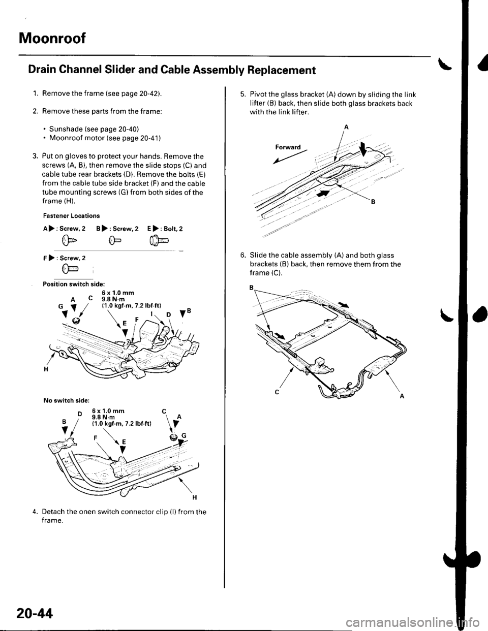
Drain Channel Slider and Cable Assembly Replacement
1. Remove the frame (see page 20-42).
2. Remove these parts from the frame:
. Sunshade (see page 20-40). Moonroof motor (see page 20-41)
3. Put on gloves to protect your hands, Remove the
screws (A, B), then remove the slide stops (C) and
cable tube rear brackets (D). Remove the bolts (E)
from the cable tube side bracket (F) and the cable
tube mounting screws (G) from both sides of the
frame (H).
Fastener Locations
A> r Screw.2 B): Screw,2
@@
r):
Position switch side:
6x1.0mmA c g,a N.m
No switch sidel
o
E>:Bolt,2
Screw
6\-'1
6x1.0mm C9.8 N.m11.0 kgf.m, 7.2 lbf.ft)
Detach the onen switch connector clip {l)from the
frame.
B
V
20-44
5. Pivotthe glass bracket (A) down by sliding the link
lifter (B) back, then slide both glass brackets back
with the link lifter.
Slide the cable assembly (A) and both glass
brackets (B) back, then remove them from the
frame (C).
Page 814 of 1139
Heater Unit/Core Replacement
SRS components are located in this area. Review the
SRS component locations (see page 23'13), and
precautions and procedures (see page 23-14) in the SRS
section before performing repairs or service.
1. Make sure you have the anti-theft code forthe radio,
then write down the freouencies for the radio's
Dreset buttons.
4.
Disconnect the negative cable from the battery,
Disconnect the suction and receiver lines from the
evaporator core (see page 21-42).
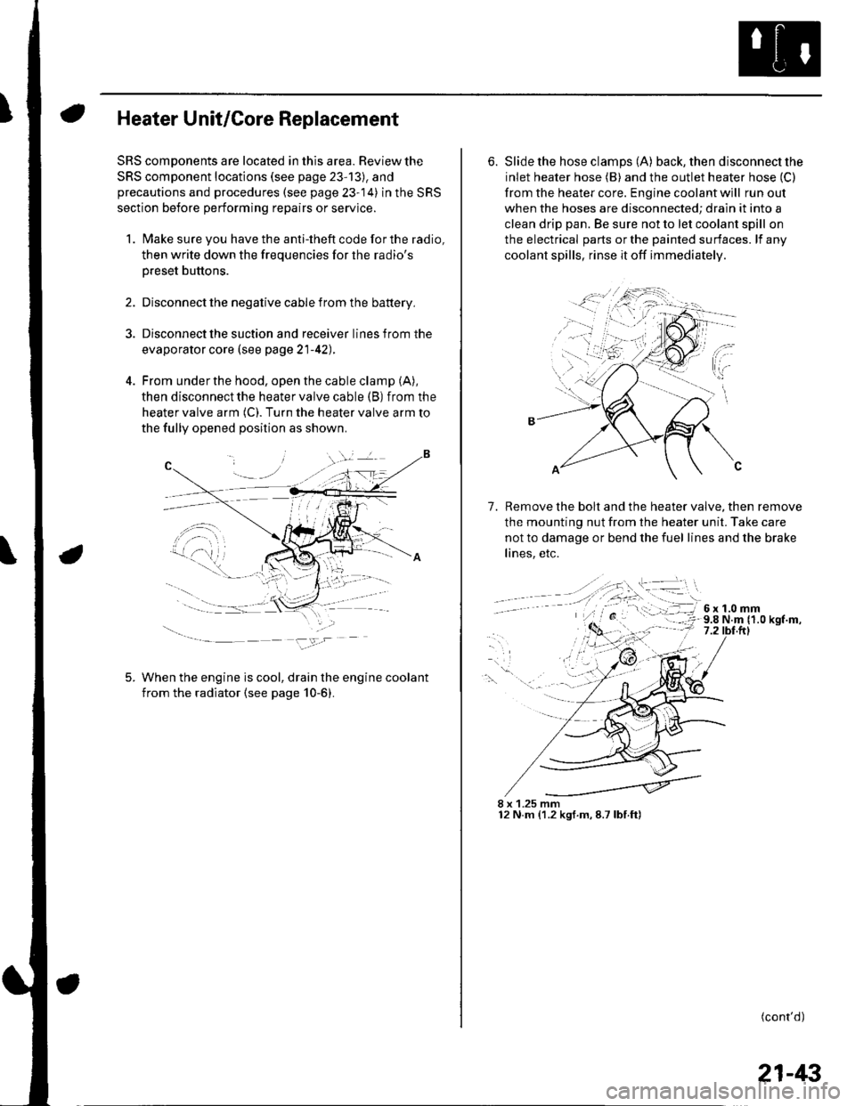
From under the hood, open the cable clamp (A),
then disconnect the heater valve cable (B) from the
heater valve arm (C). Turn the heater valve arm to
the fully opened position as shown
When the engine is cool, drain the engine coolant
from the radiator (see page 10-6).
6. Slide the hose clamps (A) back, the n d isconnect the
inlet heater hose (B) and the outlet heater hose (C)
from the heater core. Engine coolant will run out
when the hoses are disconnected; drain it into a
clean drip pan. Be sure not to let coolant spill on
the electrical parts or the painted surfaces. lf any
coolant spills, rinse it off immediately.
Remove the bolt and the heater valve, then remove
the mounting nut from the heater unit. Take care
not to damage or bend the fuel lines and the brake
lines, etc.
7.
8 x 1.25 mm12 N.m (1.2 kgf.m,8.7lbf.ft)
(cont'd)
21-43