diagram HONDA CIVIC 2002 7.G Workshop Manual
[x] Cancel search | Manufacturer: HONDA, Model Year: 2002, Model line: CIVIC, Model: HONDA CIVIC 2002 7.GPages: 1139, PDF Size: 28.19 MB
Page 36 of 1139
\.
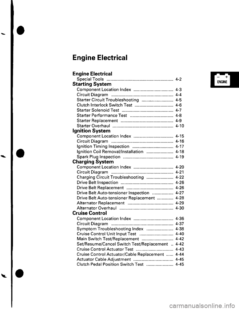
Engine Electrical
Engine Electrical
SpecialTools
Starting System
Comoonent Location Index ...............
Circuit Diagram
Starter Circu it Troubleshooting
Clutch Interlock Switch Test
Starter Solenoid Test ..............
Sta rter Performance Test
Starter Reolacement ...............
Starter Overhaul .......................
lgnition System
Component Location Index ...............
Circuit Diagram
lgnition Timing Inspection
lgnition Coil Removal/1nsta11ation .......................
Spark Plug Inspection
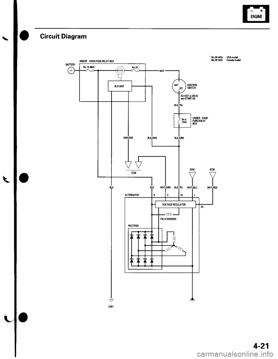
Charging System
Component Location Index .................................. 4-2O
Circuit Diagram ........................... 4-21
Charging Circuit Troubleshooting ....................... 4-22
Drive Belt Inspection ................... 4-26
Drive Beft Replacement .............. 4-26
Drive BeftAuto-tensioner Inspection .................. 4-27
Drive Beft Auto-tensioner Replacement .............. 4-28
Alternator Reolacement ............. 4-29
Alternator Overhaul ................ .... 4-30
Cruise Control
Component Location Index .................................. 4-36
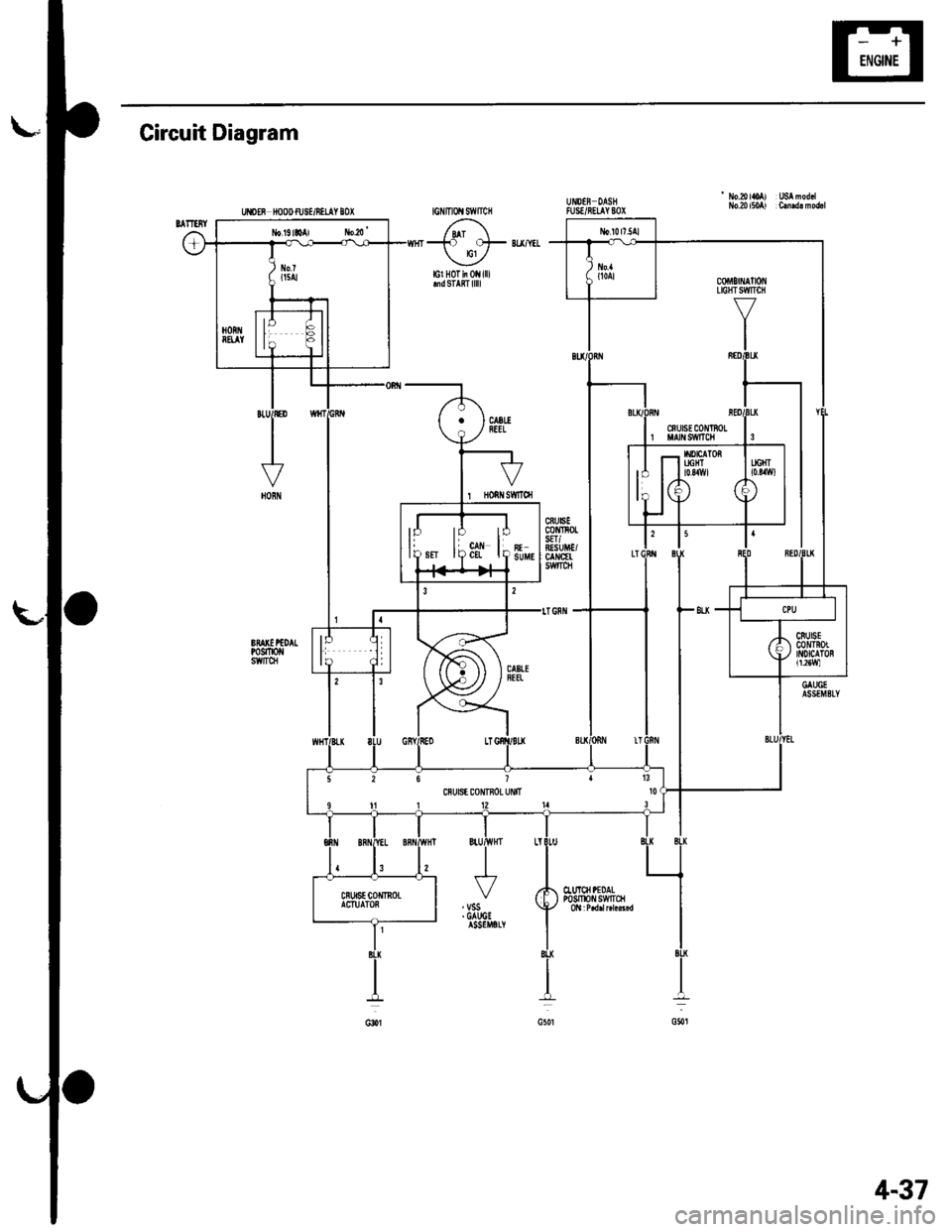
Circuit Diagram ........................... 4-37
Symptom Troubleshooting Index ....................... 4-38
Cruise Control Unit lnDut Test ............................. 4-40
Main Switch TesVReolacement ........................... 4-42
SeVResume/Cancel Switch TesVReplacement .. 4-42
Cruise Control Actuator Test ...... 4-43
Cruise Control Actuator/Cable Replacement ...... 4-44
Actuator Cable Adjustment .................................. 4-45
Clutch Pedal Position Switch Test ....................... 4-45
4-2
4-J
4-4
4-5
4-6
4-7
4-8
4-9
4-10
4-15
4-16
4-17
4-18
4- 19
-+
ENGINE
Page 39 of 1139
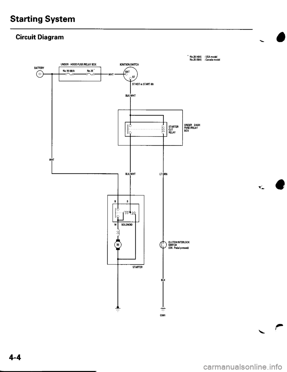
Starting System
Circuit Diagram
- ilo.20lOA) :USA motklNo.2! l50A) : C.nid. model
UiIOEN H@D fUSE/REI.IY BOX
UNDEi OASTIFUST/ifLAY80x
Y.
ST HOT in STA8T illl
cLuTot [{Tr8LocKswtlcH
4-4
a
Page 43 of 1139
Starting System
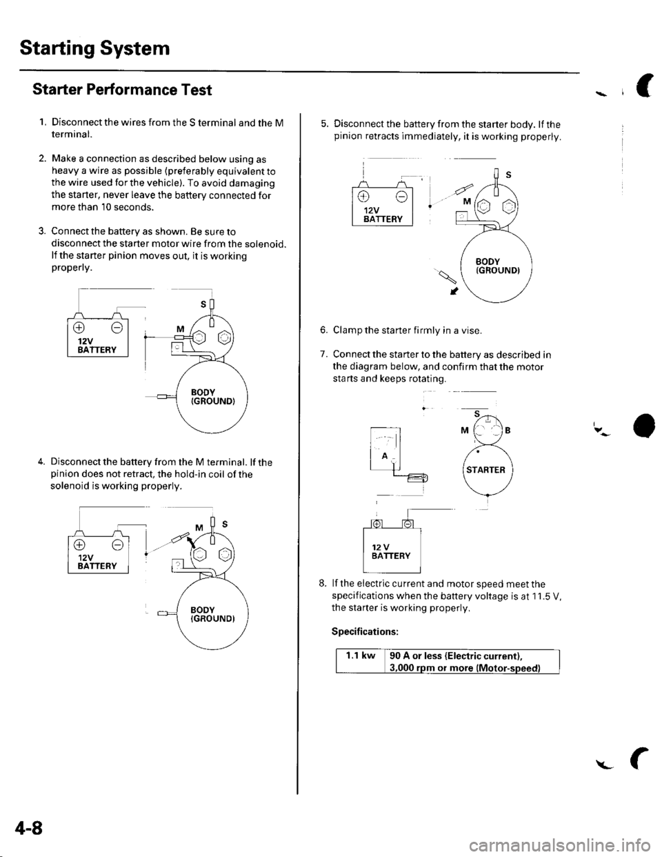
Starter Performance Test
1,Disconnect the wires from the S terminal and the M
termrnal.
Make a connection as described below using as
heavy a wire as possible (preterably equivalent to
the wire used for the vehicle). To avoid damaging
the starter, never leave the battery connected for
more than 10 seconds,
Connect the battery as shown. Be sure to
disconnect the starter motor wire from the solenoid.
lf the starter pinion moves out, it is workingpropefly.
Disconnect the battery from the M terminal. lf thepinion does not retract, the hold-in coil of the
solenoid is working properly.
4-8
L
5. Disconnect the battery from the starter body. lfthepinion retracts immediately, it is working properly.
Clamp the starter firmly in a vise.
Connect the starter to the battery as described in
the diagram below, and confirm that the motor
sta rts and keeps rotating.
6.
7.
lf the eiectric cu rrent and motor speed meet the
specifications when the battery voltage is at 1 1.5 V,
the staner is working properly,
Specifications:
1.1 kw 90 A or less (Electric current),
ot more
Page 51 of 1139
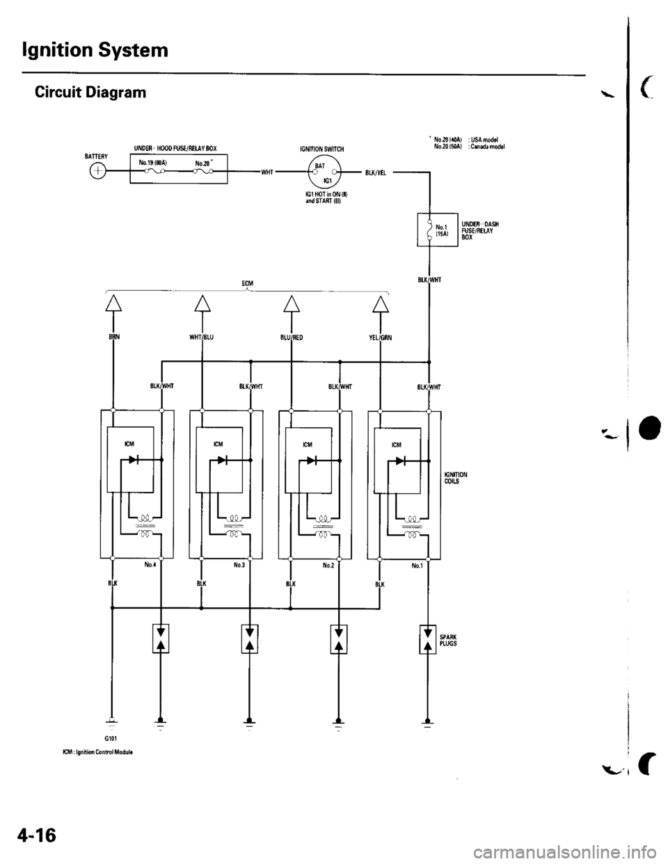
lgnition System
Gircuit Diagram
'No.20lOA) :USAmo&lNo.A l50A) :Cmrda model
(
UNDEB HOOD FUST/8TIAY M)(
lG1 tioT in 0N {ll)rd SIARI illl)
4-16
Page 56 of 1139
\
L
Circuit Diagram
'flo. {l0Al :uSA hod.lilo.20l50Al :C.n.d.mod.lUNDTR XOOD FUSI/RILAY MX
+--,
I fm lil*t"t'
T-
+ilt
=l
4-21
Page 72 of 1139
Circuit Diagram
' No.aloAl USAnod.lNo.20 itoAl C.md! modrlUISEF NOOD fUS'/iILAY IOX
-to ots BU/YIL
lcl H0Tii0llilllmdSTARTlllll
1 Honilsffroi
CTuICII PEDALP0sm0 swtrct
26 1113cnu6E coNTnoL uNtT l0
4-37
Page 191 of 1139
Engine Cooling
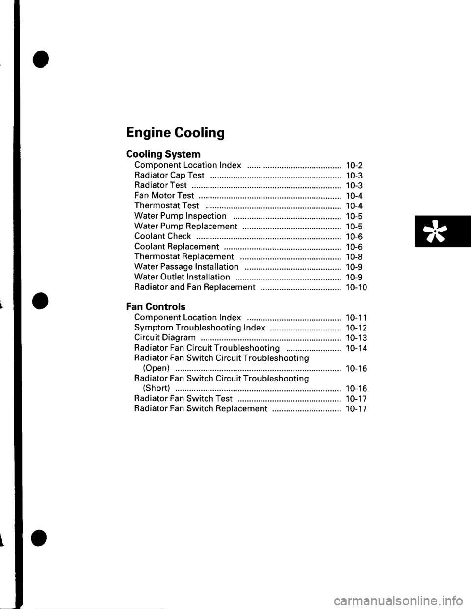
Cooling System
Component Location Index ......................................... 10-2
Radiator Cap Test ..................... .......... 10-3
RadiatorTest ............. 10-3
Fan Motor Test .......... l0-4
Thermostat Test ...................... ........... 10-4
Water Pump Inspection ..................... 10-5
Water Pump Replacement ................. 10-5
Coolant Check .............. ....................... 10-6
Coolant Replacement ......................... 10-6
Thermostat Replacement .................. 10-8
Water Passage Installation ................ 10-9
Water Outlet Installation .................... 10-9
Radiator and Fan Replacement ................................... 10-10
Fan Controls
Component Location Index ......................................... 10-11
Symptom Troubleshooting Index ............................... 10-12
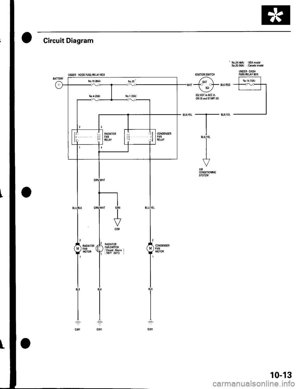
Circuit Diagram ......... 10-13
Radiator Fan CircuitTroubleshooting ........................ 10-14
Radiator Fan Switch Circuit Troubleshooting
(Open) ............ ........ 10-16
Radiator Fan Switch Circuit Troubleshooting
(Short) ............ ........ 10-16
Radiator Fan Switch Test ................... 10-17
Radiator Fan Switch Reolacement .............................. 10-17
Page 203 of 1139
oCircuit Diagram
UIIDEF HOOD FJSE/NILAY BOX
' No.20loA) : USA moddNo.20l50A) : Cm.de mod.l
UNDEN DASXFUSE/RELAY BOX
lG2H0TiiAClill,0N{lllrndSTABI llll)
10-13
Page 238 of 1139
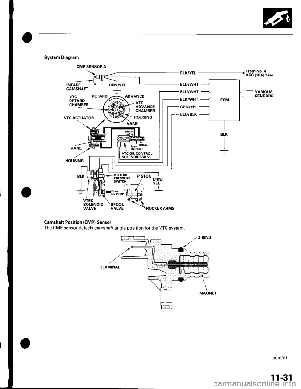
System Diagram
INTAKE
CMP SENSOR A
BRN/YELBLU/WHT
BLU/WHT
BLK/WHT
GRN/YEL
BLU/BLK
From No. ilACC {10A) fuse
VARIOUSSENSORS
CAMSHAFT -:-
BLK
It
Camshaft Position {CMP} Sensor
The CMP sensor detects camshaft angle position for the VTC system.
{cont'd}
11-31
:5i.T,""
Page 239 of 1139
Fuel and Emissions Systems
(
{
System Descriptions (cont'd)
ldle Control System
When the engine is cold, the Ay'C compressor is on, the
transmission is in gear, the brake pedal is pressed. thepower steering load is high, or the alternator is
charging, the ECIM controls current to the ldle Air
Control (lAC) valve to maintain the correct idle speed.
Refer to the System Diagram to see the functional
layout of the system.
Brake Pedal Position Switch
The brake pedal position switch signals the ECM when
the brake pedal is oressed.
Electrical Power Steering (EPS) Senser
The EPS sensor signals the ECM when the power
steering load is high.
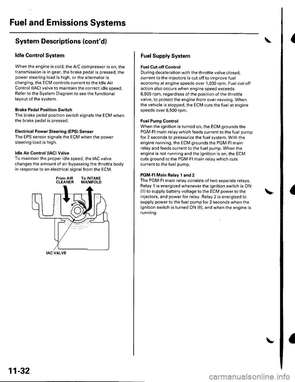
ldle Air Control llACl Valve
To maintain the proper idle speed, the IAC valve
changes the amount of air bypassing the throttle body
in response to an electrical signal from the ECM.
From AIR To INTAKECLEANER MANIFOLD
IAC VALVE
11-32
Fuel Supply System
Fuel Cut-off Control
During deceleration with the throttle valve closed,
current to the injectors is cut off to improve fuel
economy at engine speeds over 1,030 rpm. Fuel cut-off
action also occurs when engine speed exceeds
6,900 rpm, regardless of the position of the throttle
valve, to protect the engine from over-rewing. When
the vehicle is stopped. the ECM cuts the fuel at engine
speeds over 6,500 rpm.
Fuel Pump Control
When the ignition is turned on, the ECM grounds the
PGM-Fl main relay which feeds current to the fuel pump
for 2 seconds to pressurize the fuel system, With the
engine running. the ECM grounds the PGM-Fl main
relay and feeds current to the fuel pump. When the
engine is not running and the ignition is on, the ECI\4
cuts ground to the PGM-Fl main relay which cuts
current to the fuel pump.
PGM-FI Main Relay 1 and 2
The PGM-Fl main relay consists of two separate relays.
Relay 1 is energized whenever the ignition switch is ON(ll) to supply battery voltage to the ECM power to the
injectors, and power for relay, Relay 2 is energized to
supply power to the fuel pump for 2 seconds when the
ignition switch is turned ON (ll), and when the engine is
runnrng.