fuel filter HONDA CIVIC 2002 7.G User Guide
[x] Cancel search | Manufacturer: HONDA, Model Year: 2002, Model line: CIVIC, Model: HONDA CIVIC 2002 7.GPages: 1139, PDF Size: 28.19 MB
Page 357 of 1139
Fuel Supply System
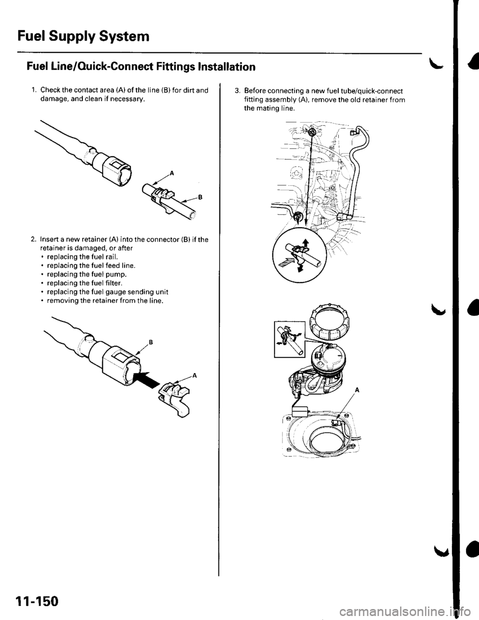
Fuel Line/Ouick-Connect Fittings lnstallation
1. Check the contact a rea (A) of the line (B) for dirt and
damage, and clean if necessary.
Insert a new retainer (A) into the connector (B) if the
retainer is damaged, or after. replacing the fuel rail.. replacing the fuelfeed line.. replacing the fuel pump.. replacing the fuel filter.. replacing the fuel gauge sending unit. removing the retainer from the line.
11-150
3. Before connecting a new fueltube/quick-connect
fitting assembly (A), remove the old retainer from
the matino line,
Page 359 of 1139
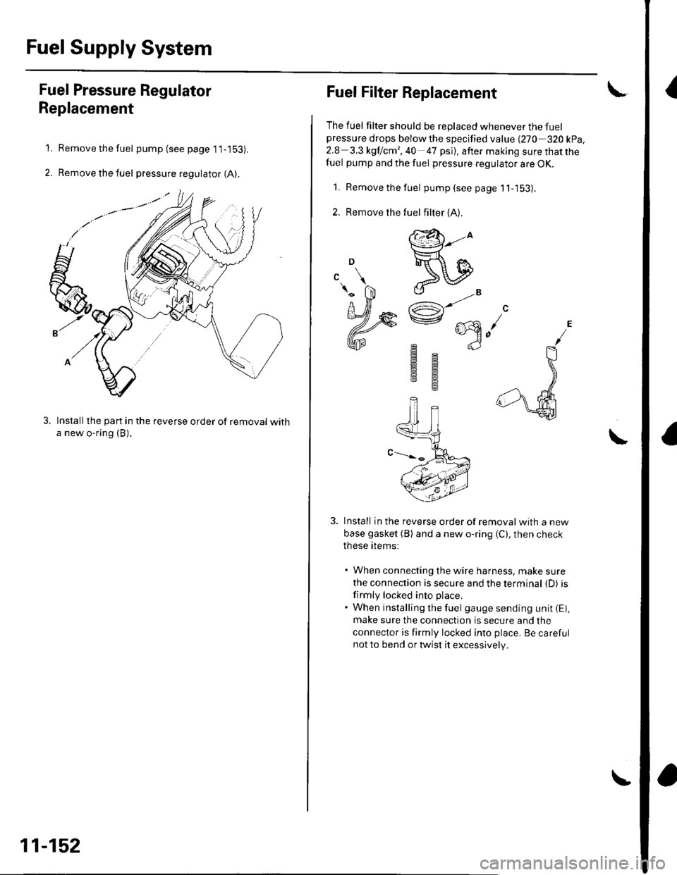
Fuel Supply System
{Fuel Pressure Regulator
Replacement
Remove the fuel pump (see page 1 1-153).
Remove the fuel pressure regulator (A).
Installthe part in the reverse order of removal witha new o-ring (B).
1.
2.
11-152
Fuel Filter Replacement
The fuel filter should be replaced whenever the fuelpressure drops belowthe specified value {270 320 kpa,2.8 3.3 kgf lcm', 40 47 psi), after making sure that thefuel pump and the fuel pressure regulator are OK.
1. Remove the fuel pump(seepagell-'153).
2. Remove the
Install in the reverse order of removalwith a new
base gasket (B) and a new o-ring (C), then check
these items:
' When connecting the wire harness, make sure
the connection is secure and the terminal (D) is
firmly locked into place.. When installing the fuel gauge sending unit iE),make sure the connection is secure and the
connector is firmly locked into place. Be carefulnot to bend or twist it excessively.
\
fuel filter (A).
@-to
ReIJ
e"^AR^ ...\e @n-)
gs
sg
Page 360 of 1139
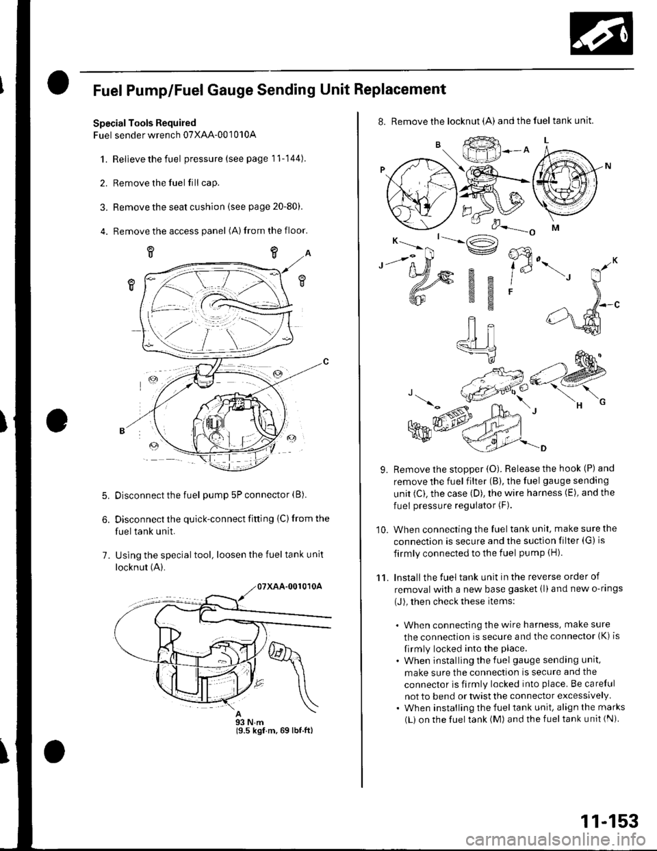
Fuel Pump/Fuel Gauge Sending Unit Replacement
SpecialTools Required
Fuel sender wrench 07XAA-001010A
1.Relieve the fuel pressure (see page 11-144).
Remove the fuel fill cap.
Remove the seat cushion (see page 20-80).
Remove the access panel (A)from the floor.
5.
7.
Disconnect the fuel pump 5P connector (B).
Disconnect the quick-connect fitting {C) from the
fuel tank unit.
Using the special tool, loosen the fuel tank unit
locknut (A).
93 N.m19.5 kgf.m,69 lbf.ftl
11-153
8. Remove the locknut (A) andthefuel tankunit.
9. Remove the stopper {O). Release the hook (P) and
remove the fuel filter (B), the fuel gauge sending
unit (C). the case (D), the wire harness (E), and the
fuel pressure regulator (F).
10. When connecting the fuel tank unit, make sure the
connection is secure and the suction filter (G) is
firmly connected to the f uel pump (H).
11. Install the fuel tank unit in the reverse order of
removal with a new base gasket (l)and new o-rings
(J), then check these items:
. When connecting the wire harness, make sure
the connection is secure and the connector (K) is
firmly locked into the place.
. When installing the f uel gauge sending unit,
make sure the connection is secure and the
connector is firmly locked into place. Be careful
not to bend or twist the connector excessively.. When installing the fueltank unit, align the marks
(L) on the fuel tank (M) and the fuel tank unit (Ni
Page 385 of 1139
EVAP System
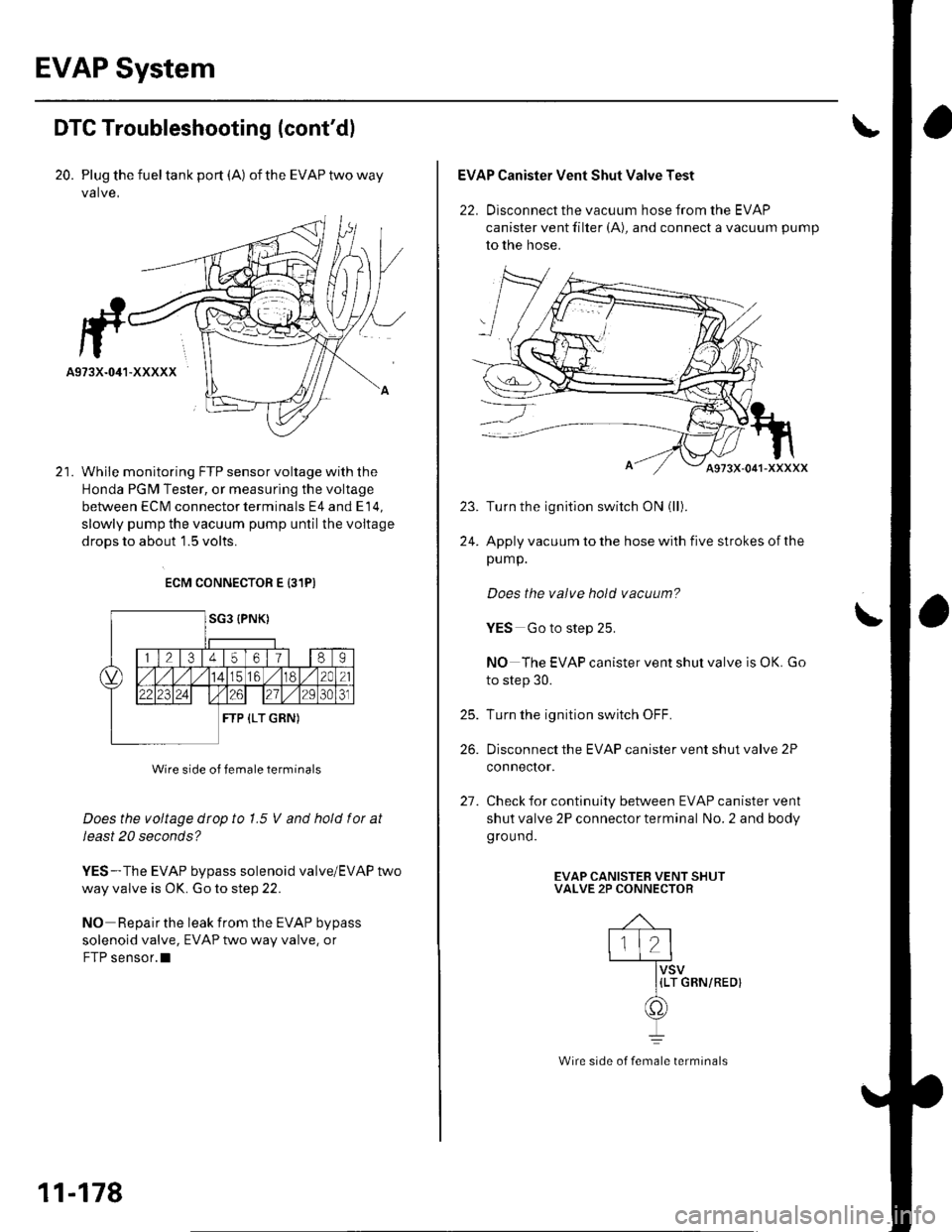
DTC Troubleshooting (cont'dl
20. Plug the fueltank port (A) oftheEVAPtwoway
valve,
While monitoring FTP sensor voltage with the
Honda PGM Tester, or measuring the voltage
between ECM connector terminals E4 and E 14,
slowly pump the vacuum pump until the voitage
droDS to about 1.5 volts.
ECM CONNECTOR E {31PI
Wire side of female terminals
Does the voltage dtop to 1.5 V and hold fot at
Ieast 20 seconds?
YES-The EVAP bypass solenoid valve/EVAP two
way valve is OK. Go to step 22.
NO Repair the leak from the EVAP bypass
solenoid valve, EVAP two way valve. or
FTP sensor.l
11-178
Wire side of female terminals
EVAP Canister Vent Shut Valve Test
22. Disconnect the vacuum hose from the EVAP
canister vent filter (A), and connect a vacuum pump
to the hose.
Turn the ignitlon switch ON (ll).
Apply vacuum to the hose with five strokes of the
pump.
Does the valve hold vacuum?
YES Go to step 25.
NO The EVAP canister vent shut valve is OK. Go
to step 30.
Turn the ignition switch OFF.
Disconnect the EVAP canister vent shut valve 2P
conneclor.
Check for continuity between EVAP canister vent
shut valve 2P connector terminal No. 2 and body
ground.
EVAP CANISTEB VENT SHUTVALVE 2P CONNECTOR
{LT GRN/REOI
\
25.
26.
21.
Page 1135 of 1139
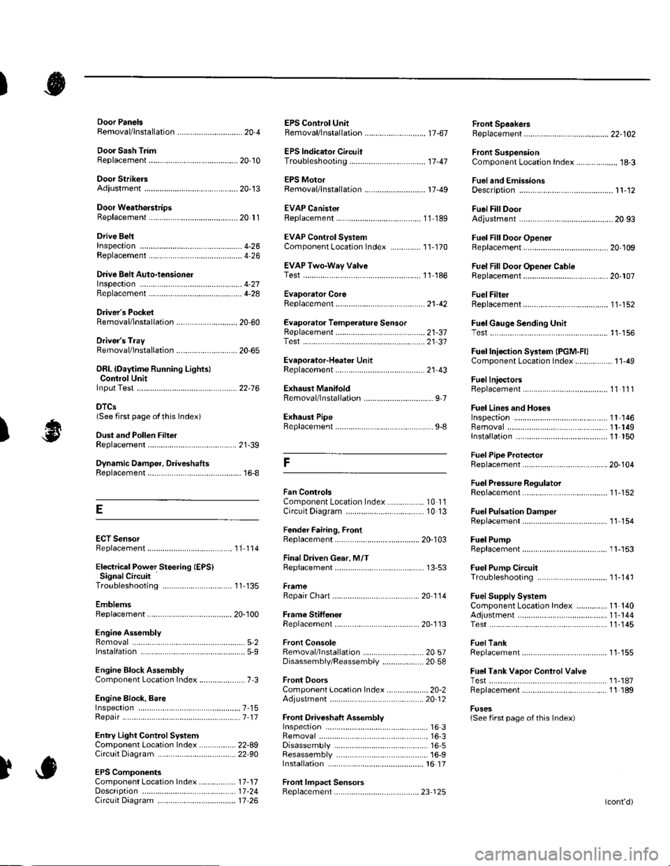
)
Orive BehInspecaron................ 4-26
Door PanelsRemoval/lnstallation -............................. 20-4
Door Sash TrimRep1acement......................................... 20 10
Door StrikersAdiustment ........................................... 20-13
Door Weatherst psBeplacement...........-............................. 20 1 1
EPS Conirol UnitRemoval/1nsta11ation ..................-......... 17-67
EPS Indicator CircuitTroubleshooting ................................... 17 -47
EPS MotorRemoval/lnstallation .-.......................... 17-49
EVAP CanisterRep1acement......................... ......... 11,189
EVAP Control Syst€mComponentLocation Index ..............'11-170
EVAP Two-Wey ValveTest ..........-.............-............................ 11 186
Evaporetor CoreRep1acement........................ . ... 21-42
Evaporator Tomperature SensorReplacement......................................... 21 -37Test..................................... ..........2137
EvaporrtoFHeater UnitReplacement........................................ 21 43
Exhaust ManifoldRemoval/1nsta11ation ................................ I 7
Exhaust Pipe8ep|acement............................................. 9-8
Front SpeakersRep|acement....................................... 22-102
Front SuspensionComponentLocation Index................... 18-3
Fueland EmissionsDescription ........................................... 11-12
Fuel Fill DoorAdjustment ..........-................................ 20 93
Fuel Fill Door OpenetBeplacement........................ . ............ 20.109
Fuel Fill Door Opener CableReplacement....................................... 20- lO7
Fuel FilterReplacement....................................... 1 1-152
Fuel Gauge Sending UnitTest ......................-.-..........-.................. 11'156
Fuel Injection Syslem (PGM"FIlComponent Location 1ndex................. 11-49
Fuel IniectorsRep1acemen1....................................... 1 1 1 1 l
Fuel Lines and HosesInspection .......................................... 1 1'146Removal ....................... . .. . .... 11-149Insta|1ation .......................................... 1 1 150
FuelPipe ProtectolReplacement....................................... 20-104
Fuel Pressure RegulatotReplacement....................................... 1 1-152
Fuel Pulsation DamperReplacemenl................................... 11 154
Fuel PumpReplacement,,,,,.,.,.,,,.,,,,,,,,,,,,.,.,.,,,..,.. 11-153
Fuel Pump CircuitTroubleshooting -.......-....................... 1 1-141
FuelSupply SystemComponent Location lndex .............. 11 140Adjustment................................... 11-144Test........-...-................. ... ............- 11-145
FuelTankBeplacemenl.............. . ..... .. 11 155
Fuel Tank Vapor ControlValveTest ......................-....... ... . . 11-187Replacement,,.,,...,.,,,.,.,,,,... .. .. 11 189
Fuses{See first page ofthis Index)
)
Rep|acement................. ..................... 4 26
Drive Belt Auto-tensionellnspection ............................................... 4 21Rep1acement.................................... ..4-28
Driver's PocketRemoval/lnstallation -........................... 20-60
Driver's TrayRemoval/lnstallation .........................-.- 20-65
DRL {Daytime Running LightslControl Unitlnput Test .................... ........ . . . ......22-16
DTCs(See first page olthis Index)
Dust and Pollen FillerReplacement......................................... 21-39
Dynamic Damper, DriveshaftsReplacement........................................... 16-8
ECT SensorReplacement.,.,,,.,.,,,,,,,,,,,,,,................ 1 1-1 14
El€ctrical Power Steering IEPS)Signal CircuitTroubleshooting ........ ... .. 11-135
EmblemsReplacement......................-................ 20-100
Engine AssemblyRemova1 .................................................... 5 2Installation ............._.................................. 5-9
Engine Block AssemblyComponent Location Inder ..................... 7.3
Engine Block, BareInspect|onRepair
Fan ControlsComponent Location Index................. 10'l 1Circuit Diagram .. ..... . .. . .................. 10 13
Fender Fairing, FrontReplacement...-................................... 20-103
Final Driven Gear. M/TReplacement.... . . ................................ 13-53
FrameRepair Chan............ ... ....................... 20 11 4
Frame StiffenelReplacement......-................................ 20- J'13
Front ConsoleRemoval/lnstallation ............................ 20 5lDisassembJy/Reassemb|y ................... 20 58
Front DoorsComponent Location Index................... 20-2Adiustment ........................................... 20.12
Front Driveshaft AssemblyInspeclion .................... ... ....16 3Remova1...................-...... ... .....16-3Disassembly ............................... .....165Resassemb|y ................................-......... 16-9Insta11arion ........................ ...... ............ l6 17
Front lmpact SensorsRep1acement............................ ...23 125
................7-15................1 11
)
Entry Light Control SystemComponent Location Index ...............-. 22-89Circuit Dia9ram .................................... 22 90
EPS ComponentsComponent Location 1ndex..........-...... 17-!7Description ........................ ...... ..17-24Circuit Diagram11 26(cont'd)
Page 1137 of 1139
)
Low Fuel lndicatorTest.....................11-158Moonroof Drain Channel SliderReplacement......................................... 20'44
Moonroof FrameRep1acement,,,,,,,,,,.,.,.,.,.,.,.,,,,,,............ 20 42
MoonroolGlassAdiustment ........................................... 20-37Rep1acement......................................... 20 37
Moonroot Limit SwitchAdjustment ........................................-.- 20 46Test ...................................................... 22 113
Moonrool MotorReplacement....-.................................... 2D-41
Oil Pressure SwitchTest ................-.-........-................................ 8-4Replacement.........-................................. 8-16
Oil Pump, EngineOverhau1 ................................................... 8-8
Oil, EngineReplacement...-................-.-...................... 8-5
OPDS UnitReplacement....................................... 23- 124
Outside Mirror HoldersBeplacement......................................... 20-15
Outside Power Mirror ActuatorsTest ...................................................... 22-117Bepf acement..-.................................... 22-1 14
Outside Power Mirror SwitchTest ..-................................................... 22-111
Outsid€ Power MirrorsReplacement............................ ... .. . . . 20-15Component Location lndex .............. 22- 114Circuit Diagram .................................. 22-115Test -..................................................... 22-116
Lower ArmsRemoval/1nsta11ation............................ 18 19
Lubrication SystemComponent Location Index..................... 8-3Test............................................................ 8 4
M
M/TAssemblyRemoval.......... 13-4 Test...................... 22-1 12lnstallation............. 13-8
.........21,35
Disassembly ......................................... 13-14Resassembly .. ... ................. 13-46
M/TChange Leverlnspection ............................................. 13-19Disassembly 8eassemb1y ................... 13-20
M/T Countershaft AssemblyInspection ....................................... 13 31, 33Disassemb1y ......................................... 13-32Resassemb|y ........................................ 13-34
M/T DifferentialComponentLocation Index................. 13-52Adiuslment ........................................... 13-56
M/T Maifthaft Assembly1nspection ... ................................... 13-23, 26Disassembly ......................................... 13 25Resassembly ........................................ 13 28Adjustment ........................................... 13-43
M/T Reverse Shift ForkInspection .................... ........................ l3 19
M/T Shift LevelReplacement......................................... 13-51
Mainshaft BearingsReplacement....,.................................... 13 41
MairtenancelSee section 3)
MILHow to Informatron ............................. 1 1.46
MIL CircuitTroubleshooting .......... .- . . . . ......... 11 97
MirrorsComponentLocation Index................. 20'14
Mode Control MotorReplacement
Moonrool SunshadeRep1acement....................... . . ............. 20 40
Moonroof SwitchTesVRep1acement .............................. 22- l 12
Mooniool Wind Def lectorReplacement.......................-................. 20-38
Moonroof/SunroofComponent Location Index ... 20-35, 22-108Test ........................................................ 20-48Cf rcuit Diagram .................................. 22- 109
MTFInspection/Rep1acement. .......... ........... 13-3
Muhiplex Control SystemComponentLocation lndex ..............22 168Circuit Diagram .................................. 22-1690escription ......................................... 22-17 1Troubleshooting ................................ 22-17 2
Muliiplex Control Unit, Under-dashInput TestEntry Light Control Sysiem ............. 22-92Keyless Entry/Security AlarmSystern .-....................................... 22-155MultiplexControl System .............22 115Wiper/Washer................................. 22'1 41
NoiseTest,,Reduction Condenser
Parking ErakeInspection Adjustment ........... .............. 19-7
Parking Brake CableRep1acement......................................... 19-26
Parking Erake Switch
P
l
Test ...................... 19-10
Test............................... . ...........2135
Moonroof Auto Stop SwitchosTest ...................................................... 22'113
Moon.oot Control Unillnput Test ............................................ 22-110
Moonroof Drein ChannelBeplacement ... . ....... ......................... 20 39
Oil Filte]Replacement............................................. 8-6
Oil Filter Feed PipeReplacement............... . ..-,...,.,,,,,,,,8-7
Oil PanRemoval .............,.,,,,,,,,,,,,.,.,,,.........-....... 7 1 1lnstallation .............................................. 7 -27
Passenger's TraVRemoval/lnstallation ............................ 20-65
PCV ValveBeplacement....................................... 1 1'169Test........................................... l1 169
Piston Rings8ep1acement................................-.-...-.- 7-21
PistonsReplacement...................-....................... 7-181nsta|1ation ...................................... ...1-23
Power R€layTest ...............-.-...................................... 22-51
Power Window Motor, Driver'stesl.....,,,, .,.,,,............
Power Window Motors, Passenger's
Power Window Switch, Masterlnput Test ..........-.........-....................... 22-126Tesr ....... . ............................................ 22 124Replacement....................................... 22-133
N
..............22 101
o
l' ,e
(cont'd)