service indicator HONDA CIVIC 2002 7.G Workshop Manual
[x] Cancel search | Manufacturer: HONDA, Model Year: 2002, Model line: CIVIC, Model: HONDA CIVIC 2002 7.GPages: 1139, PDF Size: 28.19 MB
Page 124 of 1139
Gamshaft Inspection
NOTE: Do not rotate the camshaft during inspection.
1. Remove the rocker arm assembly (see page 6-26).
and disassemble it (see page 6-27).
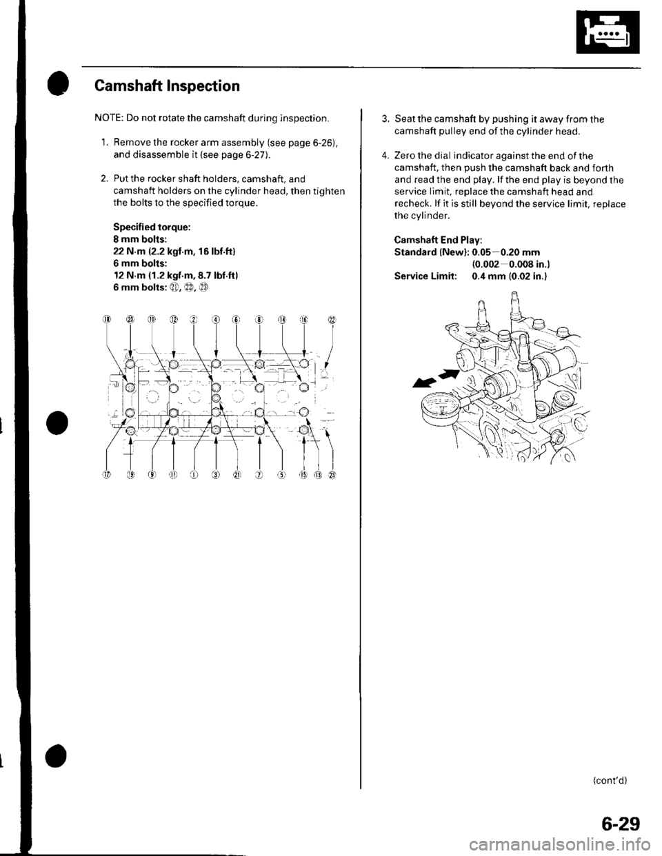
2. Put the rocker shaft holders, camshaft, and
camshaft holders on the cylinder head, then tighten
the bolts to the specified torque.
Specified torque:
I mm bolis:
22 N.m {2.2 kgt m, 16lbf.ft}
6 mm bolts:
12 N.m {1.2 kgf.m,8.7 tbf.ftl
6 mm bolts: @, €0, @
I
I
3. Seat the camshaft by pushing it away from the
camshaft pulley end ofthe cylinder head.
4. Zero the dial indicator against the end of the
camshaft, then push the camshaft back and forth
and read the end play. lf the end play is beyond the
service limit, replace the camshaft head and
recheck. lf it is still beyond the service limit, replace
the cylinder.
Camshaft End Play:
Standard {New}: 0.05 0.20 mm(0.002 0.008 in.l
Service Limit: 0.4 mm (0.02 in.)
(cont'd)
6-29
Page 127 of 1139
Gylinder Head
Valve Inspection
1.Remove the valves (see page 6-31),
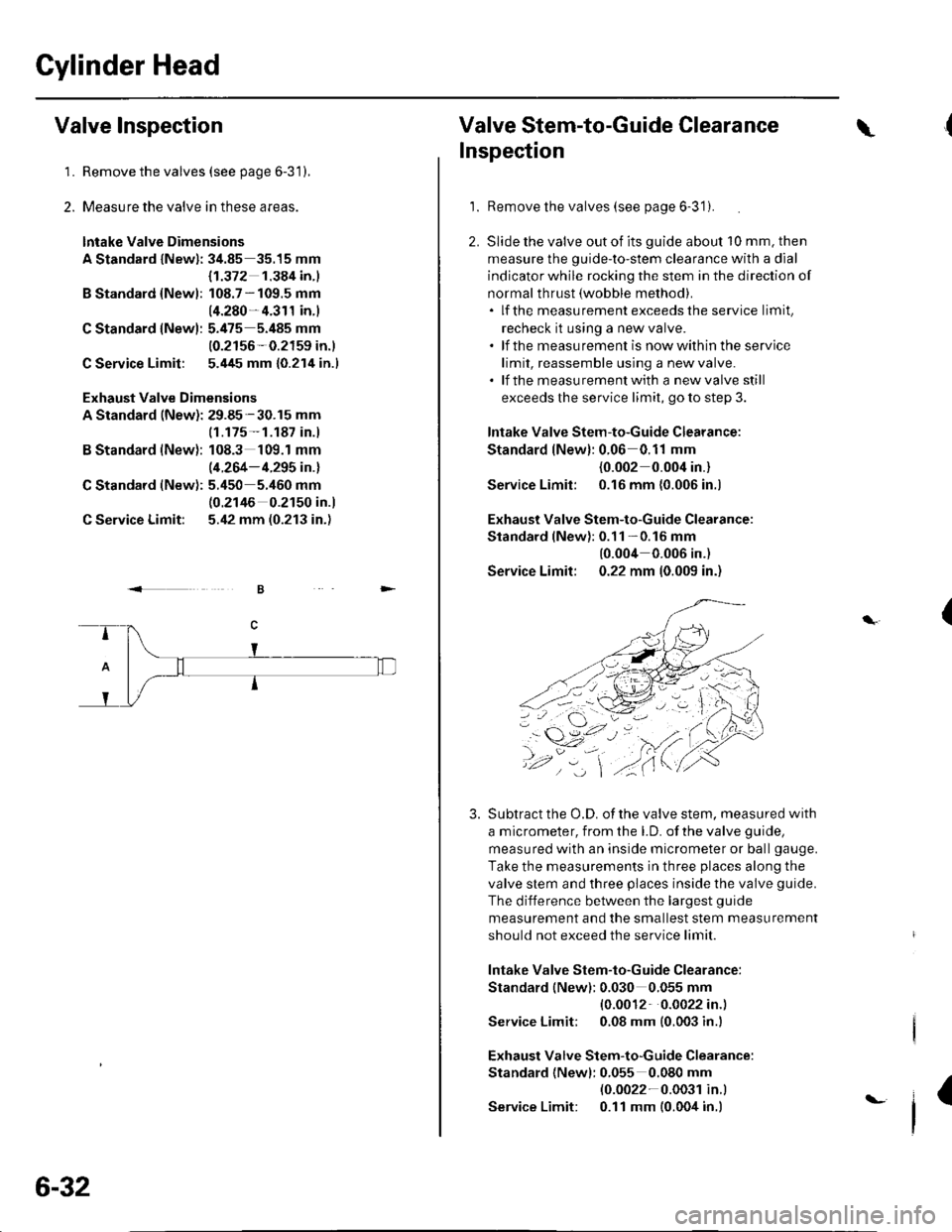
Measure the valve in these areas.
lntake Valve Dimensions
A Standard lNewl: 34.85 35.15 mm
B Standard {Newl:
C Standard lNew):
C Service Limit:
B Standard (New):
C Standard (New):
C Service Limit:
Exhaust Valve Dimensions
A Standard (New): 29.85-30.15 mm
{1.372 1.384 in.l
108.7 - 109.5 mm
14.280- 4.311 in.)
5.475 5.485 mm
10.2156-0.2159 in.)
5.445 mm {0.214 in.l
(1.175- 1.187 in.)
108.3 109.1 mm
(4.264- 4.295 in.l
5.450 5.460 mm(0.2146 0.2150 in.)
5.42 mm (0.213 in.)
2.
.<
6-32
t-
Valve Stem-to-Guide Clearance\
Inspection
1.Remove the valves (see page 6-3'1).
Slide the valve out of its guide about 10 mm. then
measure the guide-to-stem clearance with a dial
indicator while rocking the stem in the direction of
normal thrust (wobble method).. lf the measurement exceedsthe service limit,
recheck it using a new valve.. lf the measurement is nowwithin the service
limit, reassemble using a new valve.. lf the measurementwith a newvalve still
exceeds the service limit, go to step 3.
lntake Valve Stem-to-Guide Clearance:
Standard lNew): 0.06 0.11 mm
{0.002 0.004 in.}
Service Limil: 0.16 mm {0.006 in.)
Exhaust Valve Stem-to-Guide Clearance:
Standard lNewl:0.11 -0.16 mm
10.004 0.006 in.)
Service Limit: 0.22 mm 10.009 in.)
Subtract the O.D. of the valve stem. measured with
a micrometer, from the LD. of the valve guide,
measured with an inside micrometer or ball gauge.
Take the measurements in three places along the
valve stem and three places inside the valve guide.
The difference between the largest guide
measurement and the smallest stem measurement
should not exceed the service limit
lntake Valve Stem-to-Guide Clearance:
Standard (New): 0.030 0.055 mm
{0.0012 0.0022 in.)
Service Limit; 0.08 mm (0.003 in.l
Exhaust Valve Stem-to-Guide Clearance:
Standard {Newl: 0.055 0.080 mm(0.0022-0.003r in.l
Service Limit: 0.11 mm (0.004 in.)
(
3.
4,.
I
Page 143 of 1139
Connecting Rod and Crankshaft End Play Inspection
1.Remove the oil pump (see page 8-9).
Remove the baffle plates (see step 6 on page 1 -12).
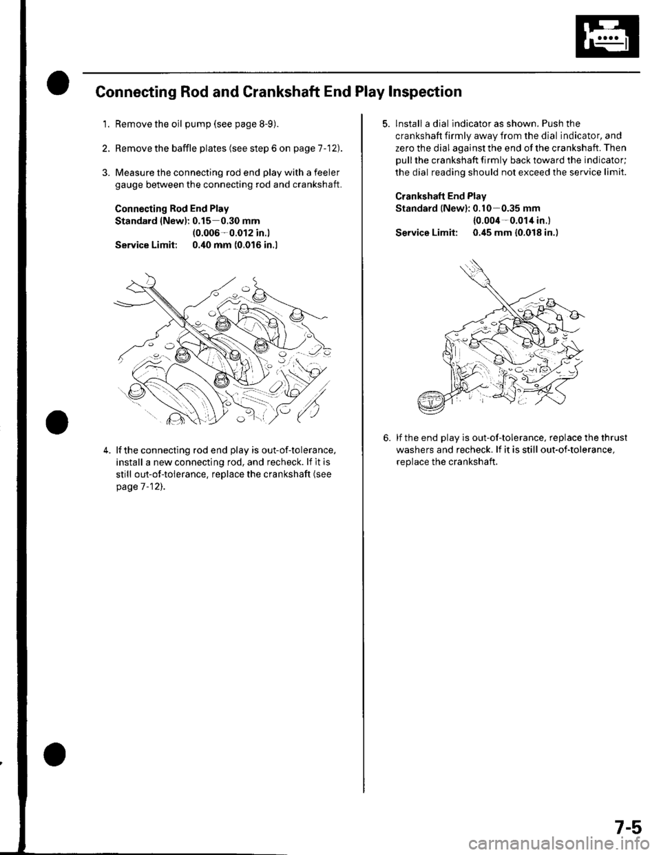
3. Measure the connecting rod end play with a feeler
gauge between the connecting rod and crankshaft.
Connecting Rod End Play
Standard {New): 0.15 0.30 mm(0.006-0.012 in.l
Service Limit 0.40 mm (0.016 in.l
4.lf the connecting rod end play is out-of-tolerance,
install a new connecting rod, and recheck. lf it is
still out-of-tolerance, replace the crankshaft (see
page 7 -12],.
5. lnstall a dial indicator as shown. Push the
crankshaft firmly away from the dial indicator, and
zero the dial against the end of the crankshaft. Then
pull the crankshaft firmly back toward the indicator;
the dial reading should not exceed the service limit.
Crankshaft End Plav
Standard lNew): 0.10-0.35 mm
{0.004-0.014 in.l
Service Limit: 0.45 mm {0.018 in.)
lf the end play is out-of-tolerance, replace the thrust
washers and recheck. lf it is still out-of-tolerance,
replace the crankshaft.
7-5
Page 157 of 1139
v
Inspection
NOTE: Inspect the piston, piston pin, and connecting
rod when they are at room temperature.
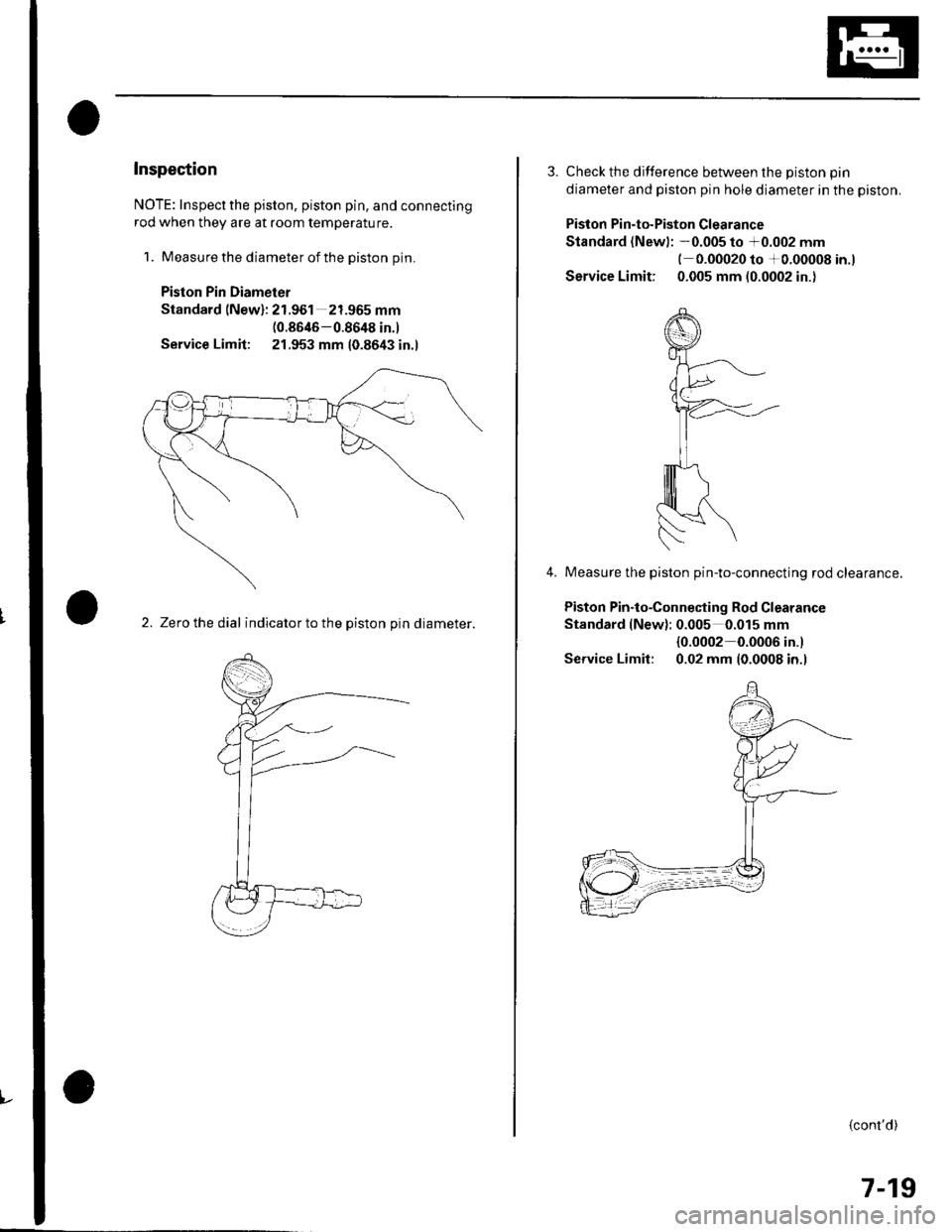
1. Measure the diameter of the piston pin.
Piston Pin Diameter
Standard (New): 21.961 21.965 mm(0.8646-0.8648 in.)
Service Limit: 21.953 mm 10.8643 in.l
2. Zerc the dial indicator to the piston pin diameter.
3. Check the difference between the Diston Din
diameter and piston pin hole diameter in the piston.
Piston Pin-to-Piston Clearance
Standard (Newl: -0.005 to +0.002 mm(-0.00020 to +0.00008 in.)
Service Limit: 0.005 mm (0.0002 in.)
Measure the piston pin-to-connecting rod clearance.
Piston Pin.to-Connecting Rod Clearance
Standard (New): 0.005 0.015 mm
{0.0002 0.0006 in.}
Service Limil: 0.02 mm (0.0008 in.l
4.
(cont'd)
7-19
Page 177 of 1139
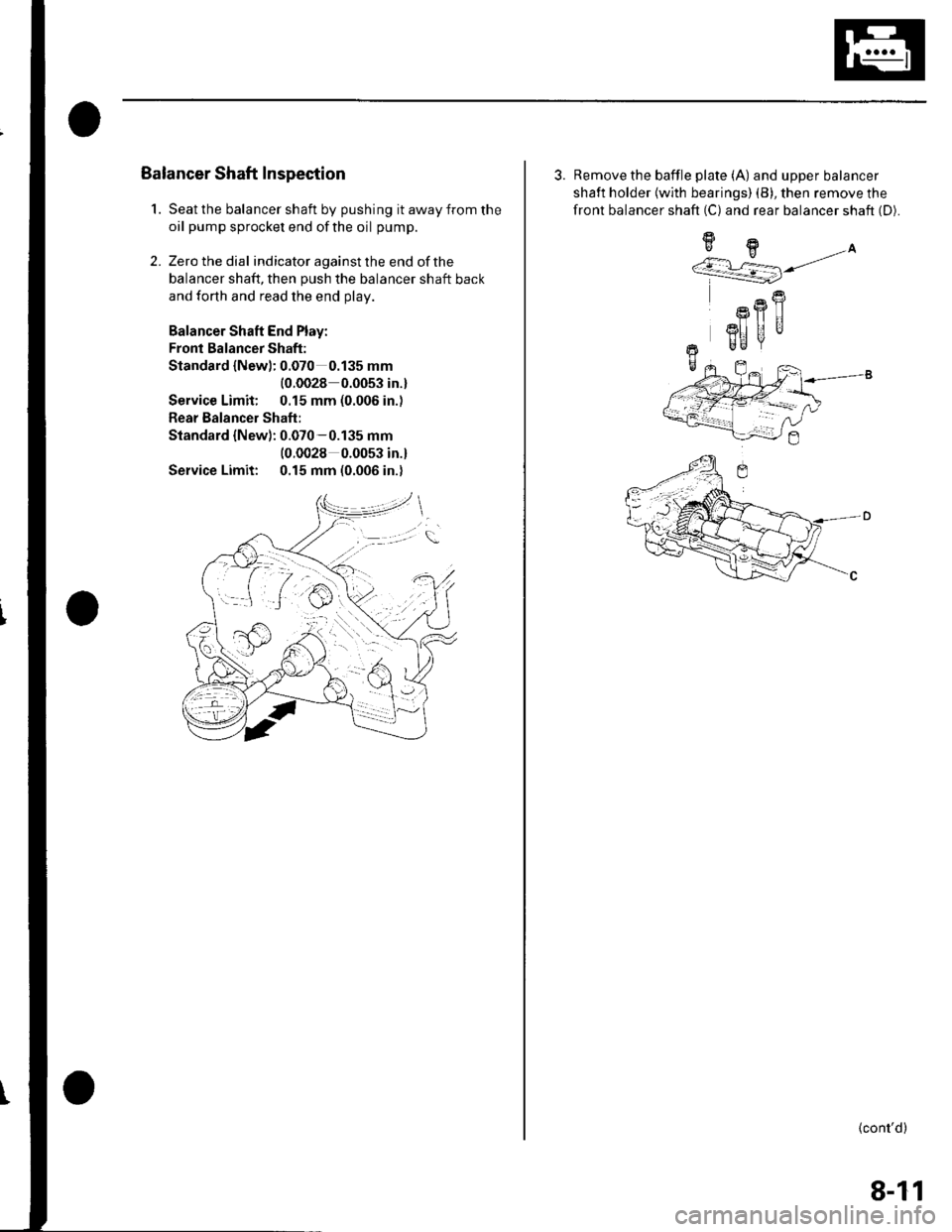
1.
Balancer Shaft Inspection
Seat the balancer shaft by pushing it away from the
oil pump sprocket end ofthe oil pump.
Zero the dial indicator against the end of the
balancer shaft, then push the balancer shaft back
and forth and read the end olav.
Balancer Shaft End Play:
Fronl Balancer Shaft:
Standard {Newl: 0.070 0.135 mm
{0.0028 0.0053 in.}
Service Limit: 0.15 mm (0.006 in.)
Rear Balancer Shaft:
Standard {New): 0.070-0.135 mm(0.0028 0.0053 in.l
Service Limit: 0.15 mm (0.006 in.)
2.
3. Remove the baffle plate (A) and upper balancer
shaft holder {with bearings) (B), then remove the
front balancer shaft (C) and rear balancer shaft (D).
9H.A''/.r L=] j/
R
Rfl|]
3I] UUr Be
+-
(cont'd)
8-11
Page 214 of 1139
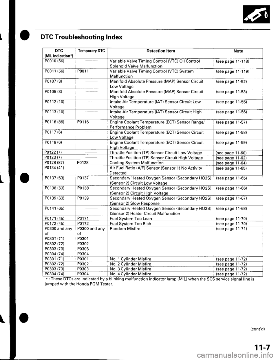
DTC Troubleshooting Index
";These DTCs are indicated by a blinking malfunction indicator lamp (MlL)when the SCS service signal line isjumped with the Honda PGM Tester.
{cont'd)
11-7
DTC
{MlL indication*)
Temporary DTCDetection ltemNote
P0010 (56)Variable Valve Timing Control {VTC) Oil Control
Solenoid Valve Malfunction
{see page 1 1'1 18)
P0011 (56)P001 1Variable Valve Timing Control (WC) System
Malfunction
(see page 11- 1 19)
P0107 (3)Manifold Absolute Pressure (MAP) Sensor Circuit
Low Voltaqe
(see page 1'l-521
P0108 (3)Manifold Absolute Pressure (MAP) Sensor Circuit
Hiqh Voltaqe
(see page 11-53)
P0112 (10)Intake Air Temperature (lAT) Sensor Circuit Low
Voltaoe
(see page 11-55)
P01r3 (10)Intake Air Temperature (lAT) Sensor Circuit High
Voltaoe
(see page '11-56)
P0116 {86) P0116Englne Coolant Temperature (ECT) Sensor Range/
Performance Problem
{see page 11-57)
P0117 {6)Engine Coolant Temperature (ECT) Sensor Circuit
Low Voltaqe
(see page 11-58)
P0118 {6)Engine Coolant Temperature (ECT) Sensor Circuit
Hiqh Voltaqe
{see page 11-59)
P0122 t7\Throttle Position (TP) Sensor Circuit Low Voltaqe(see Daqe 11-60)P0123 {7)Throttle Posltion (TP) Sensor Circuit Hiqh Voltaoe(see paqe 11-62)
P0128 (87)P0128Coolinq SVStem Malfunction(see Daqe 11-64)
P0134 (41)Air Fuel Ratio (Ay'F) Sensor (Sensor 1) No Activity
Detected
(see page 11-65)
P0137 (63)P0137Secondary Heated Oxygen Sensor (Secondary HO2S)(Sensor 2) Circuit Low Voltaqe
(see page 11-65)
P0138 (63)P0138Secondary Heated Oxygen Sensor (Secondary HO2S)(Sensor 2) Circuit Hiqh Voltaqe
(see page 11-66)
P0139 (63)P0139Secondary Heated Oxygen Sensor (Secondary H02S)(Sensor 2) Slow ResDonse
(see page 11-67)
P0141 (65)Secondary Heated Oxygen Sensor (Secondary H02S)(Sensor 2) Heater Circuit Malfunction
(see page 11-68)
P0171 (45)PO\11Fuel Svstem Too Lean(see paqe 11-70)
PO112 l'45)PO\l2Fuel System Too Rich(see oaoe 11-70)
P0300 and any P0300 and any
of of
P0301 (71) P0301
PO302 (721 P0302
P0303 (73) P0303
P0304 (74) P0304
Random Misfire(see page 11-71)
P0301 (7'1) P0301No. 1 Cylnder Misfire{see page 11-72)
P0302 (721 P0302No. 2 Cvlnder Misfire{see paqe 1 1-72)
P0303 (73)P0303No. 3 Cvlnder Misfire(see oaqe 11-72)
P0304 {74)P0304No. 4 Cvlnder Misfire{see Daqe 1 1-72)
Page 230 of 1139
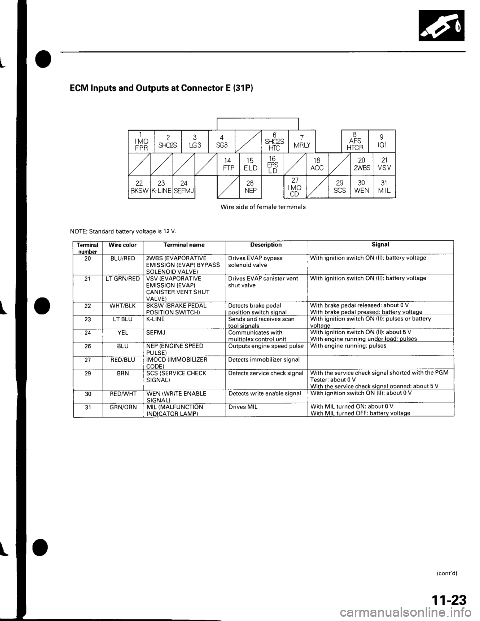
ECM Inputs and Outputs at Connector E (31P)
ltMoFPR
2$.c2s
i6SFIO2SHTC
1
IV RLY
IAFSHTCR
9tGl
14FTP15ELD
16EPSLD
t8202,4/BS21VSV
22BKSW23K LINE24SEFMJ26NEP
21lvoCD
29scs30WEN31MIL
Wire side of female terminals
NOTE: Standard battery voltage is 12 V.
TerminalWire colorTerminalnameDescriptionSignal
20BLU/RED2WBS (EVAPORATIVEEMISSION (EVAP)BYPASSSOLENOID VALVE)
Drives EVAP bypass With ignition switch ON (ll): baftery voltagesolenoid valve
21LT GRN/REDVSV (EVAPORATIVE
EI\4ISSION iEVAP)CANISTEB VENT SHUTVALVE)
Drives EVAP canister ventshut valveWith ignilion switch ON (ll): battery voltage
22WHT/BLKBKSW lBRAKE PEDALPOSITION SWITCH)Detects brake pedaloosition switch sionalWith brake pedal released: about 0 VWith hrake nedal nresse.l: batterv voltaoe23LT BLUK-LIN ESends and receives scanWith ignition switch ON (li)r pulses or battery
YELSEFMJCommunicates withmrltinleY eontrol unitWith ignition switch ON (ll): about 5 VWith enoine runnino under load: DUlses26BLUNEP (ENGINE SPEEDPULSE)Outputs engine speed pulseWith engine running: pulses
21RED/BLU \40CD fl\4MOBTLTZERCODE)Detects imrnobilizer signal
29BRNSCS (SERVICE CHECKSIGNAL)Oetects service check signalWith the service check signal shorted with the PGMTester: about 0 VWiih rhe service check sional ooened: about 5 V
30RED,A/VHTWEN (WRITE ENABLESIGNALiDetects write enable signal With ignition switch ON (ll): about 0 V
GRN/ORNMIL (MALFUNCTION
INDICATOR LAMP)Drives N4lLWith MIL turned ON: about 0 VWith MIL turned OFF: batterv voltaqe
(cont'd)
11-23
Page 408 of 1139
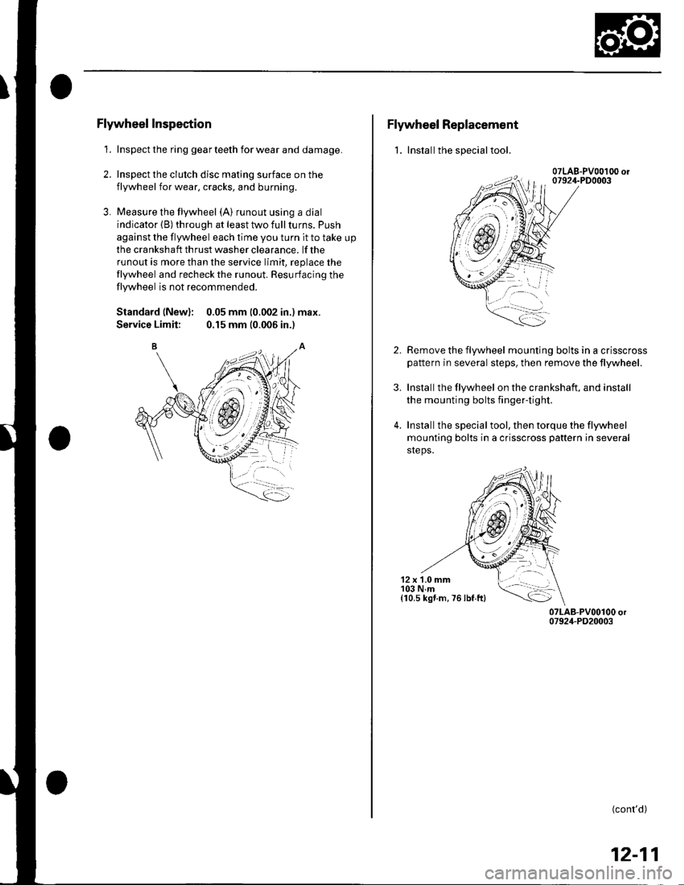
Flywheel Inspection
1. Inspect the ring gear teeth for wear and damage.
2. Inspect the clutch disc mating surface on the
flywheel for wear, cracks, and burning.
3. Measure the flywheel (A) runout using a dial
indicator (B) through at least two full turns. Push
against the flywheel each time you turn it to take up
the cra nksh aft th rust washer clea rance. lf the
runout is more than the service limit, replace the
flywheel and recheck the runout. Resurfacing the
flywheel is not recommended.
Standard (New): 0.05 mm (0.002 in.) max.
Service Limit: 0.15 mm (0.006 in.)
Flywheel Replacement
1. Installthe special tool.
2.
3.
4.
Remove the flywheel mounting bolts in a crisscross
pattern in several steps, then remove the tlywheel.
Installthe flywheel on the crankshaft, and install
the mounting bolts fingertight.
Installthe specialtool, then torque the flywheel
mounting bolts in a crisscross pattern in several
sreps.
12 x 1.0 mm103 N.m(10,s kst.m. 76 lbf ftl
(cont'd)
12-11
Page 433 of 1139
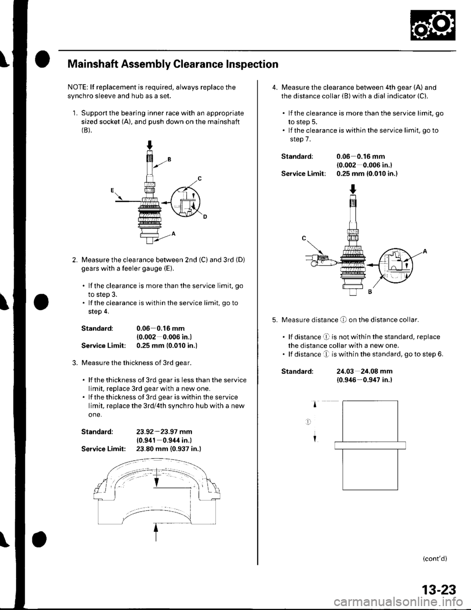
Mainshaft Assembly Clearance Inspection
NOTE: lf replacement is required, always replace the
synchro sleeve and hub as a set.
1. Support the bearing inner race with an appropriate
sized socket (A). and push down on the mainshaft(B).
Measure the clearance bet\iveen 2nd (C) and 3rd (D)
gears with a feeler gauge {E).
. lf the clearance is more than the service limit. go
to step 3.. lf the clearance is within the service limit, go to
step 4.
Standard:0.06 0.16 mm
{0.002 0.006 in.l
Service Limit: 0.25 mm (0.010 in.l
Measure the thickness of 3rd gear.
. lf thethickness of 3rd gearis lessthanthe service
limit, replace 3rd gearwith a new one.. lf thethickness of 3rd geariswithintheservice
limit, replace the 3rd/4th synchro hub with a new
one.
Standard: 23.92-23.97 mm(0.941 0.944 in.)
Service Limit: 23.80 mm (0.937 in.)
4. Measure the clearance between 4th gear (A) and
the distance collar (B) with a dial indicator (C).
. lf the clearance is more than the service limit, go
to step 5.. lf the clearance is within the service limit, go to
step 7.
Standard: 0.06 0.16 mnl(0.002 0.006 in.)
Service Limit: 0.25 mm {0.010 in.)
Measure distance O on the distance co[ar.
. lf distance't is notwithin the standard, replace
the distance collar with a new one.. lf distance e is within the standard, go to step 6.
Standard:24.03 24.08 mm
{0.946-0.9/u in.}
(cont'd)
13-23
Page 434 of 1139
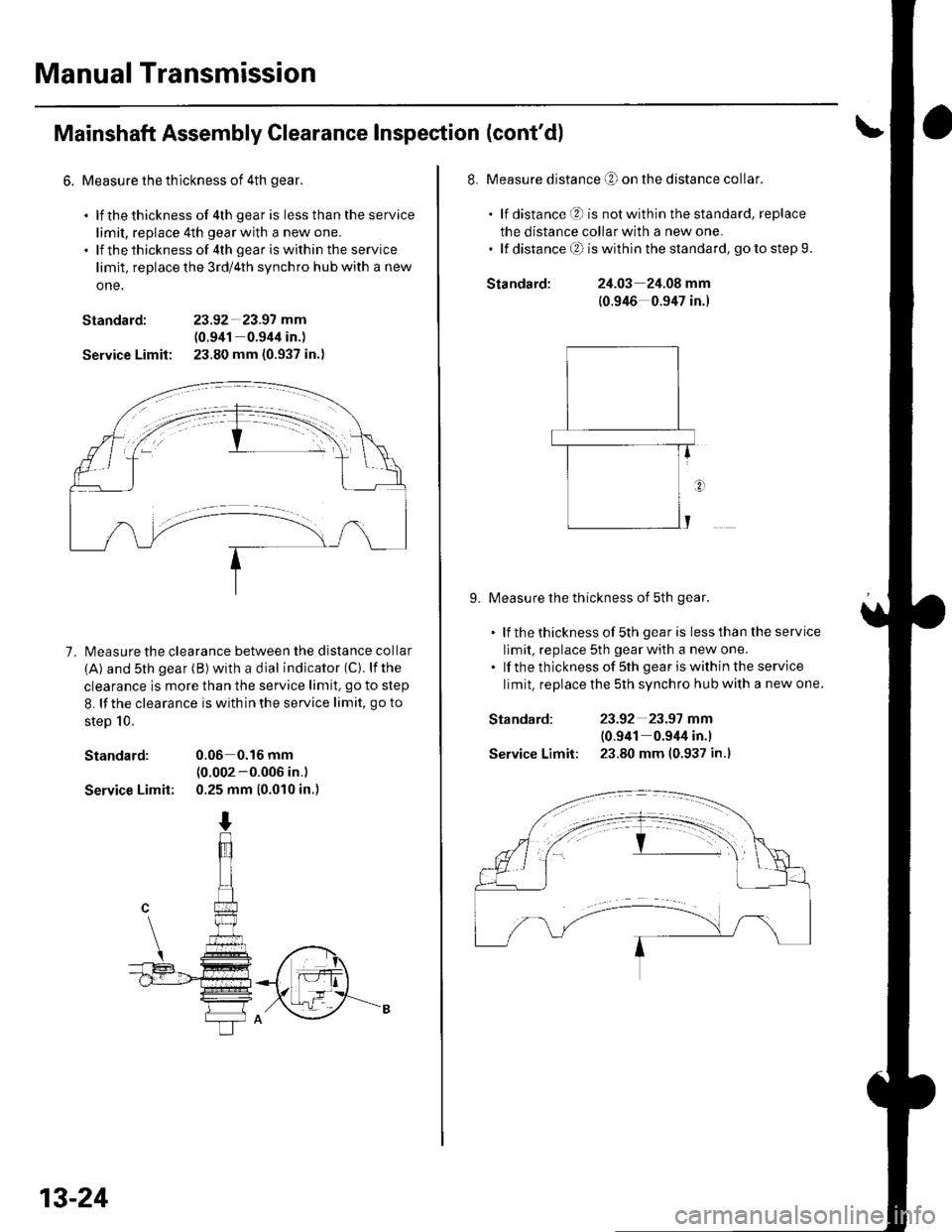
Manual Transmission
Mainshaft Assembly Clearance Inspection (cont'd)
6. Measure the thlckness of 4th gear.
. lf thethickness of 4th gear is lessthantheservice
limit, replace 4th gear with a new one.. lf thethicknessof 4th geariswithin the service
limit. replace the 3rd/4th synchro hub with a new
one.
Standard: 23.92 23.97 mm
(0.941 0.944 in.)
Service Limit: 23.80 mm (0.937 in.)
7. l\4easure the clearance between the distance collar
(A) and sth gear (B) with a dial indicator (C). lfthe
clearance is more than the service limit. go to step
8. lf the clearance is with in the service limit, go to
steD 10.
Standard: 0.06 0.16 mm(0.002-0.006 in.)
Service Limit: 0.25 mm (0.010 in.)
13-24
Standard:
Standard:
Service Limit:
8. Measure distance O on the distance collar.
. lf distance O is notwithinthestandard, replace
the distance collar with a new one.' lf distanceO iswithinthe standard, gotostep9.
24.03 24.08 mm
(0.946 0.947 in.)
9. Measure the thickness of 5th gear.
. lf thethicknessof 5th gearis lessthantheservice
limit, replace 5th gear with a new one.. lf the thickness of sth gear iswithin the service
limit. replace the 5th synchro hub with a new one.
23-92 23.97 mm
10.941 0.944 in.l
23.80 mm (0.937 in.l