ignition HONDA CIVIC 2002 7.G User Guide
[x] Cancel search | Manufacturer: HONDA, Model Year: 2002, Model line: CIVIC, Model: HONDA CIVIC 2002 7.GPages: 1139, PDF Size: 28.19 MB
Page 98 of 1139
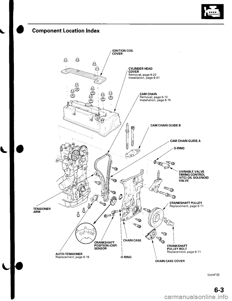
Component Location lndex
TENSIONERARM
AUTO.TENSIONERReplacement, page 6-'l I
IGNITION COILCOVER
CYLINDER HEADCOVERRemoval, page 6-22lnstallation, page 6-41
CAM CHAINBemoval, page 6-'12Installation, page 6-15
frn
|]tJ ,"p
CAM CHAIN GUIDE B
CAM CHAIN GUIDE A
VARIABLE VALVETIMING CONTROLtwc) olL soLENotDVALVE
CRANKSHAFT PULLEYReplacement, page 6 11
O-RING
(cont'd)
6-3
Page 101 of 1139
Cylinder Head
Engine Compression Inspection
1. Warm up the engine to normal operating
temperature (cooling fan comes on).
2. Turn the ignition switch OFF.
3. Remove the intake manifold cover (see step 1 onpage 6-22).
4, Disconnect all four injector connectors.
5. Start the engine, and let it run until it stalls.
6. Remove the iour ignition coils (see page 4-18).
7. Remove the four spark plugs.
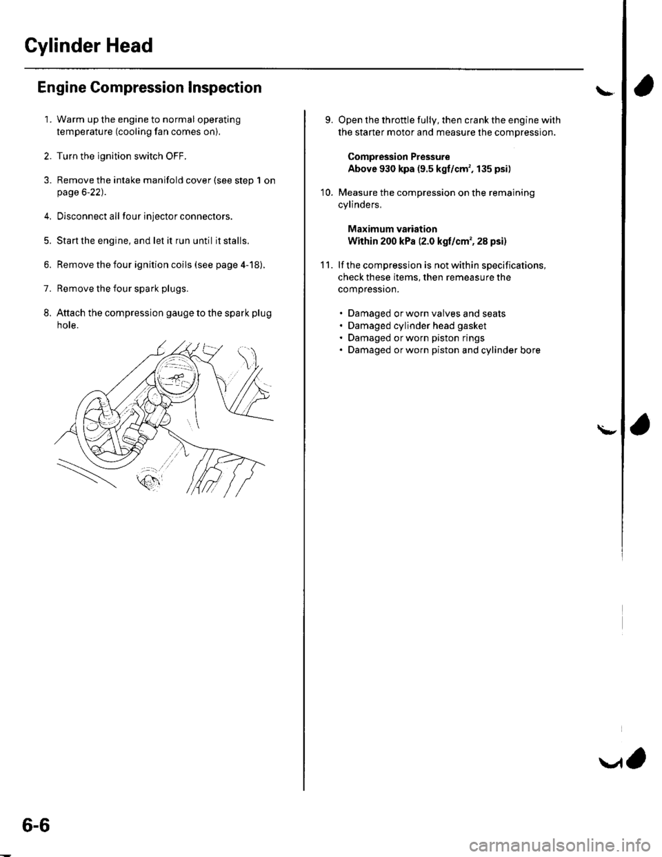
8. Attach the compression gauge to the spark plug
note.
6-6
V,
\
9.
10.
Open the throttle fully, then crank the engine with
the starter motor and measure the compression.
Compression Pressure
Above 930 kpa (9.5 kgf/cm', 135 psi)
Measure the compression on the remaining
cylinders,
Maximum vadation
Within 200 kPa (2.0 kgf/cm', 28 psi)
lf the compression is not within specifications,
check these items, then remeasure the
compressron.
. Damaged orworn valves and seats. Damaged cylinder head gasket. Damaged or worn piston rings. Damaged orworn piston and cylinder bore
11.
\-
Page 117 of 1139
Gylinder Head
Cylinder Head Cover Removal
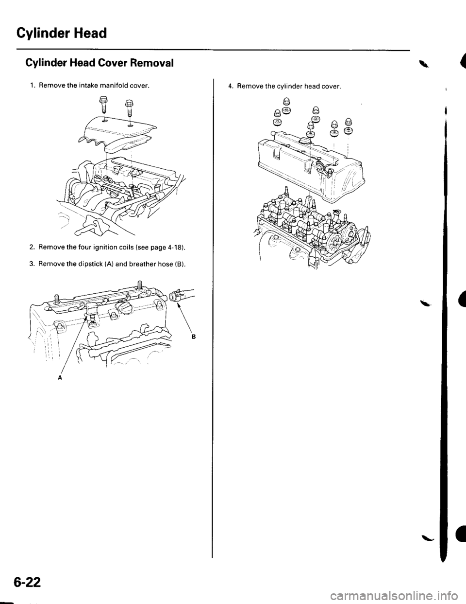
1. Remove the intake manifold cover.
2. Remove the four ignition coils (see page 4-'18).
3. Remove the dipstick (A) and breather hose (B).
6-22
\-
\
4, Remove the cylinder head cover
V:t :;t 1
|
,'.i/
(
(
Page 136 of 1139
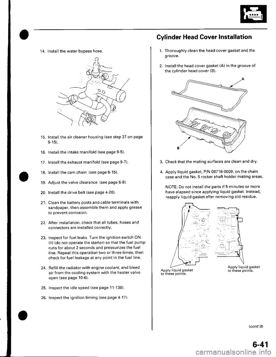
14. Installthe water bvpass hose.
15. Installthe air cleaner housing (see step 37 on page
5-15).
16. Installthe intake manifold (see page 9-5).
17. Installthe exhaust manifold (see page 9-7).
'18. Installthe cam chain (see page 6-15).
19. Adjust the valve clearance (seepage6-9).
20. Installthe drive belt (see page 4-26).
21. Clean the battery posts and cable terminals with
sandpaper, then assemble them and apply grease
to prevent corrosion.
22. After installation, checkthatall tubes, hosesand
connectors are installed correctly.
23. Inspectforfuel leaks. Turn the ignition switch ON
{ll) {do not operate the starter) so that the fuel pump
runs for about 2 seconds and pressurizes the fuel
line. Repeat thls operation two or three times, then
check for fuel leakage at any point in the fuel line.
24. Refillthe radiator with engine coolant, and bleed
air from the cooling system with the heater valve
open (see page 10-6).
25. Inspect the idle speed (see page 11-'138).
26. Inspect the ignition timing (see page 4-17).
Gylinder Head Cover lnstallation
1. Thoroughly clean the head cover gasket and the
groove.
2. Installthe head cover gasket (A) in the groove of
the cylinder head cover (B).
Check that the mating surfaces are clean and dry.
Apply liquid gasket. P/N 08718-0009, on the chain
case and the No.5 rocker shaft holder mating areas.
NOTE: Do not install the parts if 5 minutes or more
have elapsed since applying liquid gasket. Instead,
reapply liquid gasket after removing old residue.
(cont'd)
6-41
Page 138 of 1139
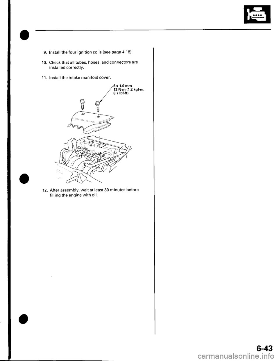
9.
10.
Install the four ignition coils (see page 4-'18).
Check that all tubes, hoses, and connectors are
installed correctly.
lnstallthe intake manifold cover.11.
6x 1,0 mm'12 N.m {1.2 kgf m.8.7 tbf.ftl
12. After assemblv, wait at least 30 minutes before
filling the engine with oil.
6-43
Page 188 of 1139
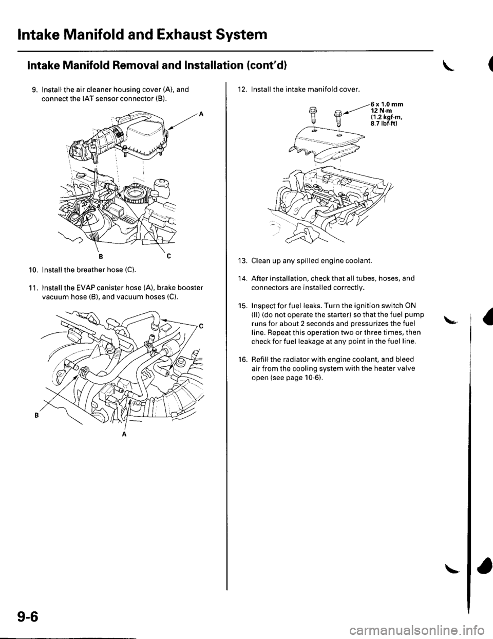
lntake Manifold and Exhaust System
Intake Manifold Removal and Installation (cont'd)
9. lnstallthe air cleaner housing cover (A), and
connect the IAT sensor connector (B).
BC
Installthe breather hose (C).
lnstallthe EVAP canister hose (A), brake booster
vacuum hose (B), and vacuum hoses {C).
10.
11.
9-6
\
12. Installthe intake manifold cover.
6x1.0mm12 N.ml.1.2k91.m,8.7 tbf.ftl
Clean up any spilled engine coolant.
After installation, check that all tubes, hoses, and
connectors are installed correctly.
Inspect for fuel leaks. Turn the ignition switch ON
(ll) (do not operate the starter) so that the fuel pump
runs for about 2 seconds and pressurizes the fuel
line. Repeat this operation two or three times, then
check for fuel leakage at any point in the fuel line.
Refill the radiator with engine coolant, and bleed
air from the cooling system with the heater valve
open (see page 10-6).
to.
\-
Page 196 of 1139
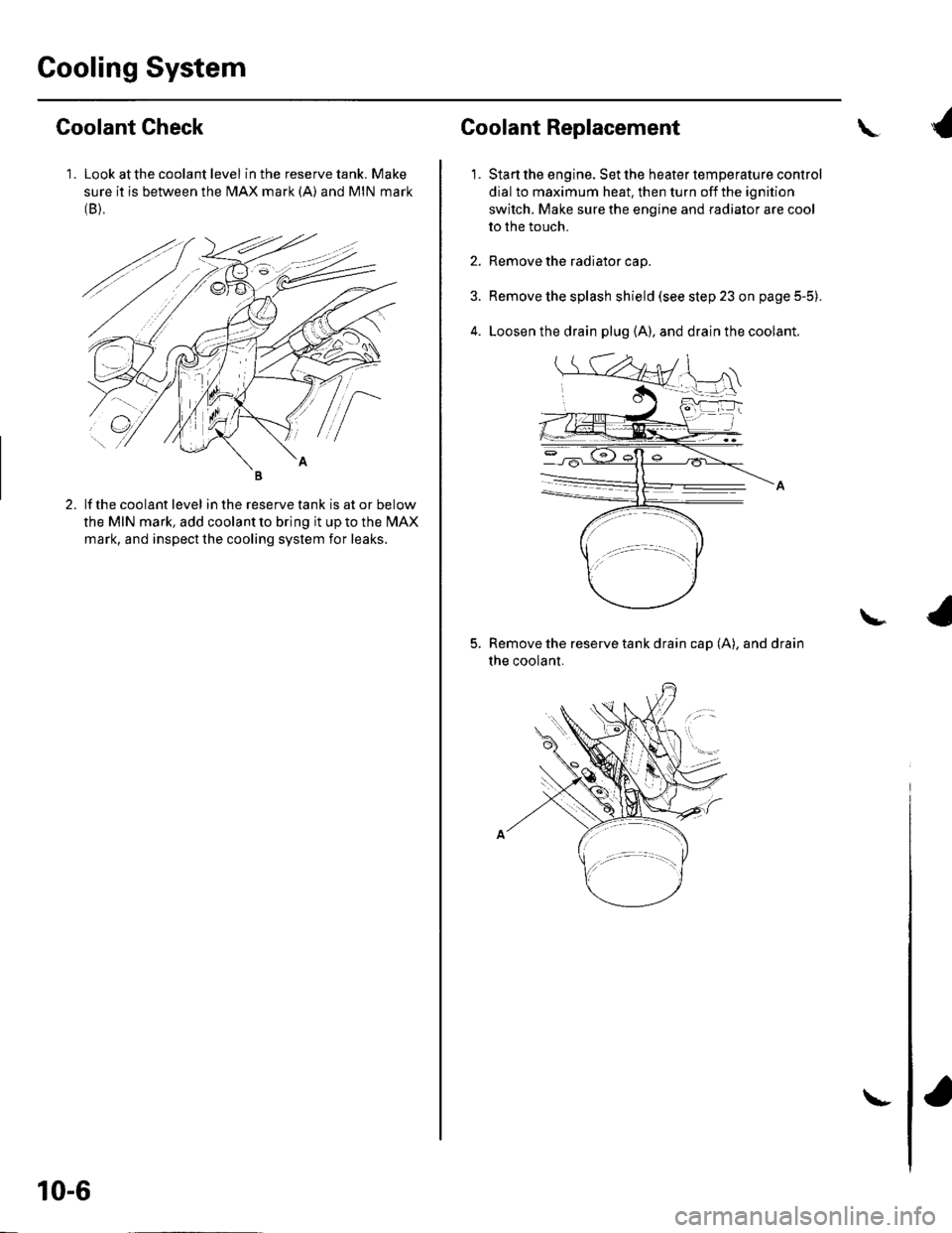
Cooling System
1 . Look at the coolant level in the reserve tank. Make
sure it is between the MAX mark (A) and MIN mark(B),
Goolant Check
lf the coolant level in the reserve tank is at or below
the MIN mark, add coolant to bring it up to the l\4AX
mark, and inspect the cooling system for leaks.
10-6
\-
Coolant Replacement
1.
\
Start the engine. Set the heater temperature control
dial to maximum heat. then turn off the ignition
switch. Make sure the engine and radiator are cool
to the touch.
Remove the radiator cap.
Remove the splash shield (see step 23 on page 5-5).
Loosen the drain plug (A), and drain the coolant.
Remove the reserve tank drain cap (A), and drain
the coolant.
\
Page 202 of 1139
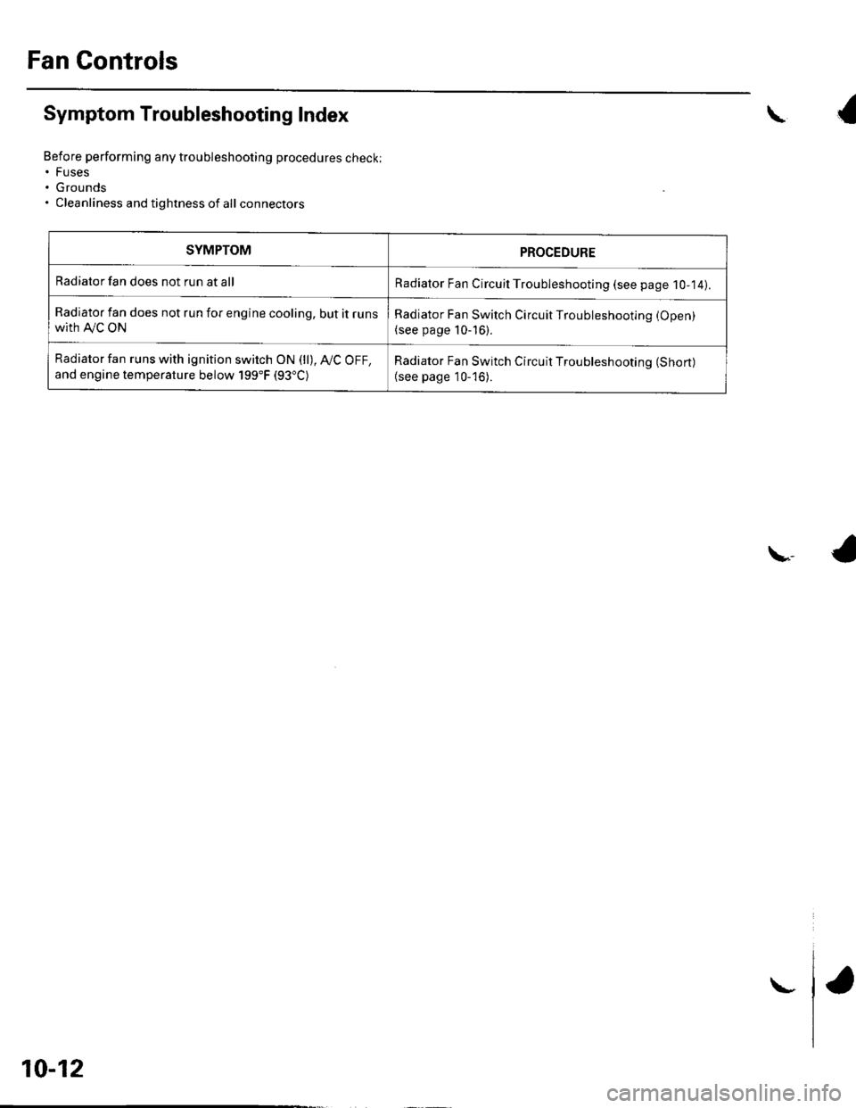
Fan Controls
Symptom Troubleshooting Index
Before performing any troubleshooting procedures check:. Fuses. Grounds. Cleanliness and tightness of all connectors
\{
\,4
SYMPTOMPROCEDURE
Radiator fan does not run at allRadiator Fan Circuil Troubleshooting (see page 1O-14).
Radiator fan does not run for engine cooling, but it runswith A,/C ON
Radiator Fan Switch Circuit Troubleshooting (Open)
(see page 10-16).
Radiator fan runs with ignition switch ON (ll), Ay'C OFF,
and engine temperature below 199"F (93"C)Radiator Fan Switch Circuit Troubleshooting (Short)
(see page 10-'16).
10-12
\-
Page 204 of 1139
Fan Gontrols
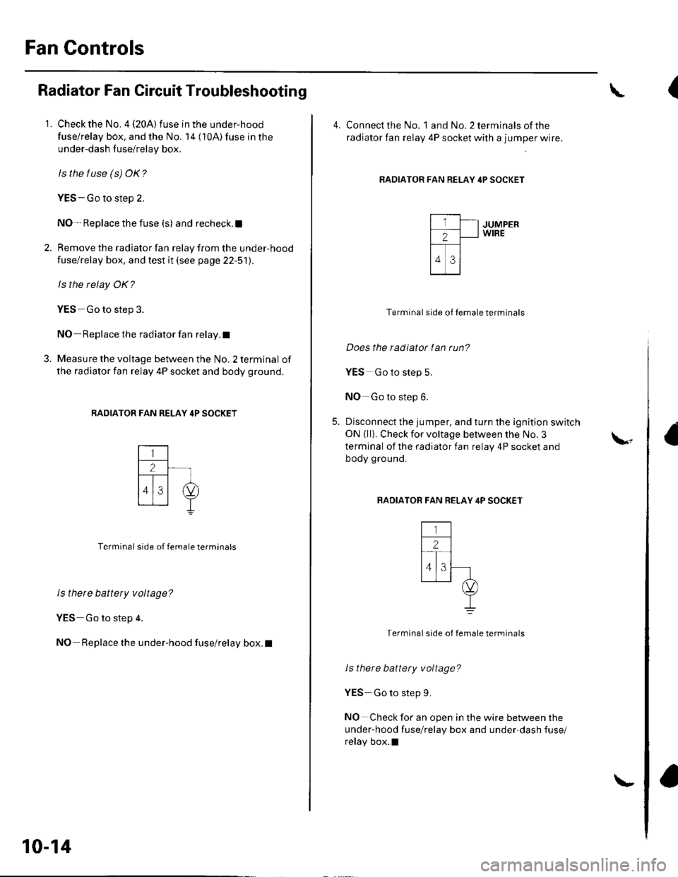
Radiator Fan Circuit Troubleshooting
1. Check the No. 4 (20A) fuse in the under-hood
fuse/relay box, and the No. 14 (10A) fuse in the
under-dash fuse/relay box.
ls the tuse (s) OK?
YES-Go to step 2.
NO- Replace the fuse (s) and recheck.l
2. Remove the radiator fan relay from the under-hood
fuse/relay box, and test it (see page 22-51).
ls the relay OK?
YES Go to step 3.
NO Replace the radiator fan relay. t
3. Measure the voltage between the No. 2 terminal of
the radiator fan relay 4P socket and body ground.
RADIATOR FAN RELAY 4P SOCKET
Terminal side of female terminals
ls there battery voltage?
YES Go to step 4.
NO Replace the under-hood fuse/relay box. I
10-14
\-
(
4. Connect the No. landNo.2terminalsofthe
radiator fan relay 4P socket with a jumper wire.
RADIATOR FAN RELAY 4P SOCKET
JUMPERWIRE
Terminal side of Iemale terminals
Does the radiatot fan run?
YES Go to step 5.
NO Go to step 6.
Disconnect the jumper, and turn the ignition switch
ON { ll}. Check for voltage between the No. 3
terminal of the radiator fan relay 4P socket and
body ground.
BADIATOB FAN RELAY 4P SOCKET
Termlnal side of female terminals
ls there battety voltage?
YES-Go to step 9.
NO Check for an open in the wire between the
under-hood fuse/relay box and under-dash fuse/
relay box.l
\-
Page 206 of 1139
Fan Controls
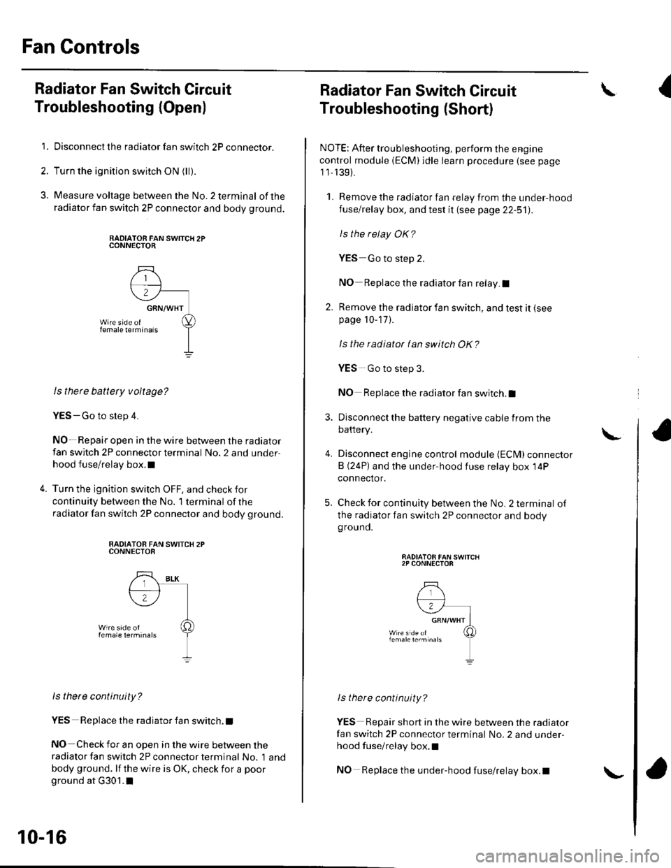
Radiator Fan Switch Circuit
Troubleshooting (Openl
1. Disconnect the radiator fan switch 2P connector.
2. Turn the ignition switch ON (ll).
3. Measure voltage between the No.2 terminal ofthe
radiator fan switch 2P connector and body ground.
RADIATOR FAN SWITCH 2PCONNECTOR
ls there battety voltage?
YES-Go to step 4.
NO- Repair open in the wire between the radiator
fan switch 2P connector terminal No. 2 and under-
hood fuse/relay box.l
Turn the ignition switch OFF, and check for
continuity between the No. '1 terminal of the
radiator fan switch 2P connector and body ground.
RADIATOB FAN SWITCX 2PCONNECTOR
ls there continuity?
YES Replace the radiator fan switch. t
NO Check for an open in the wire between theradiator fan switch 2P connector terminal No. 1 and
body ground. lf the wire is OK, check for a poor
ground at G301.1
10-16
\-
Radiator Fan Switch Circuit
Troubleshooting (Short)
NOTE: After troubleshooting, perform the engine
control module (ECM)idle learn procedure (see page
1 1,139).
1. Remove the radiator fan relay from the under-hood
fuse/relay box, and test it (see page 22-51).
ls the relay OK?
YES Go to step 2.
NO Replace the radiator fan relay.I
2. Remove the radiator fan switch, and test it (see
page 10-17 ).
Is the radiatot tan switch OK?
4.
YES Go to step 3.
NO Replace the radiator fan switch.I
Disconnect the battery negative cable from the
battery.
Disconnect engine control module {ECM) connector
B (24P) and the under hood fuse relay box 14P
connector.
Check for continuity between the No. 2 terminal of
the radiator fan switch 2P connector and bodygrouno.
RADIATOR FAN SWITCH2P CONNECTOR
lstnere continuity?
YES Repair short in the wire between the radiator
fan switch 2P connector terminal No. 2 and under-
hood fuse/relay box.l
NO Replace the under-hood fuse/relay box.t
\I
\