mirror HONDA CIVIC 2002 7.G User Guide
[x] Cancel search | Manufacturer: HONDA, Model Year: 2002, Model line: CIVIC, Model: HONDA CIVIC 2002 7.GPages: 1139, PDF Size: 28.19 MB
Page 857 of 1139
Connectors and Harnesses
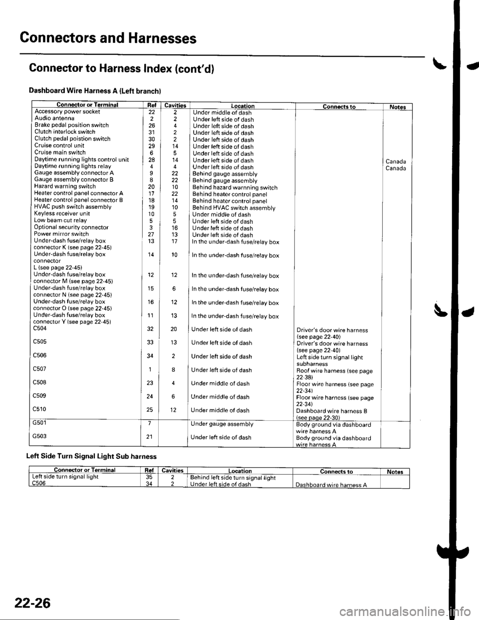
Dashboard Wire Harness A {Left branchl
Connector or TerminalffiAccessory power socketAudio antennaBrake pedal position switchClutch interlock switchClutch pedal poistion switchCruise control unitCruise main switchDaytime r!nning lights control unitDaytime running lights relayGauge assembly connector AGauge assembly connector BHazard warning switchHeater control panel connector AHeater control panel connector BHVAC push switch assemblyKeyless receiver unitLow beam cut relayOptional security connectorPower mirror switchUnder-dash fuse/relay boxconnector K (see page 22-45)Under'dash fuse/relay box
L {see page 22-45}Underdash fuse/relay boxconnector M lsee page 22'45)Under-dash fuse/relay boxconnector N (see page 22-45)UndeFdash fuse/relay boxconnector O (see page 22-45)UndeFdash fuse/relay boxconnectorY (see page 22 45)c504
c505
c506
c507
c508
c509
c510
22226
3029628
I820111819105327
,I4
12
11
34
1
24
25
2 Under middle of dash2 Under left side of dash4 ] Under left side of dash2 ] Under left srde of dash2 | Under left side of dash14 I Under left side of dash5 Under left side of dash14 Under lett side of dash4 Under lett side of dash22 I Behind gauge assembly22 i Behind gauge assembly10 Behind hazard warnning switch22 Behind heater control panel'14 Behind heater control panel10 ] Behind HVAC switch assembly5 I Under middle of dash5 lUnderleftsideofdash16 Under lefr side of dash13 Under left side oI dash17 ln the under-dash fuse/relay box
CanadaCanada
l0In the under-dash fuse/relay box
In the undeFdash fuse/relay box
In the underdash fuse/relay box
In the under-dash fuse/relay box
In the under-dash fuse/relay box
Under left side of dash
Under left side ot dash
Under left side of dash
Under left side of dash
Under middle of dash
Under middle of dash
Under middle ol dash
Driver's door wire harness(see page 22'40)Driver's door wire harness(see page 22-40)Left side turo signal lightsuonarnessRoof wire harness (see page22 3AlFloor wire harness {see page22-341Floor wire harness (see page22 34JDashboard wire harness B(see oaoe 22-30)
12
12
G501
G503
1
21
Under gauge assembly
Under left side of dash
Body ground via dashboard
Body ground via dashboard
Left Side Turn Signal Light Sub harness
Connector to Harness Index (cont'd)
L
Connector or TerminalCavitiesLocationConnects toNolesLeft side turn signal lightc506353422Behind left side turn signal lightUnder left side of dashDashboard wire harness A
22-26
Page 871 of 1139
Connectors and Harnesses
\,Connector to Harness lndex (cont'd)
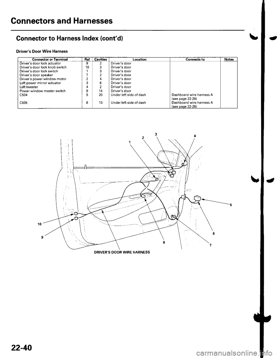
Driver's Door Wire Harness
Connector or TerminalReICavitiesLocationConnectstoNotesDriver's door lock actuatorDriver's door lock knob switchDriver's door lock switchDriver's door speakerDriver's power window motorLeft power mirror actuatorLeft tlveeterPower window master switchc504
c505
9101723
85
6
2332
62
20
't3
Driver's doorDriver's doorDriver's doorDriver's dooaDriver's doorDriver's doorDriver's doorDriver's doorUnder left side of dash
Under left side of dash
Dashboard wire harness A\see page 22-261Dashboard wire harness A
DRIVER'S OOOR WIRE HABNESS
22-40
Page 872 of 1139
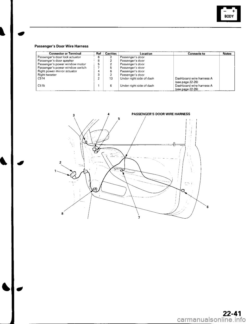
Passenger's Door Wire Harness
Connector or TerminalRelCavitiesLocationConnectstoNotesPassenger's door lock actuatorPassenger's door speakerPassenger's power window motorPassenger's power window switchRight power mirror actuatorRighttweeterc514
6I51432
1
22256213
6
Passenger's doorPassenger's doorPassenger's doorPassenger's doorPassenger's doorPassenger's doorUnder right side of dash
Under right side of dash
Dashboard wire harness A(see page 22'26)Dashboard wire harness Alsee oeoe 22-26\
PASSENGER'S DOOR WIRE HABNESS
22-41
Page 878 of 1139
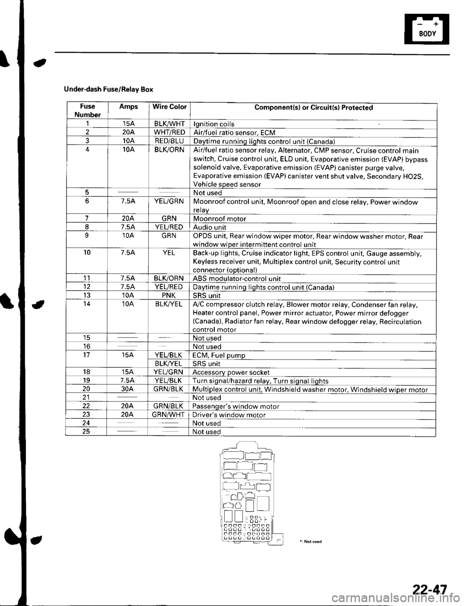
Under-dash Fuse/Relay Box
Fuse
Number
AmpsWire ColorComponent(s) or Circuit(s) Protected
115ABLKA/VHTlgnition coils
2204WHT/REDAirlfuel ratio sensor, ECM
310ARED/BLUDaytime running Iights control unit {Canada)10ABLI(ORNAir/fuel ratio sensor relay, Alternator, CMP sensor, Cruise control main
switch, Cruise control unit. ELD unit, Evaporative emission (EVAP) bypass
solenoid valve, Evaporative emission (EVAP)canister purge valve,
Evaporative emission (EVAP) canister vent shut valve, Secondary H02S,
Vehicle speed sensor
5Not used
67.5AYEUGRNMoonroof control unit, Moonroof open and close relay, Power window
relaV
7204GRNMoonroof motor
I7.5AYEUREDAudio unit
910AGRNOPDS unit, Rear window wiper motor, Rear window washer motor, Rear
window wiper intermittent control unit
107.54YELBack-up lights, Cruise indicator light, EPS control unit, Gauge assembly,
Keyless receiver unit, Multiplex control unit, Security control unit
connector (optional)
117.5ABLIVORNABS modulator-control unit
127.5AYEUREDDaytime runnino liohts control unit (Canada)
1310APNKSRS unit't410ABLK/YE LA,,/C compressor clutch relay, Blower motor relay, Condenser fan relay,
Heater control panel, Power mirror actuator, Power mirror defogger(Canada), Radiator fan relay, Rear window defogger relay, Recirculation
control motor1ENot used
loNot used
1715AYE L/B LKECM, Fuel pump
B LK/YE L>H> Unrr
1815AYEUGRNAccessory power socket
197.5AYEUBLKTurn siqnal/hazard relav, Turn siqnal liohts
2030AGRN/BLKMultiplex control unit, Windshield washer motor. Windshield wioer motor21Not used
22204GRN/BLKPassenqer's window motor
2320A.G R N,A/VHTDriver's window motor
24Not used
25Not used
__^:Hr tl_l
f at-t
at I
r^,rl fl
!!;r -
!339,i;s!!sf Fnf : |rnITf
22-47
Page 879 of 1139
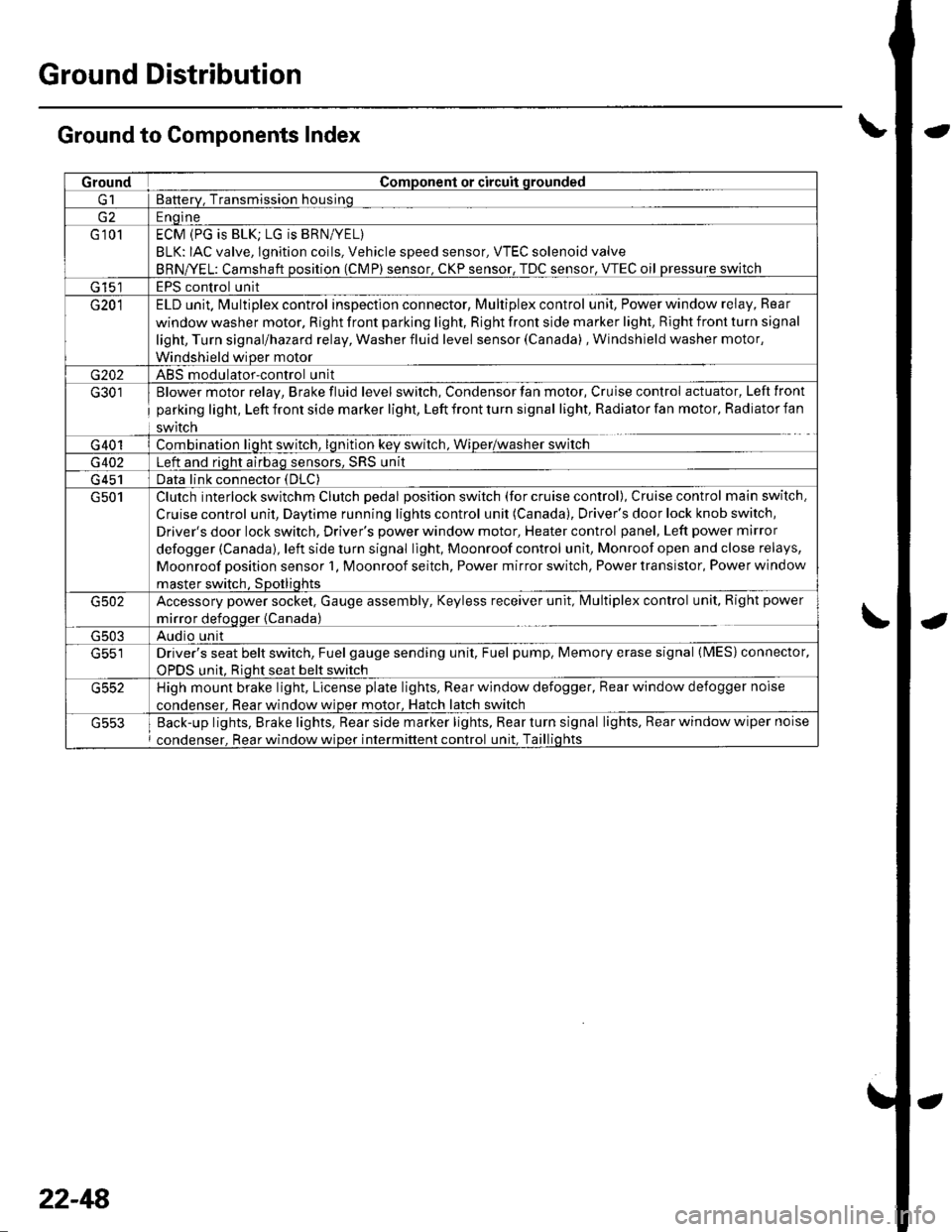
Ground Distribution
Ground to Components Index
GroundComponent or circuit qrounded
Batterv, Transmission housinq
E ngine
G 101ECM (PG is BLK; LG is BRN/YEL)
BLK: IAC valve, lgnition coils, Vehicle speed sensor, VTEC solenoid valve
BRNA/EL: Camshaft oosition (CMP) sensor. CKP sensor, TDC sensor. VTEC oil pressure switch
G 15'�]EPS control unit
G201ELD unit. Multiplex control inspection connector, Multiplex control unit, Power window relay, Rear
window washer motor, Right front parking light, Right front side marker light, Right front turn signal
light, Turn signal/hazard relay, Washer fluid level sensor (Canada) , Windshield washer motor,
Windshield wiDer motor
G202ABS modulator-control unit
G301
G401
Blower motor relay, Brake fluid level switch, Condensor fan motor, Cruise control actuator, Left front
parking light, Left front side marker light, Left front turn signal light, Radiator fan motor, Radiator fan
swrtcn
Combination liqht switch, lqnitlon kev srvitch, Wiper/wasfrer sr,virch
G402Left and riqht airbaq sensors, SRS unit
G 451Data link connector (DLC)
G501Clutch interlock switchm Clutch pedal position switch (for cruise control), Cruise control main switch,
Cruise control unit, Daytime running lights control unit (Canada), Driver's door lock knob switch,
Driver's door lock switch, Driver's power window motor, Heater control panel, Left power mirror
defogger (Canada), left side turn signal light, Moonroof control unit, Monroof open and close relays,
Moonroof position sensor '1, Moonroof seitch, Power mirror switch, Power transistor, Power window
master switch. SDotliqhts
G502Accessory power socket, Gauge assembly, Keyless receiver unit, lvlultiplex control unit, Right power
mirror defogger {Canada)
G503Audio unit
G551Driver's seat belt switch, Fuel gauge sending unit, Fuel pump, Memory erase signal (IMES) connector,
OPDS unit. Rioht seat belt switch
G552High mount brake light, License plate lights, Rear window defogger, Rear window defogger noise
condenser. Rear window wioer motor, Hatch latch switch
Back-up lights, Brake lights, Rear side marker lights, Rear turn signal lights, Rear window wiper noise
condenser, Rear window wiper intermittent control unit, Taillights
22-48
Page 933 of 1139
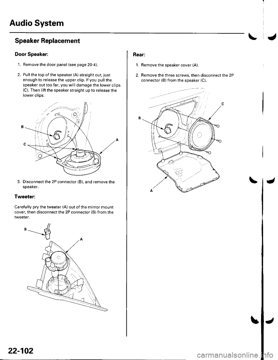
Audio System
Speaker Replacement
Door Speaker:
1. Remove the door panel (seepage20-4).
2. Pull the top of the speaker {A) straight out, just
enough to release the upper clip. lf you pull the
speaker out too far, you will damage the lower clips(C). Then lifi the speaker straight up to release the
lower clips.
3. Disconnect the 2P connector (B), and remove the
speaKer.
Tweeter:
Carefully pry the tweeter (A) out of the mirror mount
cover, then disconnect the 2P connector (B) from the
tweeter.
'-----d
22-102
Rear:
1.Remove the speaker cover (A).
Remove the three screws, then disconnect the 2P
connector (B) from the speaker (C).
2.
Page 945 of 1139
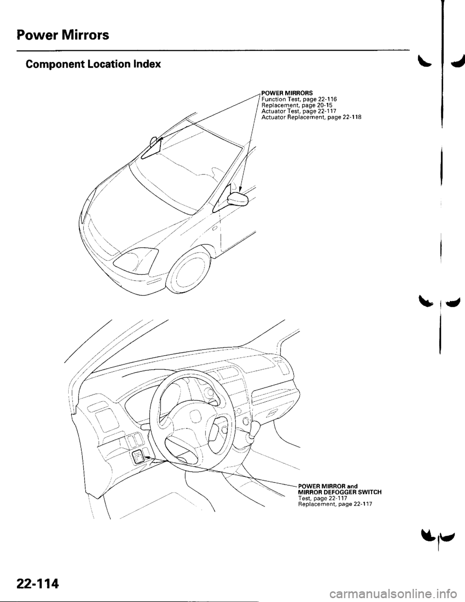
Power Mirrors
Component Location Index
POWER MIRRORSFunction Test, page 22-116Replacement, page 20-15Actuator Test, page 22-117Actuator Replacemenl, page 22-1 18
POWER MIRROR andMIRROR DEFOGGER SWITCHlesl, page 22-111Replacement, page 22-1 17
---\,--,-'/ -:,)
j-' ',i. it .i/q3:.[
' \, -,''
-lo' '
-o
t:
,.'7
22-114
$r-
Page 947 of 1139
Power Mirrors
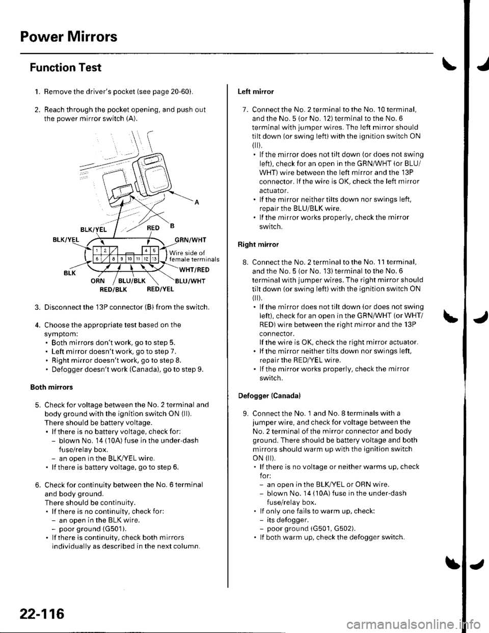
Function Test
1. Remove the driver's pocket (see page 20-60).
2. Reach through the pocket opening, and push out
the power mirror switch (A).
,\
RED B
Wire side oftemale terminals
WHT/RED
RED/YEL
3. Disconnectthe'13P connector (B) from the switch.
4. Choose the appropriate test based on the
symptom:. Both mirrors don't work, go to step 5.. Left mirror doesn't work, go to step 7.. Right mirror doesn't work, go to step 8.. Defogger doesn't work (Canada), go to step 9.
Both mirrors
5. Check for voltage between the No. 2 terminal and
body ground with the ignitlon switch ON (ll).
There should be battery voltage.. lf there is no battery voltage, check for:- blown No. 14 (10A) fuse in the under'dash
fuse/relay box.- an open in the BLKryEL wire.. lf there is battery voltage, goto step 6.
6. Check for continuity between the No. 6 terminal
and body ground.
There should be continuity.. lf there is no continuity, check for:- an open in the BLK wire.- poor ground (G501).
. lf there is continuity, check both mirrors
individually as described in the next column.
RED/BLK
22-116
Left mirror
7. Connect the No. 2 terminal totheNo. l0terminal,
and the No. 5 (or No. 12) terminal to the No. 6
terminal with jumper wires. The left mirror should
tilt down (or swing left)with the ignition switch ON
fl r).. lf the mirrordoes nottiltdown (ordoes notswing
left), check for an open in the GRN/WHT (or BLU/
Wl-lT)wire between the left mirror and the 13P
conneclor, lf the wire is OK, check the left m irror
actualor.. lf the mirror neithertilts down nor swings left.
repair the BLU/BLK wire.. lf the mirrorworks properly, checkthe mirror
SWIICN,
Right mirror
8. Connect the No. 2 terminalto the No. 11 terminal,
and the No. 5 {or No. 13) terminal to the No. 6
terminal with jumper wires. The right mirror should
tilt down (or swing left)with the ignition switch ON
(
).. lf the mirror does not tilt down (or does not swing
left), check for an open in the GRN/WHT (or WHT/
RED)wire between the right mirror and the 13P
connector.
lf the wire is OK, check the right mirror actuator.. lf the mirrorneithertiltsdown norswings left,
repalr the RED|YEL wire.' lf the mirrorworks properly. checkthe mirror
swrrcn.
Defogger (Canada)
9. Connect the No. 1 and No. I terminals with a
jumper wire, and check for voltage between the
No. 2 terminal of the mirror connector and body
ground. There should be battery voltage and both
mirrors should warm up with the ignition switch
oN
t).. lf there is novoltage orneitherwarms up, check
for:- an open in the BLKI/EL or oRN wire.- blown No. 14 ('l0A)fuse in the under-dash
fuse/relay box.. lf only one fails to warm up, check:- its defogger.- poor ground (G501, G502). lf both warm up, checkthedefoggerswitch.
Page 948 of 1139
1.
2.
3.
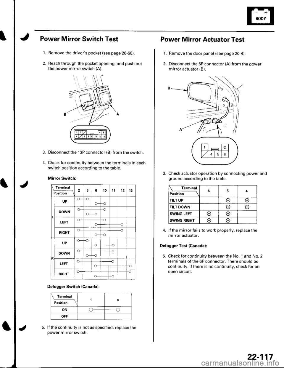
Power Mirror Switch Test
Remove the driver's pocket (see page 20-60).
Reach through the pocket opening, and push out
the power mirror switch (A).
Disconnect the 13P connector (B) f rom the switch.
Check for continuity between the terminals in each
switch position according to the table.
Mirror Switch:
\.f9.-'"1L
Position256 1011 1213
UPCF--o
o-o
o-
G-c)o
o-o-
-o
!
RIGHT-o
o-o
UP
"[T
RIGHT
Defogger Switch (Canadal:
Te.minal
il;;; tlfI8
ONoo
OFF
lf the continuity is not as specified, replace thepower mirror switch.
5.
22-117
1,
2.
Power Mirror Actuator Test
Remove the door panel (see page 20-4).
Disconnect the 6P connector (A) from the power
mirror actuator (B).
Check actuator operation by connecting power and
ground according to the table.
Terminal
Position64
TILT UPoo
TILT DOWNo
SWING LEFTo@
SWING RIGHT@
4. lf the mirror fails to work properly, replace the
mtrror actuator.
Defogger Test {Canada);
5. Check for continuity between the No. 1and No.2
terminals of the 6P connector. There should be
continuity. lf there is no continuity, check for an
open circuit.
Page 949 of 1139
Power Mirrors
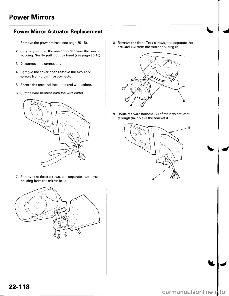
Power Mirror Actuator Replacement
Remove the power mirror (see page 20-15).
Carefully remove the mirror holder from the mirror
housing. Gently pull it out by hand (see page 20-15).
Disconnect the connector.
Remove the cover, then remove the two Torx
screws from the mirror connector.
Record the terminal locations and wire colors.
Cut the wire harness with the wire cutter.
7. Remove the three screws, and separate the mirror
housinq from the mirror base.
'1.
2.
3.
4.
5.
6.
22-118
J
\4
8. Remove the three Torx screws, and separate lhe
actuator (A) from the mirror housing {B).
Route the wire harness {A) ofthe new actuator
through the hole in the bracket (B).9.
\J