relat HONDA CIVIC 2002 7.G User Guide
[x] Cancel search | Manufacturer: HONDA, Model Year: 2002, Model line: CIVIC, Model: HONDA CIVIC 2002 7.GPages: 1139, PDF Size: 28.19 MB
Page 713 of 1139
Dashboard
Instrument Panel Removal/
Installation
NOTE:. When prying with a flat-tip screwdriver, wrap it withprotective tape, and apply protective tape around the
related parts, to prevent damage.. Take care not to scratch the dashboard and related
pa rts.
1. Tilt the steering column down.
2. Remove the steering column upper cover {see page
17,9).
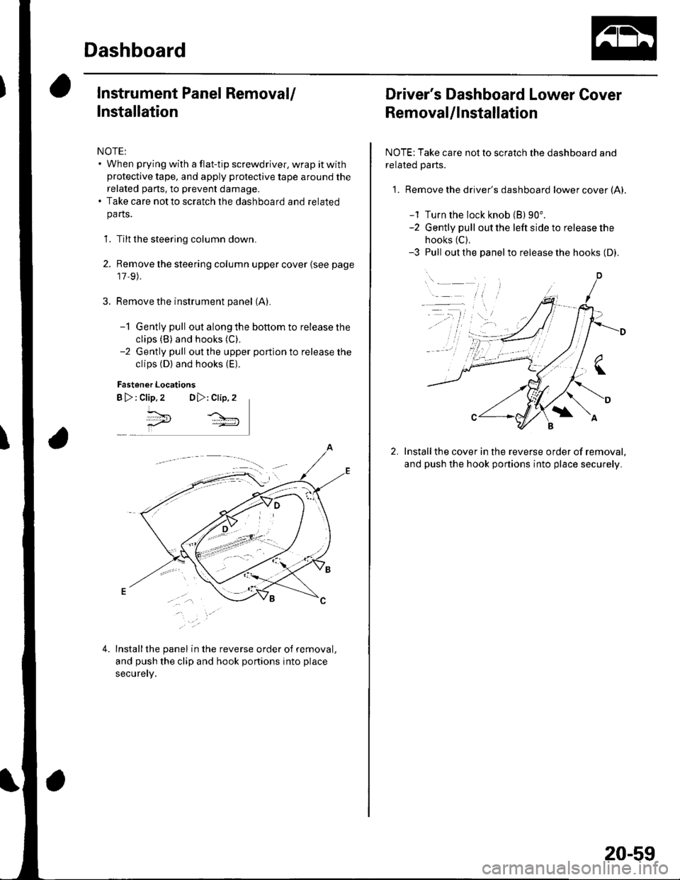
Remove the instrument panel (A).
-1 Gently pull out along the bottom to release the
clips (B) and hooks (C).
-2 Gently pull out the upper portion to release the
clips (D) and hooks (E).
Fastener Locations
B >: clip.2 DD,: Clip,2
^*,
4.Installthe panel in the reverse order of removal,
and push the clip and hook portions into place
securery.
Driver's Dashboard Lower Cover
Removal/lnstallation
NOTE: Take care not to scratch the dashboard and
related Parts.
1. Remove the driver's dashboard lower cover (A).
-1 Turn the lock knob (B) 90".-2 Gently pull out the left side to release the
hooks (C),
-3 Pull out the panelto release the hooks (D).
Installthe cover in the reverse order of removal,
and push the hook portions into place securely.
20-59
Page 714 of 1139
Dashboard
Driver's Dashboard Under Cover
Removal/lnstallation
NOTE: Take care not to scratch the dashboard and
related parts.
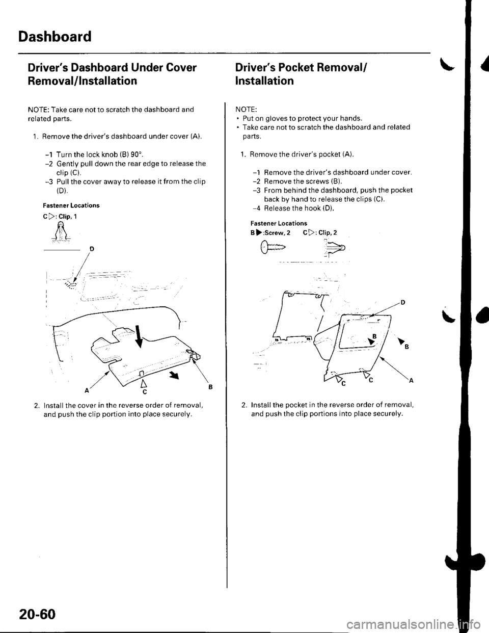
1 . Remove the driver's dashboard under cover (A).
-1 Turn the lock knob (B) 90'.-2 Gently pull down the rear edge to release the
clip (C).
-3 Pull the cover away to release it from the clip
{D).
Fastener Locations
C >: Clip. 1
n
Installthe cover in the reverse order of removal,
and push the clip portion into place securely.
)
20-60
Driver's Pocket Removal/
lnstallation
NOTE:. Put on gloves to protect your hands.. Take care not to scratch the dashboard and related
pa ns.
1. Remove the driver's pocket (A)
-1 Remove the driver's dashboard under cover.-2 Remove the screws (B).
-3 From behind the dashboard, push the pocket
back by hand to release the clips (C).
4 Release the hook (D).
Fastener Locations
B ):Screw,2 C>: Clip,2
Installthe pocket in the reverse order of removal,
and push the clip portions into place securely.
','"\5;;t='
\
2.
Page 715 of 1139
Shift Lever Trim Removal/lnstallation
NOTE:. Take care not to scratch the dashboard and related
pa rts.. Put on gloves to protect your hands.
1. Remove the glove box (see page 20-63).
2. Remove the shift knob.
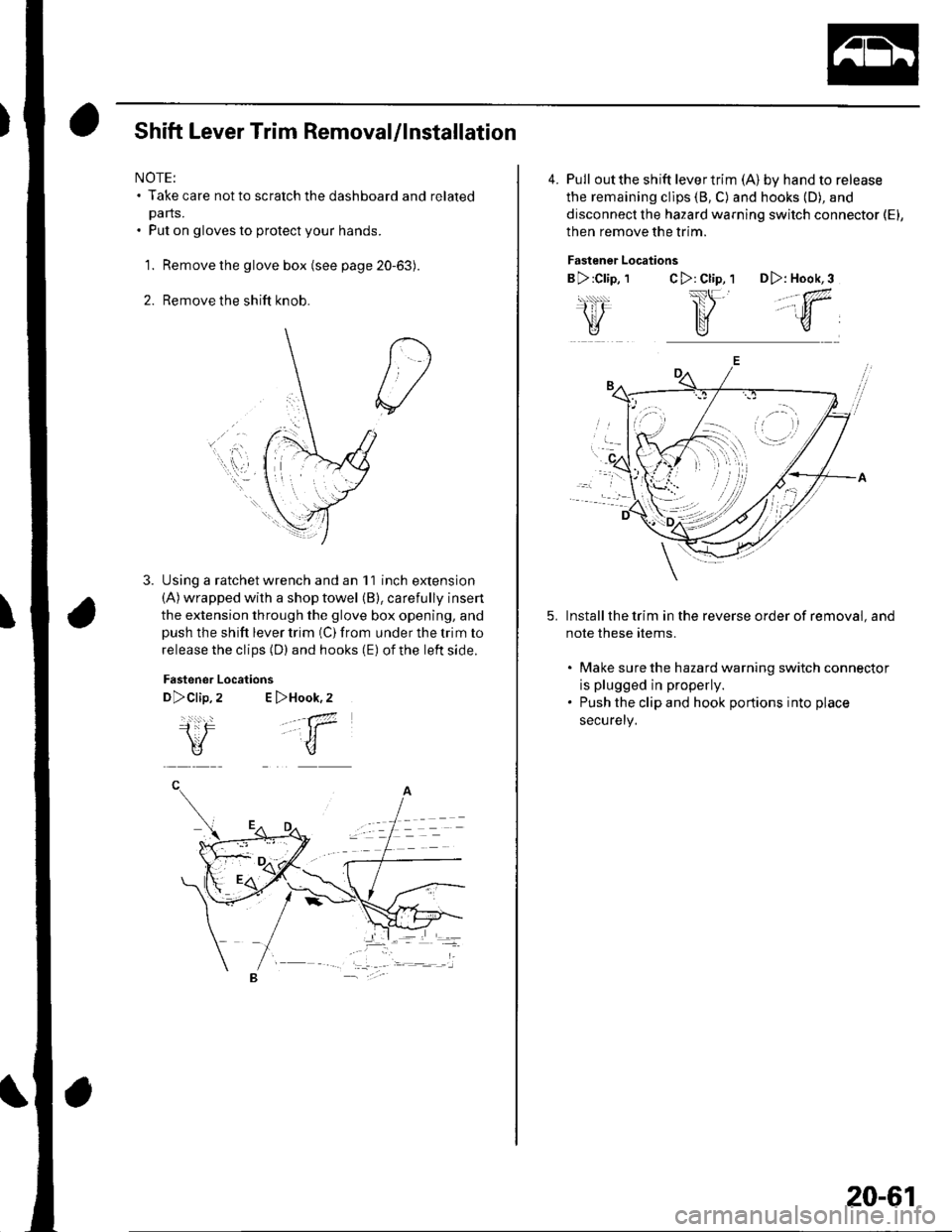
Using a ratchet wrench and an 11 inch extension(A) wrapped with a shop towel (B), carefully insert
the extension through the glove box opening, andpush the shift lever trim (C) from under the trim to
release the clips (D) and hooks (E) of the left side.
Fastener
D>clip,
i:F\V
Locations
2 E >Hook,2
.-a7
-t1
u
4. Pull outthe shift levertrim (A) by hand to release
the remaining cllps (8, C) and hooks (D), and
disconnect the hazard warning switch connector (El,
then remove the trim.
Fastener Locations
B >:Clip, 1C>: Cl;p, 1 D>: Hook,3
,,.;w,
Install the trim in the reverse order of removal, and
note these rtems.
. Make sure the hazard warning switch connectot
is plugged in properly.. Push the clip and hook portions into place
securely,
-
,,
20-61
Page 716 of 1139
Dashboard
Dashboard Center Panel Removal/lnstallation
NOTE:. Put on gloves to protect your hands.. When prying with a flat-tip screwdriver, wrap it with
protective tape, and apply protective tape around the
related parts, to prevent damage.. Take care not to scratch the dashboard and related
parts.
1. Make sure you have the anti-theft code for the radio,
the write down the frequencies for the preset
buttons.
Remove these items:
. Driver's dashboard lower cover (see page 20-59)
. Passenger's dashboard lower cover (see page
20-63).. Glove box (see page 20-63).. Shift lever trim {see page 20-61).
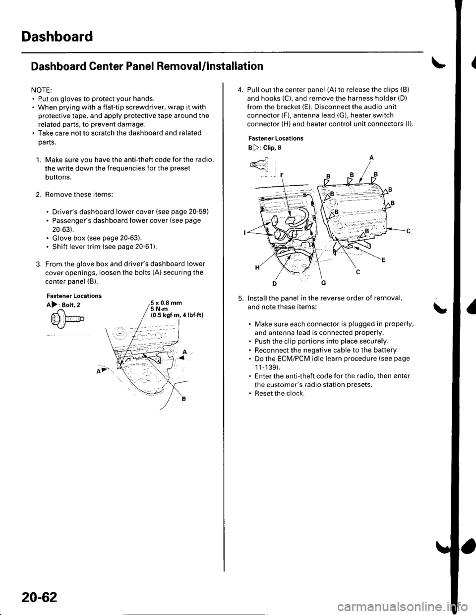
From the glove box and driver's dashboard Iower
cover openings, loosen the bolts (A) securing the
center panel (B).
2.
Fastener Locations
A): Bolt, 2x 0.8 mm5Nm
;.'
20-62
4. Pull out the center panel (A) to release the clips (B)
and hooks (C), and remove the harness holder (D)
from the bracket (E). Disconnect the audio unit
connector (F), antenna lead (G), heater switch
connector (H) and heater control unit connectors (l).
Fastener Locations
B ): Clip, 8
Installthe panel in the reverse order of removal,
and note these items:
Make sure each connector is plugged in properly,
and antenna lead is connected properly.
Push the clip portions into place securely.
Reconnect the negative cable to the battery.
Do the ECN4/PCt\4 idle learn procedure {see page
1l-139).
Enter the anti-theft code for the radio. then enter
the customer's radio station presets.
Reset the clock.
*4
,F
\
Page 717 of 1139
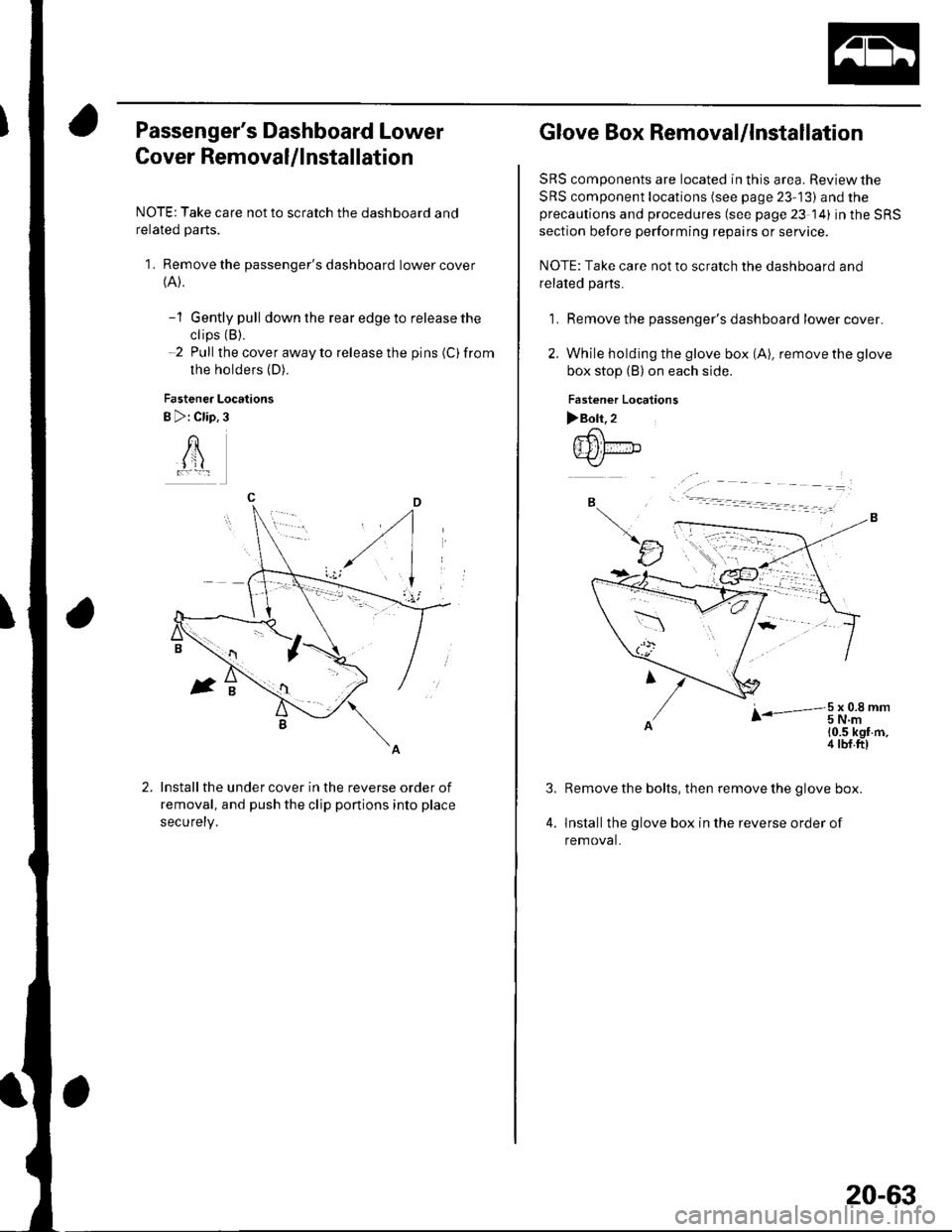
Passenger's Dashboard Lower
Cover Removal/lnstallation
NOTE: Take care not to scratch the dashboard and
related parts.
1. Remove the passenger's dashboard lower cover(A).
-1 Gently pull down the rear edge to release the
ctips (B).
-2 Pull the cover away to release the pins (C)from
the holders (D).
Fastener Locations
B >: Clip,3
AI jl
Install the under cover in the reverse order of
removal, and push the clip ponions into place
securety.
Glove Box Removal/lnstallation
SRS components are located in this area. Review the
SRS component locations (see page 23-13) and theprecautions and procedures (see page 23 14) in the SRS
section before performing repairs or service.
NOTE: Take care not to scratch the dashboard and
related pa rts.
1. Remove the passenger's dashboard lower cover.
2. While holding the glove box (A), remove the glove
box stop (B) on each side.
Fastener Localions
>Boh.2.-6\
{Ill fir-"b.-<,/
B
tJ
r-3t.oi,t-'
10.5 kgf m,4 tbf.ft)
4.
Remove the bolts, then remove the glove box.
lnstallthe glove box in the reverse order of
removal.
20-63
Page 720 of 1139
Dashboard
Dashboard Removal/lnstallation
SRS components are located in this area. Review the
SRS component locations (see page 23-13) and the
precautions and procedures (see page 23-14) in the SRS
section before performing repairs or service.
NOTE:. When prying with a flat-tip screwdriver, wrap it with
protective tape, and apply protective tape around the
related parts to prevent damage.. Have an assistant help you when removing and
installing the dashboa rd.. Take care not to scratch the dashboard, body, and
other related parts.
. Put on gloves to protect your hands.
1. Make sure you have the anti-theft code for the radio,
then write down the frequencies for the preset
buttons.
Disconnect the negative cable from the battery, and
wait at least three minutes before beginning work.
Remove these items:
. Driver's dashboard lower cover (see page 20-59). Driver's dashboard under cover (see page 20-60). Passenger's dashboard lower cover (see page
20-63). Glove box (see page 20-63). Consoles, front and rear (see page 20-57). Shift lever trim {see page 20-61). Center panel (see page 20-62). Kick panels, both sides (see page 20-50). A-pillar trim. both sides (see page 20-50). Steering column (see page 17-9)
20-66
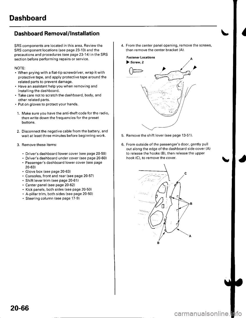
4. From the center panel opening, remove the screws,
then remove the center bracket (A).
Fastener Locations
):Screw,2
Remove the sh ift lever (see page 13-51).
From outside of the passenger's door, gently pull
out along the edge of the dashboard side cover (A)
to release the hooks (B), then release the upper
hook (C), to remove the cover.
Page 750 of 1139
Exterior Trim
A-Pillar Corner Trim Replacement
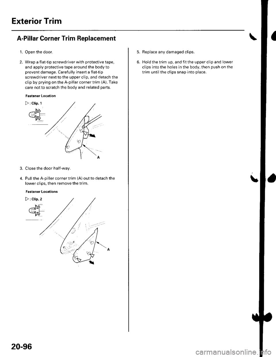
1.Open the door.
Wrap a flat-tip screwdriver with protective tape,
and apply protective tape around lhe body to
prevent damage. Carefully insert a flat-tip
screwdriver next to the upper clip, and detach the
clip by prying on the A-pillar corner trim (A). Take
care not to scratch the body and related parts.
Fastener Location
Close the door half-way.
Pull the A-piller corner trim (A) out to detach the
lower clips, then remove the trim.
Fastener Locations
3.
20-96
5.Replace any damaged clips.
Hold the trim up, and fit the upper clip and lower
clips into the holes in the body, then push on the
trim until the clips snap into piace.
\
Page 760 of 1139
Openers
Hood Opener Cable Replacement
NOTE:. Put on gloves to protect your hands.. Take care not to scratch the body and related parts.
l. Remove these items:
. Front bumper (see page 20-85). Front inner fender, leftside(seepage20-102). Kick panel, left side (see page 20-50)
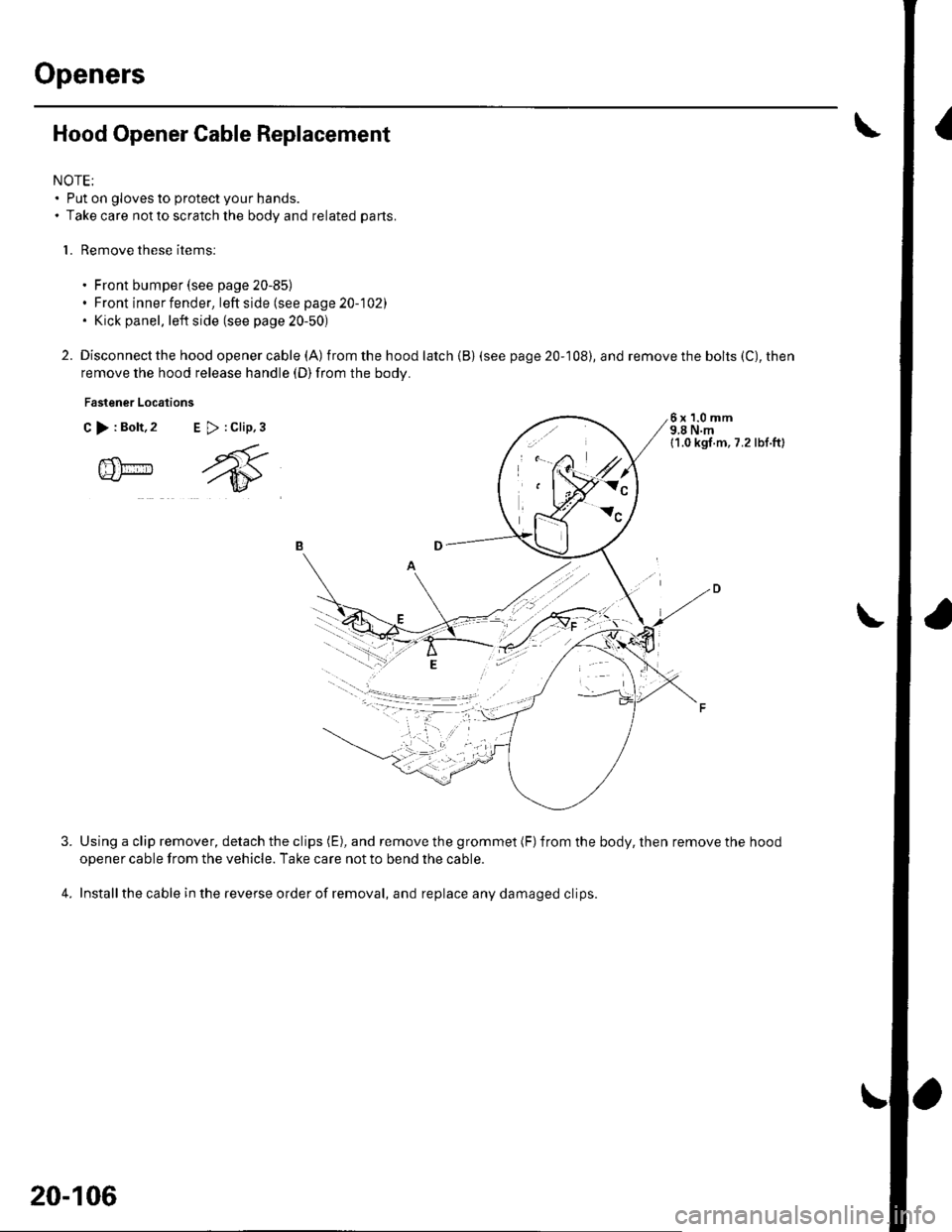
2. Disconnect the hood openercable (A) from the hood latch {B) (see
remove the hood release handle (D)from the body.
Fastener Locations
C >:Bolt,2 E >:Clip,3
page 20-108), and remove the bolts (C), then
6x1.0mm9,8 N.m11.0 kgl.m, 7.2 lbl.ft)
@m
4.
Using a clip remover, detach the clips (E), and remove the grommet (F)from the body, then remove the hood
opener cable from the vehicle. Take care not to bend the cable.
Installthe cable in the reverse order of removal, and replace any damaged clips.
l,.t'.
W:"
20-106
Page 761 of 1139
2.
5.
Fuel Fill Door Opener Cable Replacement
SRS components are located in this area. Review the SRS component locations (see page 23-13) and the precautions
and procedures (see page 23-14) in the SRS section before performing repairs or service.
NOTE;. Put on gloves to protect your hands.. Take care notto scratch the body and related parts.
1. Remove these items from the left side of the vehicle:
. Door silltrim {see page 20-50). Rear side trim panel (see page 20-51)
Pullthe carpet back as necessary (see page 20-55).
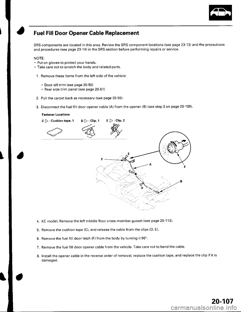
Disconnect the fuel fill door opener cable (A) from the opener (B) (see step 3 on page 20-109).
Fastener Locations
C >:Cushiontape, 1 D >: Clip, 1E > : Clip, 2
4. KCmodel: Removethe left middle floor cross-member gusset (see page 20-113).
5. Remove the cushion tape {C), and release the cable from the clips (D, E).
6. Removethefuel fill doorlatch (F)fromthe bodybyturning it90'.
7. Remove the fuel fill door opener cable from the vehicle. Take care not to bend the cable
8. Install theopenercableinthereverseorderofremoval,replacethecushiontape,andreplacetheclipifitis
oamageo.
20-107
Page 829 of 1139
Heating and Air Conditioning
A/C System Tests (cont'd)
1.
Performance Test
Air conditioning refrigerant or lubricant vapor
can irritate your eyes, nose, or throar.
Be carefulwhen connecting service equipment.
Do not breathe refrigerant or vapor.
The performance test will help determine if the air
conditioner system is operating within specifications.
Use only service equipment that is U.L.-listed and is
cenified to meet the requirements of SAE J2210 toremove HFC-134a (R-134alfrom the air conditioning
system.
lf accidental system discharge occurs, ventilate the
work area before resuming service
R-134a service equipment or vehicle air conditioning
systems should not be pressure tested or leak testedwith compressed air.
Additional health and safety information may be
obtained from the refrigerant and lubricant
manufacturers.
Connect a R-134a refrigerant recover/recycling/
charging station to the high-pressure service port
and the low-pressure service port, following the
equipment manufacturer's instructions.
Determine the relative humidity and air
Iemperaru re.
' Compressed air mixed with R-134a forms a
combustible vapor.. The vapor can burn or explode causing serious
Injury.. Never use compressed air to pressure test
R-134a service equipment or vehicle air
conditioning systems.
21-58
4.
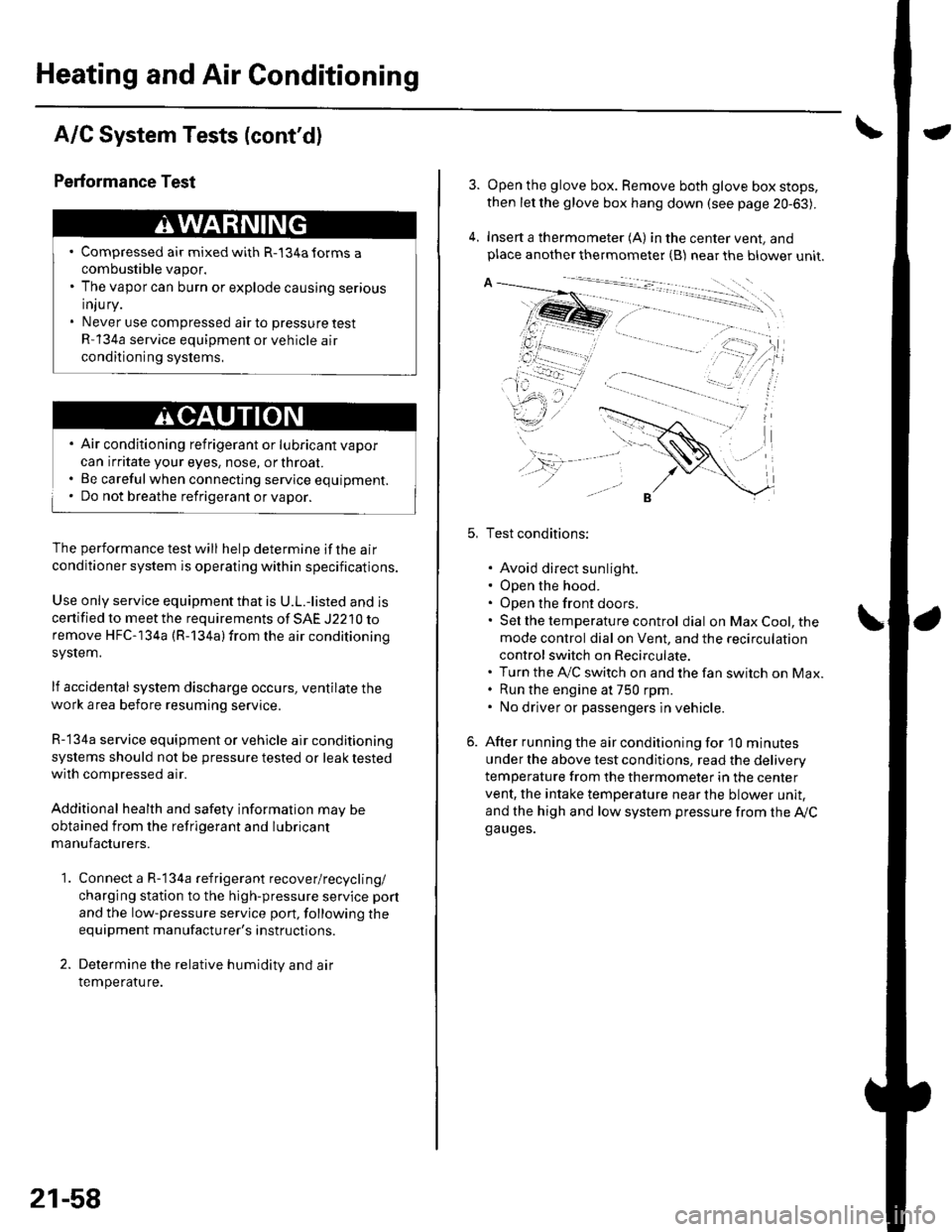
Open the glove box. Remove both glove box stops,
then let the glove box hang down (see page 20-63).
Insert a thermometer (A) in the center vent, andplace another thermometer {B) near the blower unit.
Test conditions:
. Avoid direct sunlight.. Open the hood.. Open the front doors.. Sel the temperature control dial on Max Cool, the
mode control dial on Vent, and the recirculation
control switch on Recirculate.. Turn the A,/C switch on and the fan switch on Max.. Run the engine at 750 rpm.. No driver or passengers in vehicle.
After running the air conditioning for I0 minutes
under the above test conditjons, read the delivery
temperature from the thermometer in the center
vent, the intake temperature near the blower unit,
and the high and low system pressure from the Ay'Cga uges.