wheel alignment HONDA CIVIC 2002 7.G User Guide
[x] Cancel search | Manufacturer: HONDA, Model Year: 2002, Model line: CIVIC, Model: HONDA CIVIC 2002 7.GPages: 1139, PDF Size: 28.19 MB
Page 565 of 1139
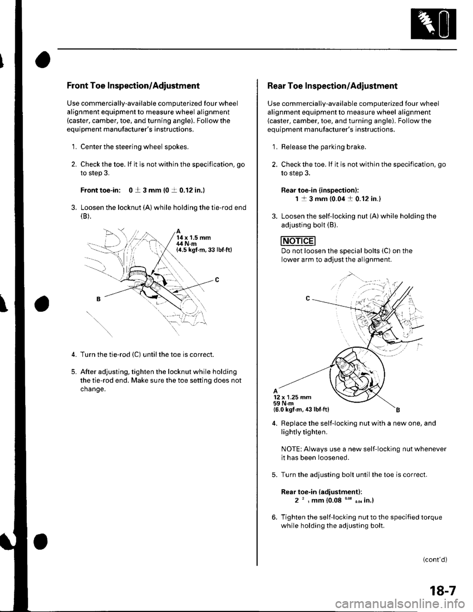
Front Toe Inspection/Adjustment
Use commercially-available computerized four wheel
alignment equipment to measure wheel alignment(caster, camber, toe, and turning angle). Follow the
equipment manufacturer's instructions,
1. Center the steering wheel spokes.
2. Checkthetoe. lf it is not with in the specif ication, go
to step 3.
Front toe-in: 0 t 3 mm {0 t 0.12 in.)
3. Loosen the locknut (A) while holding the tie-rod end(B ).
A14x 1.5 mm,14 N.m(a.5 kgt m,33 lbt.ftl
5.
Turn the tie-rod (C) untilthe toe is correct.
After adjusting, tighten the locknut while holding
the tie-rod end. Make sure the toe setting does not
change.
1,;
Rear Toe Inspection/Adiustment
Use commercially-available computerized four wheel
alignment equipment to measure wheel alignment(caster, camber, toe, and turning angle). Follow the
equipment manufacturer's instructions.
1, Release the parking brake.
2. Checkthe toe. lf it is not within the specification. go
to step 3.
Rear toe-in {inspection):
1 1 3 mm (0.04 a 0.12 in.)
3. Loosen the self-locking nut (A)while holding the
adjusting bolt (B).
Do not loosen lhe special bolts (C) on the
lower arm to adjust the alignment.
4. Replace the self-locking nut with a new one, and
lightly tighten.
NOTE: Always use a new self-locking nut whenever
it has been loosened.
Turn the adjusting bolt until the toe is correct.
Rear toe.in (adiustment):
2 ' , mm {0.08 "' ,. in.}
Tighten the self-locking nut to the specified torque
while holding the adjusting bolt.
(cont'd )
18-7
Page 566 of 1139
Front and Rear Suspension
Wheel Alignment (cont'dl
Turning Angle Inspection
Use commercially-available computerized four wheel
alignment equipment to measure wheel alignment(caster. camber, toe, and turning angle). Followthe
equiDment manufacturer's instructions.
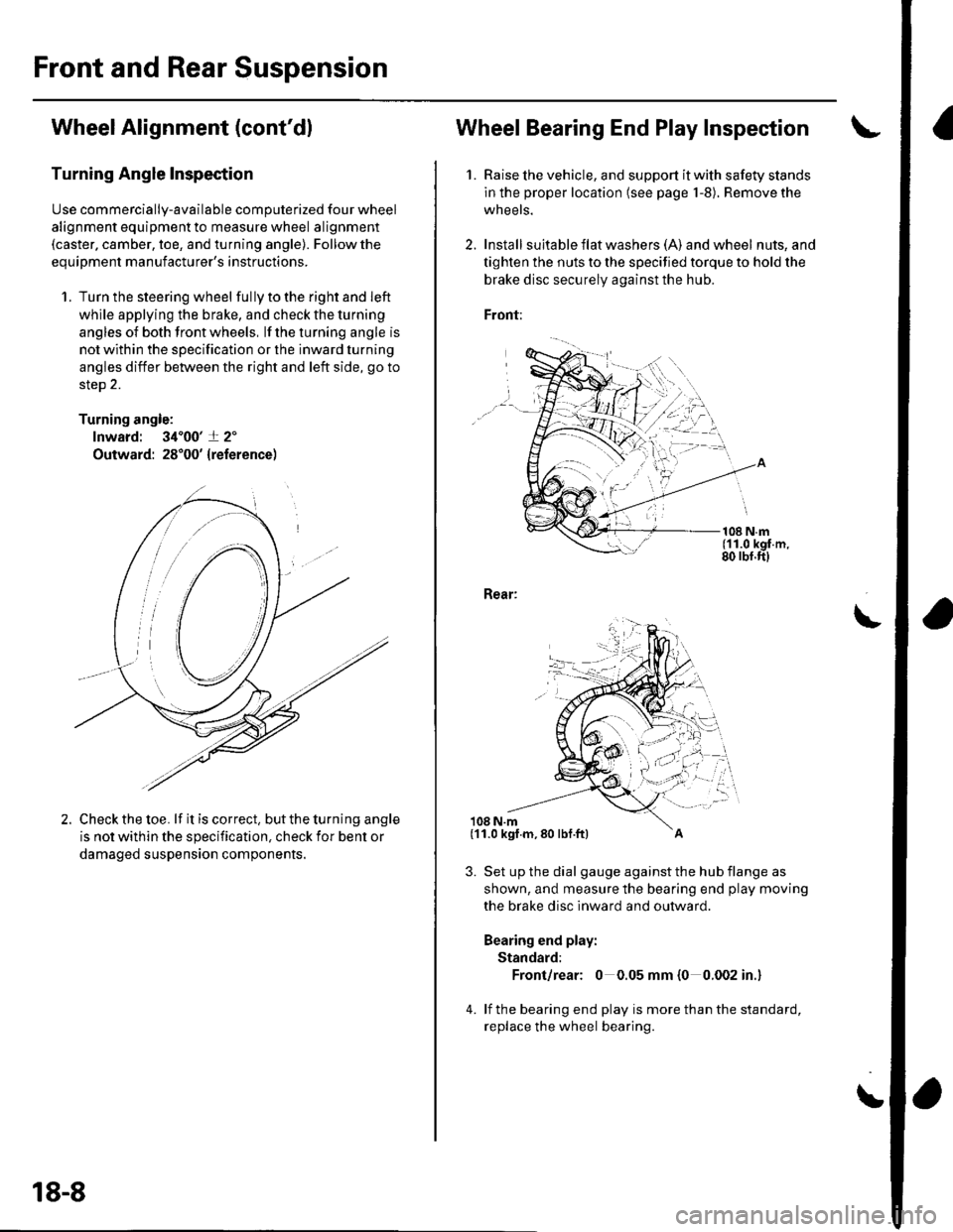
1. Turn the steering wheel fullytotherightandleft
while applying the brake, and check the turning
angles of both front wheels, lf the turning angle is
not within the specification or the inward turning
angles differ between the right and left side, go to
steD 2.
Turning angle:
lnward: 34'00'+ 2'
Outward: 28'00' {reference)
Check the toe. lf it is correct, but the turning angle
is not within the specification, check ior bent or
damaged suspension components,
18-8
Wheel Bearing End Play Inspec'tion
1. Raise lhe vehicle, and support it with safety stands
in the proper location (see page 1-8). Remove the
wheels.
2. Install suita ble f lat washe rs (A) and wheel nuts, and
tighten the nuts to the specified torque to hold the
brake disc securely against the hub.
Front:
108 N.m(11.0 kgf.m,80 rbf.ft)
Rear:
108 N.m
3. Set up the dial gauge against the hub flange as
shown, and measure the bearing end play moving
the brake disc inward and outward.
Bearing end play:
Standard:
Front/rear: 0 0.05 mm {0 0.002 in.}
4. lf the bearing end play is more than the standard,
replace the wheel bearing.
\
(11.0 kgf.m,80 lbf.ft)
Page 573 of 1139
18.
19.
Wash the knuckle and hub thoroughly in hlgh flash
point solvent before reassembly.
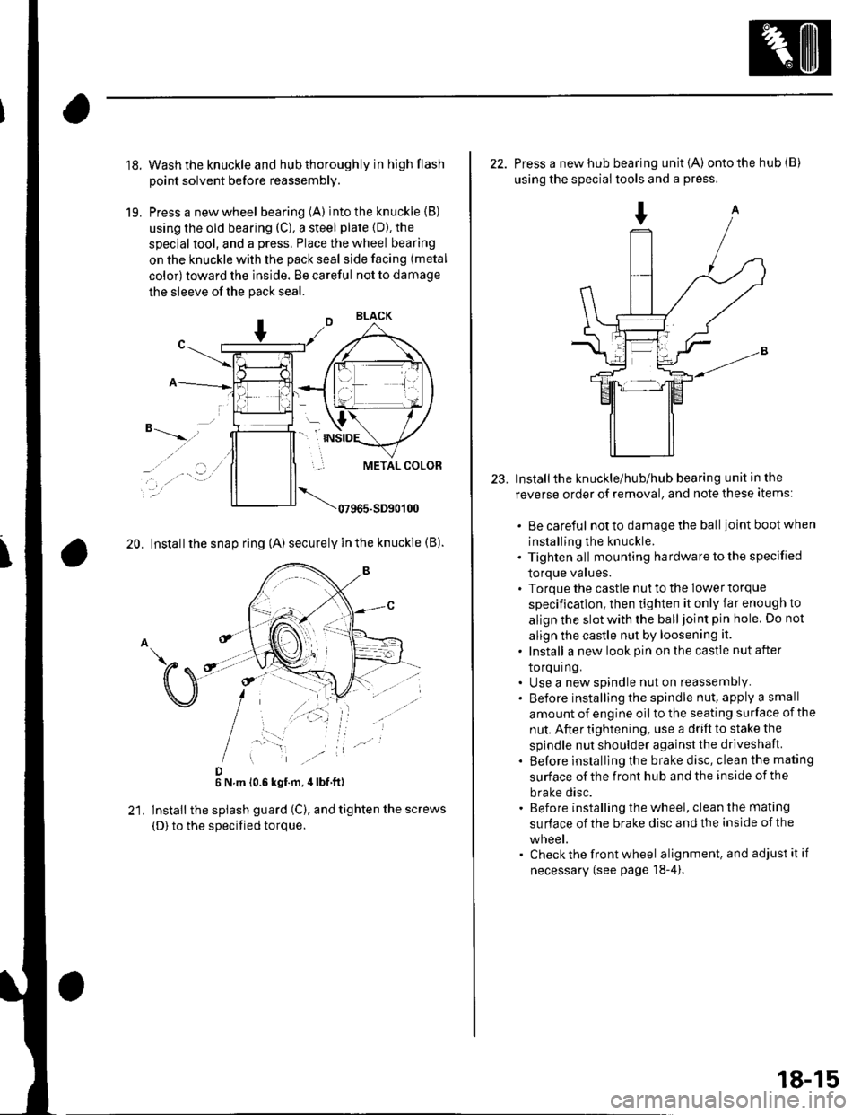
Press a new wheel bearing (A) into the knuckle (B)
using the old bearing (C), a steel plate {D). the
special tool, and a press. Place the wheel bearing
on the knuckle with the pack seal side facing (metal
color) toward the inside. Be careful not to damage
the sleeve of the pack seal.
"-t-_"*,,''
_, .' . . a-�.) ../
..-.
20. Install the snap ring (A) securely in the knuckle (B).
D6 N.m 10.6 kgf.m,4lbf ft)
lnstall the splash guard (C), and tighten the screws
(D) to the specified torque.
23.
22. Press a new hub bearing unit {A) ontothehub(B)
using the special tools and a press.
Installthe knuckle/hub/hub bearing unit in the
reverse order of removal, and note these items:
. Be careful notto damagethe balljoint bootwhen
installing the knuckle.. Tighten all mounting hardware to the specified
lOrque values.. Torque the castle nut to the lower torque
specification, then tighten it only far enough to
align the slot with the ball joint pin hole. Do not
align the castle nut by loosening it.
. Install a new look pin on the castle nut after
torquing.. Use a new spindle nut on reassembly.. Before installing the spindle nut, apply a small
amount of engine oil to the seating surface of the
nut. After tightening, use a drift to stake the
spindle nut shoulder against the driveshaft.
. Before installlng the brake disc, clean the mating
surface of the front hub and the inside of the
brake disc.. Before installing the wheel, clean the mating
su rface of the brake disc and the inside of the
wneet.. Check the front wheel alignment, and adjust it if
necessary (see page 18-4).
18-15
Page 577 of 1139
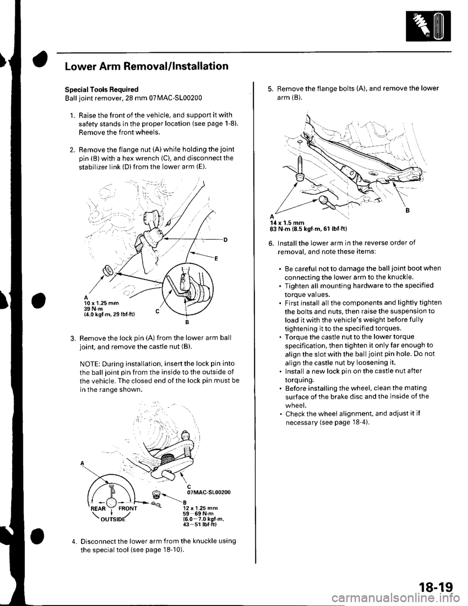
Lower Arm Removal/lnstallation
SpecialTools Required
Ball joint remover,2S mm 07|MAC-S100200
1. Raise the front of the vehicle, and support it with
safety stands in the proper location (see page 1-8).
Remove the front wheels.
Remove the flange nut (A) while holding the joint
pin {B) with a hex wrench (C), and disconnect the
stabilizer link (D)from the lower arm (E).
10 x 1.25 mm39 N.m{4.0 kgf m, 29 lbt.ft)
3.Remove the lock pin (A) from the lower arm ball
joint, and remove the castle nut (B).
NOTE: During installation, insertthe lock pin into
the ball joint pin from the inside to the outside of
the vehicle. The closed end of the lock pin must be
in the range shown.
6--__ oTMAc-sloo2oo
@a12 x 1.25 mm59 69Nm16.0-7.0 kgt-m,43 51 lbf.ft)
4.Disconnect the lower arm from the knuckle using
the special tool (see page 18-10).
5. Remove the flange bolts (A), and remove the lower
arm {B}.
14 x 1.5 mm83 N.m (8.5 kgf.m,61 lbf.ft)
6. Installthe lower arm in the reverse order of
removal, and note these items:
. Be careful not to damage the ball joint boot when
connecting the lower arm to the knuckle.
' Tighten all mounting hardware to the specified
torque values,. Firstinstall all the components and lightlytighten
the bolts and nuts. then raise the suspension to
load it with the vehicle's weight before fully
tightening it to the specified torques.. Torque the castle nut to the lower torque
specification, then tighten it only far enough to
align the slot with the ball joint pin hole. Do not
allgn the castle nut by loosening it.
. Install a new lock pin on the castle nut after
torquing.. Before installing the wheel, clean the mating
surface of the brake disc and the inside of the
wneet.. Check the wheel alignment, and adjustitif
necessary (see page '18-4).
18-19
Page 583 of 1139
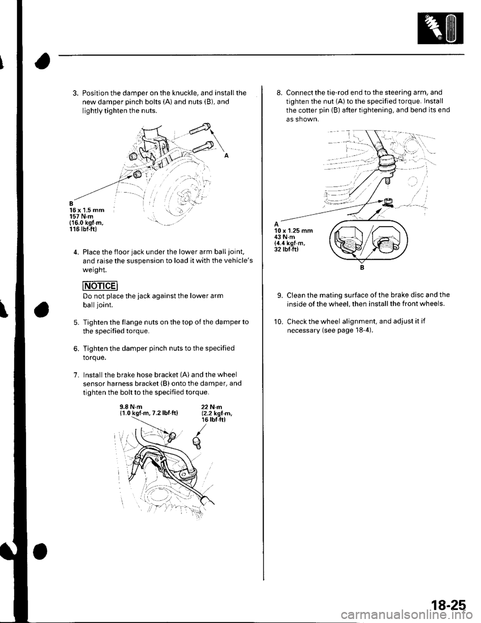
3. Position the damper on the knuckle, and installthe
new damper pinch bolts (A) and nuts (B), and
lightly tighten the nuts.
B16x 1,5 mm157 N.m(16.0 kgt m,116 tbt.ftl
4. Place the floor jack under the lower arm balljoint,
and raise the suspension to load it with the vehicle's
weight.
Do not place the jack against the lower arm
balljoint.
Tighten the flange nuts on the top of the damper to
the specified torque.
Tighten the damper pinch nuts to the specified
torque.
Install the brake hose bracket (A) and the wheel
sensor harness bracket (B) onto the damper, and
tighten the bolt to the specified torque.
5.
1.
9.8 N.m11.0 kgf.m, 7.2lbf.ftl22N|rl.12.2 kgI m,16 rbr,ftl
q
8. Connect the tie-rod end to the steering arm, and
tighten the nut (A) to the specified torque. Install
the cotter pin (B) after tightening, and bend lts end
as shown.
9. Clean the mating surface ofthe brake disc and the
inside of the wheel, then install the front wheels.
10. Check the wheel alignment, and adjustitif
necessary {see page 18-4).
18-25
Page 587 of 1139
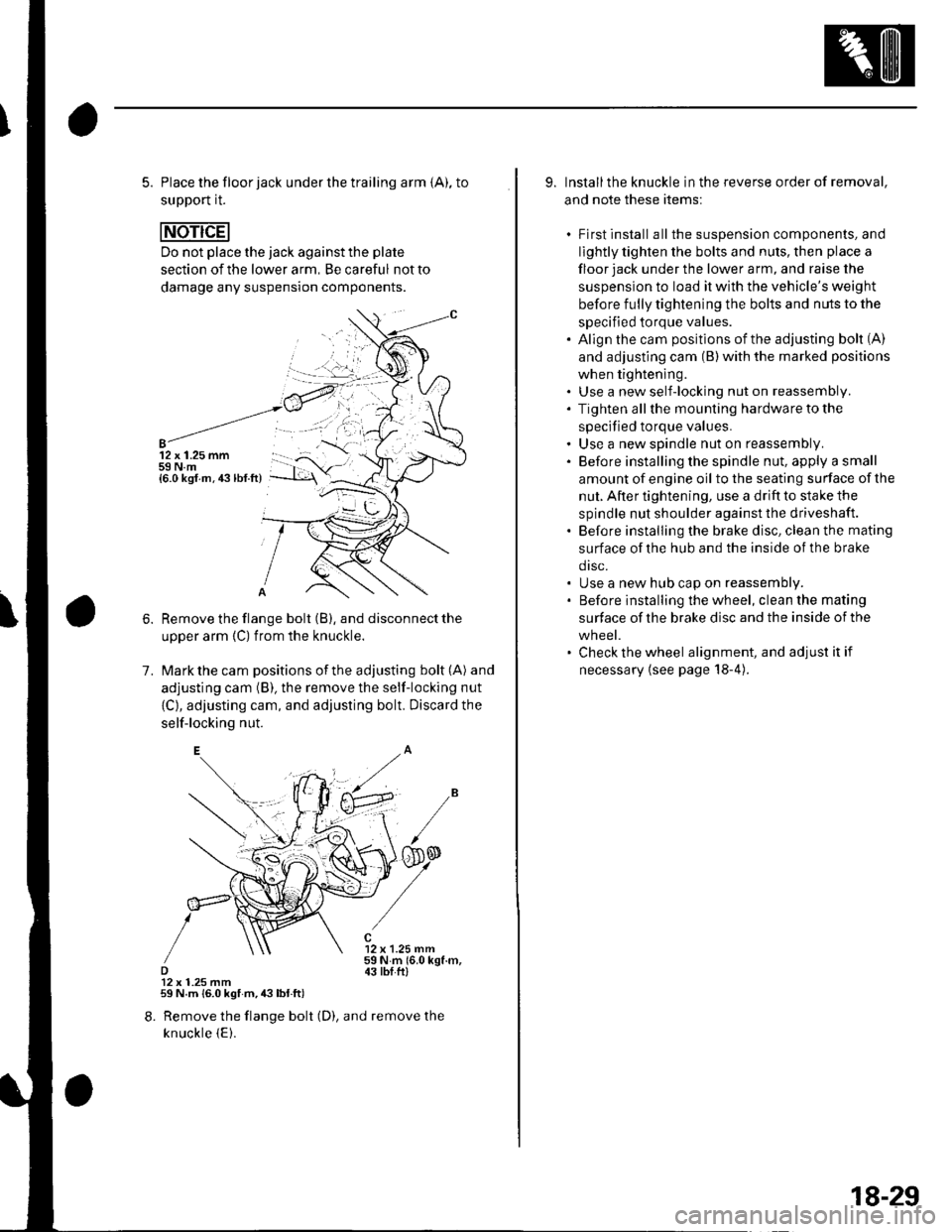
5. Place the floor jack under the trailing arm {A), to
support it.
Do not place the jack against the plate
section of the lower arm, Be careful not to
damage any suspension components.
12 x 1.25 mm59 N.m{6.0 ksf.m.43lbf.ft)
1.
Remove the flange bolt (B), and disconnect the
upper arm {C) from the knuckle.
Mark the cam positions of the adjusting bolt (A) and
adjusting cam (B), the remove the self-locking nut
{C}, adjusting cam, and adjusting bolt. Discard the
self-locking nut.
12 x 1.25 mm59Nm(6.0kgf.m,43 tbI.ftl12 x 1.25 mm59 N.m {6.0 kgf m,43lbl.ft)
8. Remove the flange bolt (D), and remove the
knuckle {E).
9. Installthe knuckle in the reverse order of removal,
and note these items:
. First install all the suspension components, and
lightly tighten the bolts and nuls, then place a
floor jack under the lower a rm, and raise the
suspension to load it with the vehicle's weight
before fully tightening the bolts and nuts to the
specified torque values.. Align the cam positions of the adjusting bolt (A)
and adjusting cam (B) with the marked positions
when tightening.. Use a new self-locking nut on reassembly.. Tighten allthe mounting hardware to the
specified torque values.. Use a new spindle nut on reassembly.. Before installing the spindle nut, apply a small
amount of engine oil to the seating surface of the
nut. After tightening, use a drift to stake the
spindle nut shoulder against the driveshaft.. Before installing the brake disc, clean the mating
surface of the hub and the inside of the brake
drsc.. Use a new hub cap on reassembly.. Before installing the wheel, clean the mating
surface of the brake disc and the inside of the
wheel.. Check the wheel alignment, and adjust it if
necessary {see page 18-4).
18-29
Page 590 of 1139
Rear Suspension
Upper Arm Removal/lnstallation
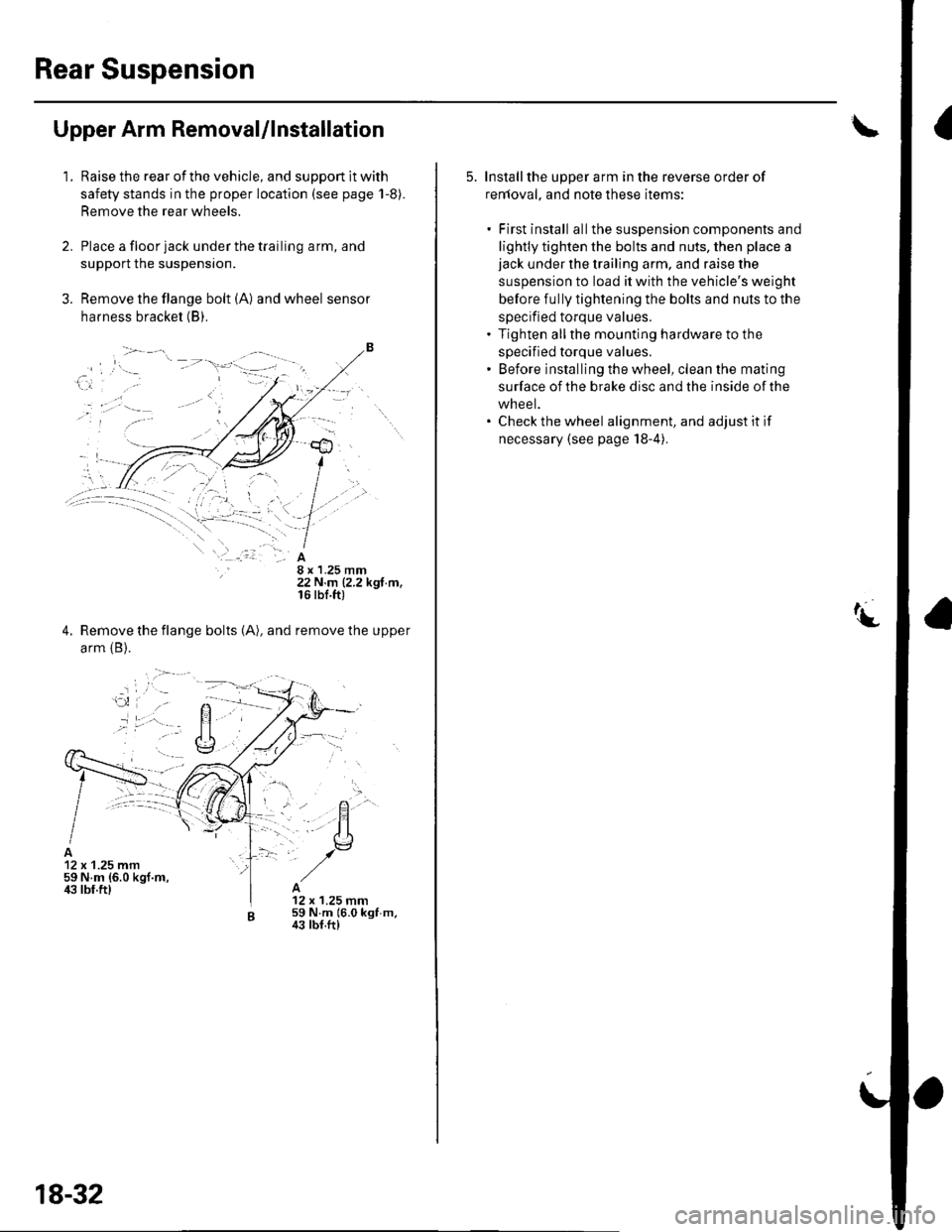
1.Raise the rear of the vehicle, and support lt with
safety stands in the proper location (see page 1-8).
Remove the rear wheels.
Place a floor jack under the trailing arm, and
support the suspensron.
Remove the flange bolt (A) and wheel sensor
harness bracket (B).
8 x 1.25 mm22 N.m (2.2 kgf.m,16 rbf.ft)
Remove the flange bolts (A), and remove the upper
arm {B).
12 x 1.25 mm59 N.m {6.0 kgf.m,ir3 lbf.ft)12 x 1.25 mm59 N.m 16.0 kgf m,43 tbf.ft)
18-32
5. Installthe upper arm in the reverse order of
renloval, and note these items:
. First install allthe suspension components and
lightly tighten the bolts and nuts, then place ajack under the trailing arm, and raise the
suspension to load it with the vehicle's weight
before fully tightening the bolts and nuts to the
specified torque values.. Tighten allthe mounting hardware to the
specified torque values.' Before installing the wheel, clean the mating
surface of the brake disc and the inside of the
wheel.. Check the wheel alignment, and adjust it if
necessary (see page 18-4).
Page 591 of 1139
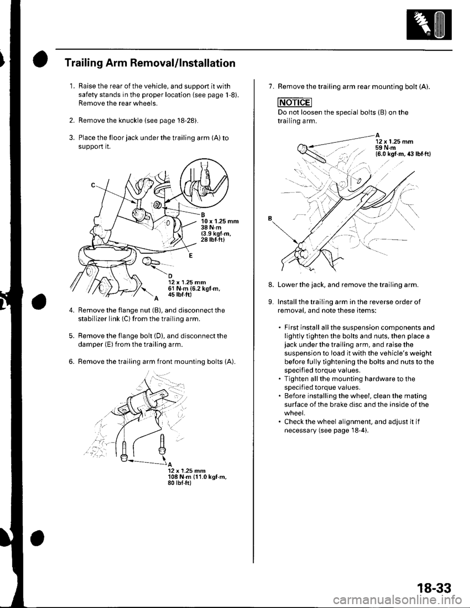
3.
Trailing Arm Removal/lnstallation
1.Raise the rear of the vehicle, and suppon it with
safety stands in the proper location (see page 1,8).
Remove the rear wheels.
Remove the knuckle (see page 18-28).
Place the floor jack under the trailing arm (A) to
support it.
B10 x 1.25 mm38Nm(3.9 kgl.m,28 tbf.ftl
12 x 1.25 mm61 N m (6.2 kgt m.
A 4s tbf,ft)
Remove the flange nut (B), and disconnect the
stabilizer link (C) from the trailing arm.
Remove the flange bolt {D), and disconnect the
damper (E) from the trailing arm.
Remove the trailing arm front mounting bolts (A).
A12 x 1.25 Jnm108 N.m {11.0 kgt.m,80 tbf.ft)
,'a':r -
7. Remove the trailing arm rear mounting bolt (A).
Do not loosen the special bolts (B) on the
trailing arm.
A12 x 1.25 mm59 N.m
-----\':,'.ttg
'.,--1..-r.':1
Lower the jack, and remove the trailing arm.
Install the trailing arm in the reverse order of
removal, and note these items:
. First install allthe suspension components and
lightly tlghten the bolts and nuts, then place ajack under the trailing arm, and raise the
suspension to load it with the vehicle's weight
before fully tightening the bolts and nuts to the
specified torque values.. Tighten allthe mounting hardware to the
specif ied torque values.. Before installing the wheel, clean the mating
surface of the brake disc and the inside of the
wneei.. Check the wheel alignment, and adjust it if
necessary (see page'18-4).
8.
9.
18-33
Page 595 of 1139
D
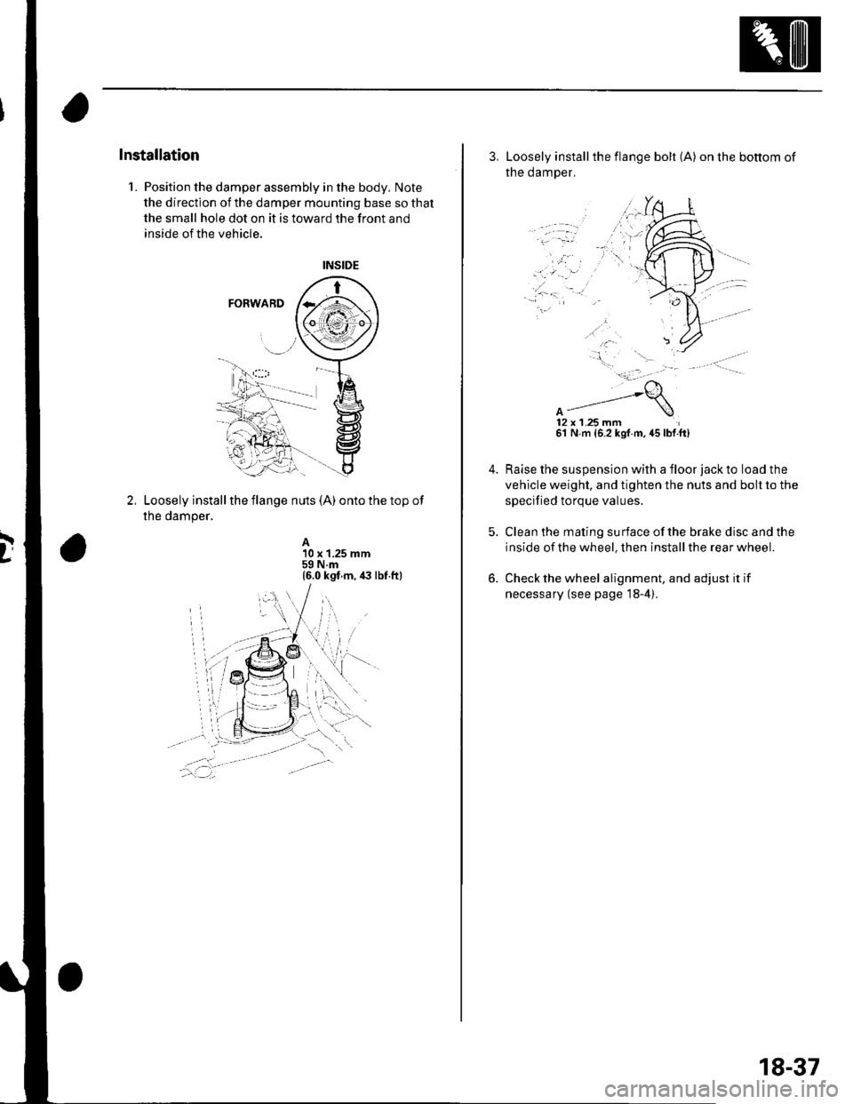
Installation
1. Position the damper assembly in the body. Note
the direction of the damper mounting base so that
the small hole dot on it is toward the front and
inside of the vehicle.
Loosely install the flange nuts (A) onto the top of
the damper,
A10 x 1.25 mm59 N.m16.0 kgt.m, ia lbt ft)
3. Loosely installthe flange bolt (A) on the bottom of
the damper.
12x 1.25 mm61 N m {6.2 kgf.m. 45 lbf.ft)
Raise the suspension with a floor jack to load the
vehicle weight, and tighten the nuts and bolt to the
specified torque values.
Clean the mating surface ofthe brake disc and the
inside of the wheel, then install the rear wheel.
Check the wheel alignment, and adjust it if
necessary (see page 18-4).
18-37
Page 754 of 1139
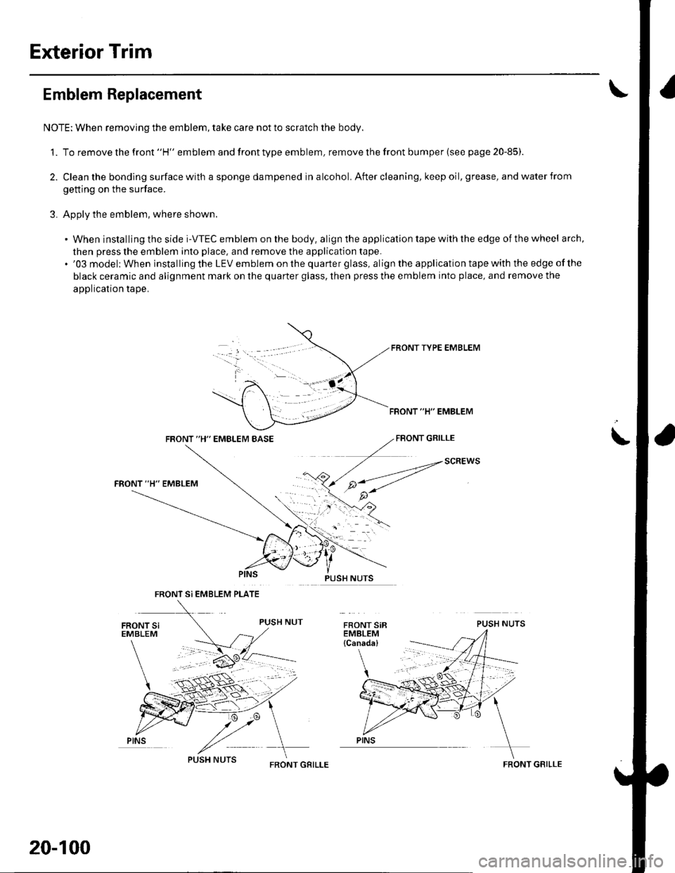
Exterior Trim
Emblem Replacement
NOTE: When removing the emblem, take care not to scratch the body.
1. To remove the front "H" emblem and front type emblem, remove the front bumper (see page 20-85)
2. Clean the bonding surface with a sponge dampened in alcohol. After cleaning, keep oil, grease, and water from
getting on the surface.
3. Apply the emblem, where shown.
. When installing the side i-VTEC emblem on the body, align the application tape with the edge of the wheel arch,
then press the emblem into place, and remove the application tape.. '03 model: When installing the LEV emblem on the quarter glass, align the application tape with the edge of the
black ceramic and alignment mark on the quarter glass, then press the emblem into place, and remove the
application tape.
FRONT TYPE EMBLEM
FBONT "H" EMBLEM
FRONT "H" EMBLEM BASEFBONT GRILLE
PUSH NUTS
i
SCREWS
FRONT Si EMBLEM PLATE
PINS
20-100
FRONT GRILLEFRONT GRILLE