Cmp sensor HONDA CIVIC 2002 7.G Owner's Manual
[x] Cancel search | Manufacturer: HONDA, Model Year: 2002, Model line: CIVIC, Model: HONDA CIVIC 2002 7.GPages: 1139, PDF Size: 28.19 MB
Page 324 of 1139
VTEC/VTC
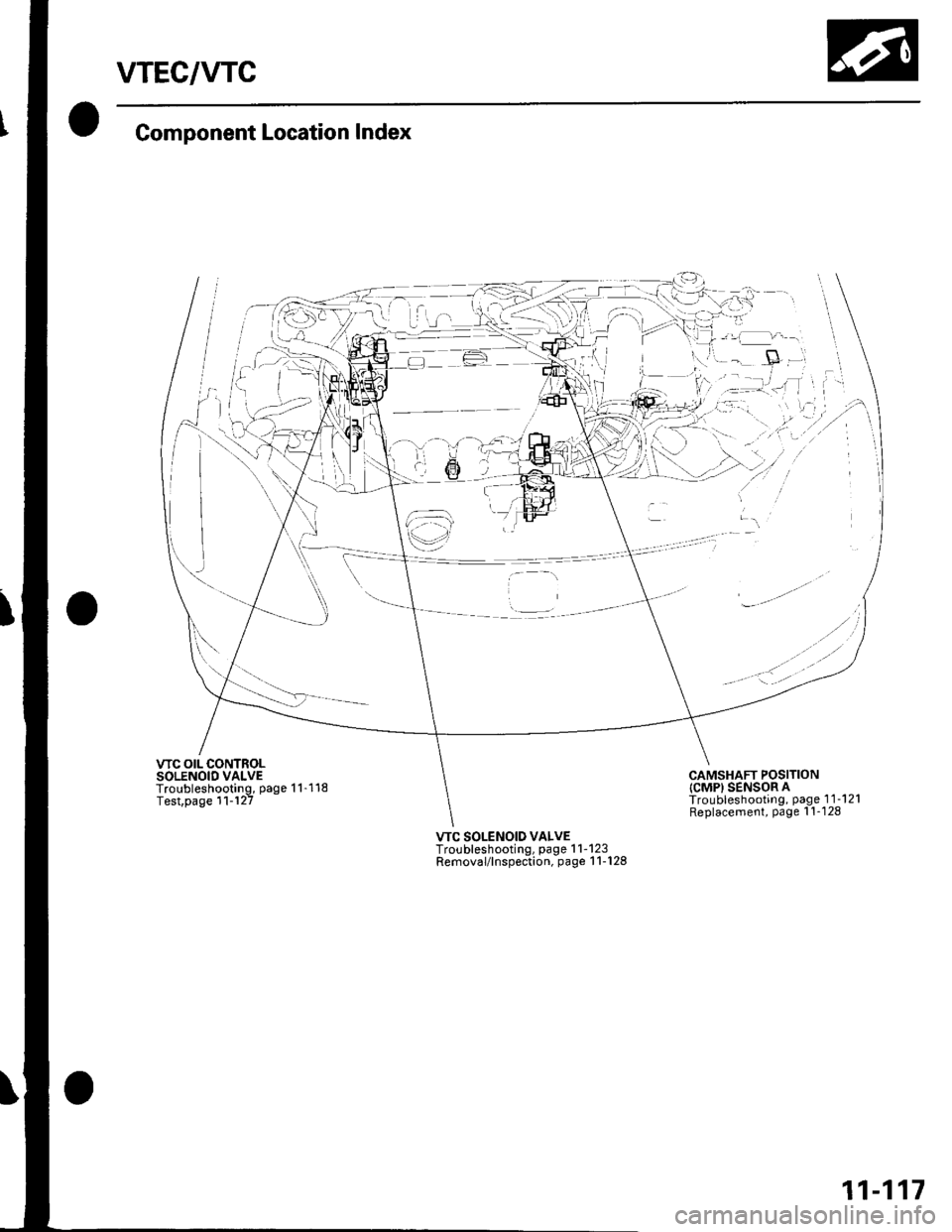
Component Location Index
VTC OIL CONTROLSOLENOID VALVETroubleshooting, page 1 1-118Test,page 11-'l27
-gl
:1
iai- r-:
@'-;'
;'l--i -
lt i..,,--tl
€)
,..
'- tt /
. -' '--'-
CAMSHAFT POSITIONICMPI SENSOR ATroubleshooting, page 1 1-121Replacement, Page l'!-128
VTC SOLENOID VALVETroubleshooting, page 1 1-123Removal/lnspection, page 1 1-128
11-117
Page 328 of 1139
DTC P0340: CMP Sensor A No Signal
DTG P0344: CMP Sensor A Intermittent
Interruption
1. Reset the ECM (see page '11-4).
2. Start the engine.
ls DTC P0340 and/or P0344 indicated?
YES-Go to step 3.
NO Intermittent failure, system is OK at this time.
Check for poor connections or loose terminals at
the CMP sensor A and at the ECM.I
3. Turn the ignition switch OFF.
4. Disconnect the CMP sensor A 3P connector.
5. Turn the ignition switch ON (ll).
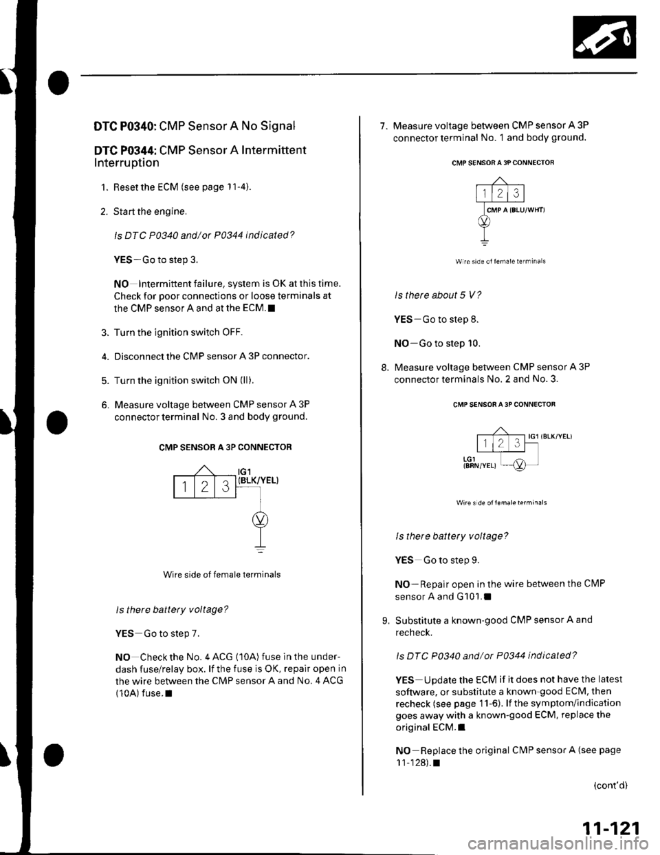
6. Measure voltage between CMP sensor A 3P
connector terminal No. 3 and body ground.
CMP SENSOR A 3P CONNECTOR
(BLK/YEL}
Wire side of female terminals
ls there battety voltage?
YES Go to step 7.
NO Check the No. 4 ACG {10A) fuse in the under-
dash fuse/relay box. lf the fuse is OK, repair open in
the wire between the CN4P sensor A and No. 4 ACG
(10A) fuse.I
tG1
123
7. Measure voltage between CMP sensor A 3P
connector terminal No. 1 and body ground.
CMP SENSORA 3P CONNECTOR
Wire side olfemale termina s
ls therc about 5 V?
YES-Go to step 8.
NO-Go to step 10.
8. Measure voltage between CMP sensor A 3P
connector terminals No. 2 and No. 3.
CMP SENSOR A 3P CONNECTOF
;f-;-1 ,o, ,r.*,"r.,
I l1 J l-t
,-or---T--I{8RN/YEL) ni-
ls there battety voltage?
YES Go to step 9.
NO-Repair open in the wire between the Cl\4P
sensor A and G101.1
9. Substitute a known-good CMP sensor A and
recheck.
ls DTC P0340 and/ot P0344 indicated?
YES Update the ECM if it does not have the latest
software, or substitute a known-good ECM, then
recheck (see page 11-6). lf the symptom/indication
goes away with a known-good ECM, replace the
original ECM.I
NO Replace the original CMP sensor A {see page
11-128).t
(cont'd)
11-121
Page 329 of 1139
VTEC/VTC
10.
DTC Troubleshooting (cont'd)
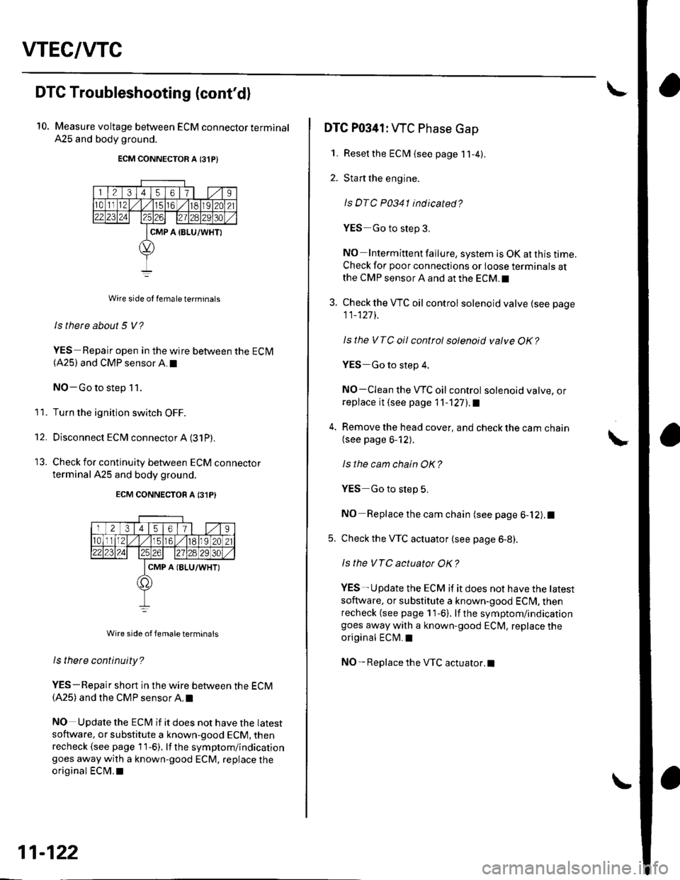
Measure voltage between ECM connector terminal
A25 and body ground.
ECM CONNECTOR A 131P)
Wire side of female te.minals
ls there about 5 V?
YES-Repair open in the wire between the ECM(A25) and CMP sensor A.I
NO-Go to step 11.
Turn the ignition switch OFF.
Disconnect ECM connector A (31P)
Check for continuity between ECM connecror
terminal A25 and body ground.
ECM CONNECTON A 131P}
Wire side of femaleterminals
ls tnere continuity?
YES-Repair short in the wire between the ECM(A25) and the CMP sensor A. t
NO Update the ECt\4 if it does not have the latest
software, or substitute a known-good ECM, thenrecheck (see page 1 1-6). lf the symptom/indicationgoes away with a known-good ECM, replace the
original ECM.I
11.
't2.
11-122
DTC P0341: WC Phase Gap
1. Resetthe ECM {see page 11-4).
2. Start the engine.
ls DTC P0341 indicated?
YES Go to step 3.
NO Intermittent failure, system is OK at this time.Check for poor connections or loose terminals atthe CMP sensor A and at the ECM.I
3. Check the VTC oil control solenoid valve (see page
11_127]-.
Isthe VTC oil control solenoid valve OK?
YES-Go to step 4.
NO-CIean the VTC oil control solenoid valve, orreplace it (see page 11-'l27l.a
4. Remove the head cover, and check the cam chain
{see page 6-12).
ls the cam chain OK?
YES Go to slep 5.
NO Replace the cam chain (see page 6-12).1
5. Check the VTC actuator (see page 6-8).
ls the VTC actuator OK?
YES- U pdate the ECM if it does not have the tatest
soflware, or substitute a known-good ECI\4, thenrecheck (see page 11-6). lf the symptom/indicationgoes away with a known-good ECM, replace the
original ECM.I
NO- Replace the VTC actuator.l
Page 335 of 1139
VTEC/WC
1.
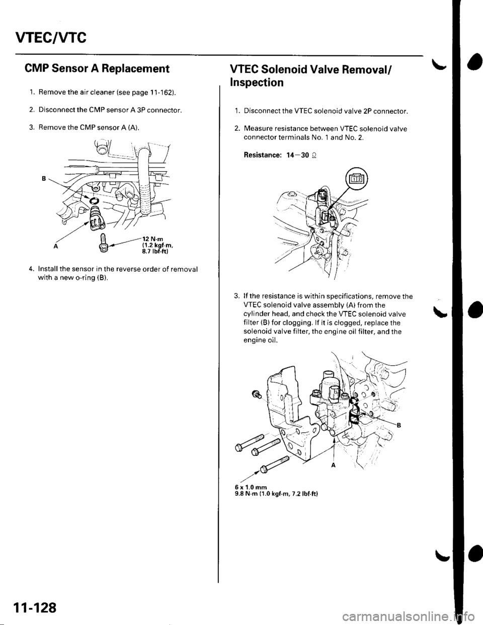
CMP Sensor A Replacement
Remove the air cleaner (see page 1 1-162).
Disconnect the CMP sensor A 3P connector.
Remove the CMP sensor A (A).
Installthe sensor in the reverse order of removal
with a new o-ring (B).
B-'-----'-l:,",14*
11-128
WEC Solenoid Valve Removal/
Inspection
1.Disconnect the VTEC solenoid valve 2P connector.
Measure resistance between VTEC solenoid valve
connector terminals No. 1 and No. 2.
Resistance: 14-30 Q
3. lf the resistance is within specifications, remove the
VTEC solenoid valve assemblv (A)from the
cylinder head, and check the VTEC solenoid valve
filter (B)for clogging. lf it is clogged, replace the
solenoid valve filter, the engine oilfilter, and the
engine oil.
6x1.0mm9.8 N.m (1.0 kgf.m, 7,2 lbf.ftl
L
Page 847 of 1139
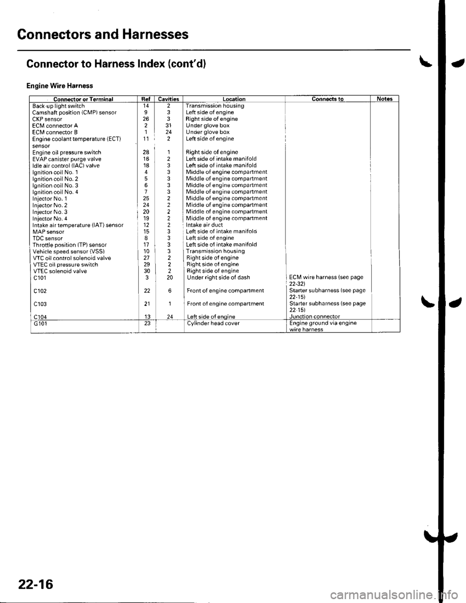
Connectors and Harnesses
Engine Wire Harness
Camshaft position (CMP) sensorLllr sensorEC[,4 connector AECI/l connector BEngine coolant temperature (ECT)
sensorEngine oil pressure switchEVAP canister purge valveldle air control (lAC)valve
lgnition coil No. llgnition coil No. 2lgnition coil No. 3lgnition coil No. 4Iniector No. 1Inlector No.2Iniector No.3Iniector No. 4Intake air temperature {lAT) sensor
TDC sensorThrottle position (TP) sensorVehicle speed sensor (VSSI
VTC oil control solenoid valveVTEC oil pressure switchVTEC solenoid valvec 101
c102
233
242
Transmission housingLeft side of engineRight side ofengineUnder glove boxUnder glove boxLeft side of engine
Bight side oI engineLeft side of intake manifoldLeft side of intake manifoldMiddle of engine compartmentMiddle of engine compartmentMiddle of engine compartmentMiddle of engine compartmentMiddle of engine compartmentMiddle of engine compartmentMiddle of engine compartmentMiddle of engine companment
28
1845672524201912
811102729303
22
12333332222233
322220
Left side of intake manifoldLeft side of engineLeft side of intake manifoldTransmission housingRight side o{ engineRight side of engineRight side of engineUnder right side of dash
Front of engine companment
Front of engine compartment
ECM wire harness {see page22-321Starter subharness (see page22-15)Starter subharness (see page22 151
Connector to Harness Index (cont'dl
22-16
Page 878 of 1139
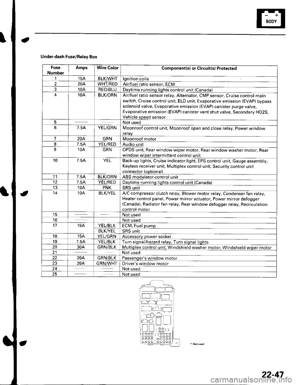
Under-dash Fuse/Relay Box
Fuse
Number
AmpsWire ColorComponent(s) or Circuit(s) Protected
115ABLKA/VHTlgnition coils
2204WHT/REDAirlfuel ratio sensor, ECM
310ARED/BLUDaytime running Iights control unit {Canada)10ABLI(ORNAir/fuel ratio sensor relay, Alternator, CMP sensor, Cruise control main
switch, Cruise control unit. ELD unit, Evaporative emission (EVAP) bypass
solenoid valve, Evaporative emission (EVAP)canister purge valve,
Evaporative emission (EVAP) canister vent shut valve, Secondary H02S,
Vehicle speed sensor
5Not used
67.5AYEUGRNMoonroof control unit, Moonroof open and close relay, Power window
relaV
7204GRNMoonroof motor
I7.5AYEUREDAudio unit
910AGRNOPDS unit, Rear window wiper motor, Rear window washer motor, Rear
window wiper intermittent control unit
107.54YELBack-up lights, Cruise indicator light, EPS control unit, Gauge assembly,
Keyless receiver unit, Multiplex control unit, Security control unit
connector (optional)
117.5ABLIVORNABS modulator-control unit
127.5AYEUREDDaytime runnino liohts control unit (Canada)
1310APNKSRS unit't410ABLK/YE LA,,/C compressor clutch relay, Blower motor relay, Condenser fan relay,
Heater control panel, Power mirror actuator, Power mirror defogger(Canada), Radiator fan relay, Rear window defogger relay, Recirculation
control motor1ENot used
loNot used
1715AYE L/B LKECM, Fuel pump
B LK/YE L>H> Unrr
1815AYEUGRNAccessory power socket
197.5AYEUBLKTurn siqnal/hazard relav, Turn siqnal liohts
2030AGRN/BLKMultiplex control unit, Windshield washer motor. Windshield wioer motor21Not used
22204GRN/BLKPassenqer's window motor
2320A.G R N,A/VHTDriver's window motor
24Not used
25Not used
__^:Hr tl_l
f at-t
at I
r^,rl fl
!!;r -
!339,i;s!!sf Fnf : |rnITf
22-47
Page 879 of 1139
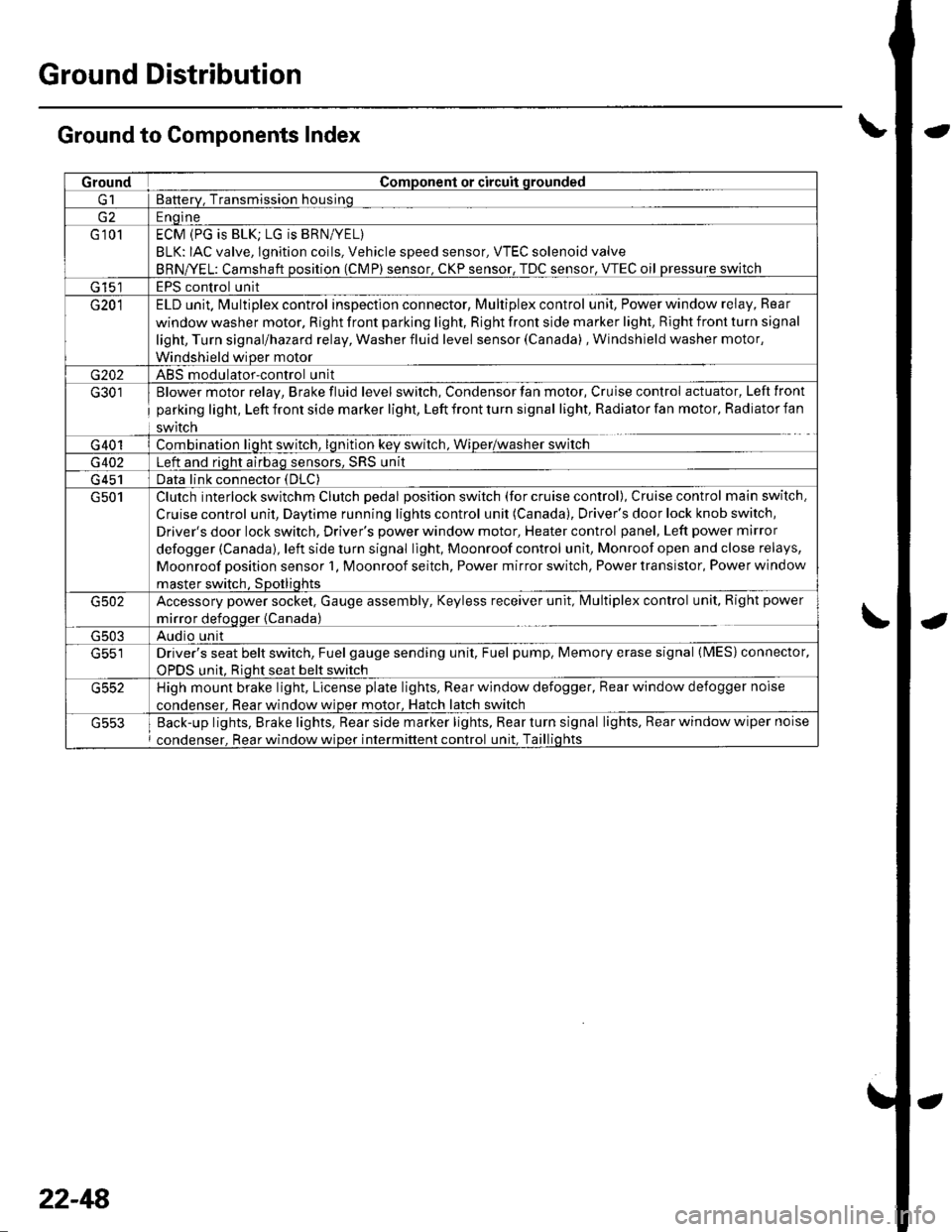
Ground Distribution
Ground to Components Index
GroundComponent or circuit qrounded
Batterv, Transmission housinq
E ngine
G 101ECM (PG is BLK; LG is BRN/YEL)
BLK: IAC valve, lgnition coils, Vehicle speed sensor, VTEC solenoid valve
BRNA/EL: Camshaft oosition (CMP) sensor. CKP sensor, TDC sensor. VTEC oil pressure switch
G 15'�]EPS control unit
G201ELD unit. Multiplex control inspection connector, Multiplex control unit, Power window relay, Rear
window washer motor, Right front parking light, Right front side marker light, Right front turn signal
light, Turn signal/hazard relay, Washer fluid level sensor (Canada) , Windshield washer motor,
Windshield wiDer motor
G202ABS modulator-control unit
G301
G401
Blower motor relay, Brake fluid level switch, Condensor fan motor, Cruise control actuator, Left front
parking light, Left front side marker light, Left front turn signal light, Radiator fan motor, Radiator fan
swrtcn
Combination liqht switch, lqnitlon kev srvitch, Wiper/wasfrer sr,virch
G402Left and riqht airbaq sensors, SRS unit
G 451Data link connector (DLC)
G501Clutch interlock switchm Clutch pedal position switch (for cruise control), Cruise control main switch,
Cruise control unit, Daytime running lights control unit (Canada), Driver's door lock knob switch,
Driver's door lock switch, Driver's power window motor, Heater control panel, Left power mirror
defogger (Canada), left side turn signal light, Moonroof control unit, Monroof open and close relays,
Moonroof position sensor '1, Moonroof seitch, Power mirror switch, Power transistor, Power window
master switch. SDotliqhts
G502Accessory power socket, Gauge assembly, Keyless receiver unit, lvlultiplex control unit, Right power
mirror defogger {Canada)
G503Audio unit
G551Driver's seat belt switch, Fuel gauge sending unit, Fuel pump, Memory erase signal (IMES) connector,
OPDS unit. Rioht seat belt switch
G552High mount brake light, License plate lights, Rear window defogger, Rear window defogger noise
condenser. Rear window wioer motor, Hatch latch switch
Back-up lights, Brake lights, Rear side marker lights, Rear turn signal lights, Rear window wiper noise
condenser, Rear window wiper intermittent control unit, Taillights
22-48
Page 1134 of 1139
Service Manual Index
(cont'dl
Brake System Indicator CircuitCircuit DiagramConventional Brake Components..... 19-9TroubleshootingABS/TCS Components .... ....... ...... 19-55
Bulb, GeugeRep|acemenl................ .. ............2263
Bulb, HeadlightReplacement ......................................... 22-A1
Bumper, FrontRemoval/1nsra11ation ............................ 20 85
Bumper, RearRemoval/lnstallation... ... . .....20.86
Combination Light SwilchTesVReplacement ..............................22 80
Connecting Rod BearingsRep|acement...................... .......-....7-8
Connecting Rod Boltsf nspection ....................-.-.-.-.................... 7 -24
Connecting RodsInspection ........,,.,.,...,.,.,.,.,,,,.,,,.,.,.,.,.,.,.,.. 7 5
Connectors(See first page of this Index)
Conventional Brake Component3Component Location Index ................... 19'3Troub1eshootin9 ..................................... 19-4
Cylinder Head AssemblyComponent Location Index ..................... 6-3Inspection ................................................. 6 6Removal ..........&�23Insta11alion .............................................. 6 39
Cylinder Head Cover8emova1 ..............-.-................................. 6-22Installation ..............................................6-41
Cylinder Head, BareInspecton..,.....,.
D
c
Cable ReelReplacement....................................... 23-1 19
CamshaftInspection .......................-...-................... 6-29
Cargo Area LightTesVRep1acement ................................ 22-97
CarpetReplacement.....-...-..... ... ......-.20-55
Ceiling Light-estrReplacement ................................ 22.96
Charging SystemComponent Location Index................... 4-20Circuit Diagram ...................................... 4-21
19-8
CoolantInspection .................. ..... .. 106Replacement................. ... . .. 10 6
Coolant Temperature Gat|geTroub1eshootin9................................... 22 64
Cooling SyslemComponent Location Index................... 10-2
Countershaft BearingsReplacement............... ..................... 13-42
Cowl CoverReplacement............... .. ..... ....20-95
CrankshaftRemoval .................................................. 7 -12
Repair ..................
Inspec(on,,,,,........1 14
Dampers. FrontReplacement................ ..................... 18 20
Oampers, RearRep1acement......................................... 18-34
Dash VentsBemoval/lnstallation .-.......................... 20-64
DashboardBemoval/1nsta11ation ............................ 20-66
Oashboard Center PanelRemoval/1nstaf 1ation ............................ 20 62
Dashboard Lower CoverRemoval/lnstallation ...................... 20-59, 63
Dashboard Under CoverRemoval/lnstallation ............................ 20 60
Diff erential Carrier Bearings, M/TRep1acement,,......,...,...,.,.,,,.,.,,,........,.,. 13-54
Ditferential Oil Seals, M/T8ep1acement......................................... 13-55
Differential Pinion Gears, M/TInspection .,....-,.,,,.,..,.-,.,.........,.,.,,, 13 53
OLC CircuitTroubleshooting ................................ 1 1-109
Door GlassRep1acement.,.,,,,,,,,,,,.,,,,,,,,,,.,.,.,.,.,,,,,,.,, 20-9Adjustment. .. .....................20-11
Door Glass WeathelstripsReplacement .............-.. . . . ..........-......20 10
Door LatchesReplacement ..........-.-.............................. 20-7
Door Lock ActuatorsTest ...................................................... 22-154
Door Lock Knob SwitchesTest -......... . . . - . . . . . . . . ......22-160
Door Lock SwitchesTest ........... ............................ ............. 22-160
Door Outer HandlesRep1acemen1 ........................................... 20-6
3
Child Seat Tether AnchorRemoval/lnstaf lat;on .. ........................ 23 11
CKP (Crankshaft Position) SonsorReplacement....................................... 1 1-116
ClutchComponentLocation 1ndex................... 12-3Rep1acemen1........................................... 12-9
Clutch InteYlock SwitchTest.....-........-...-............. ...---.-.......4-6
Clutch Master CylinderReplacement........................................... 12 5
clutch PedalAdjustment ............................................. 12 4
Clutch Pedal Position SwitchTest.,.,,,,,.,,,.,.,,,,,,.,.,,,,,,,,,.,,,,,.. ......445
lnstallation.................. . ..... .....1-24
Crankshalt Main BearingsReplacement........-.-.................................. 7-6
CrankshaftOil Seal,Transmission End1nstanation .............................................. 7 28
Crankshafl PulleyRemoval/lnstallation -..................-.......... 6-1 1
Cruise Control Actuator
Troubleshooting
Clutch Slave CylindorBeplacemeit...
...................... 4-43
.......4-22
Test
12-1
RepIacement........................................... 4-44
Cruise Control Actuator CableAdjustment ............................................. 4 45
Cruise Control Main SwitchTesVRep1acement .................................. 4 42
Cruise Control Set/Resume/Cancel SwitchTesVRep1acement .................................. 4 42
Cruise Control SystomComponent Localion Inde\................... 4-36Circuit Diagram ....-................................. 4 37
Cruise Control UnitInputTest.............................. .. ...4,40CMP {Camshaft Positionl Senso]Replacement....-...-.............................. 1 1-128
CMP (TDC) SensorsReplacement............-.......................... 1 1 1 14