check engine light HONDA CIVIC 2002 7.G Workshop Manual
[x] Cancel search | Manufacturer: HONDA, Model Year: 2002, Model line: CIVIC, Model: HONDA CIVIC 2002 7.GPages: 1139, PDF Size: 28.19 MB
Page 33 of 1139
L
A
I
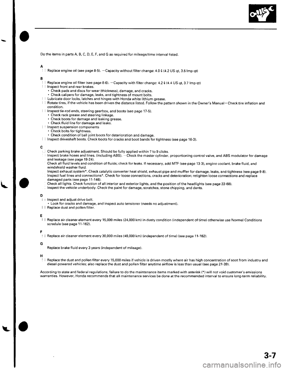
Do the items in parts A, B, C, D, E, F, and G as required for mileage/time interval listed.
Feplace engine oil(see pageS 5). Capacity withoutlilter change:4.0 q (4.2 US qt,3.5lmp qt)
Replace engjne oil filter (see page I 6). Capacity with filter change: 4.2 0 14.4 US qt, 3.7 lmp qt)Insoect front and rear brakes,. Check pads and discsforwearlthickness), damage, andcracks.. Check calipers for damage, leaks, and tightness of mount bolts.Lubricate door locks, latches and hinges with Honda white lithium grease.Rotate tires, if the vehicle has been driven the distance listed. Follow the pattern shown in the Owner's Manual-Check tire inflaron aoocondition,Inspecttie rod ends, steering gearbox, and boots (see page 17,5).. Check rack grease and steering linkage.. Check boots for damage and leaking grease.. Checklluid linefordamage and leaks.Inspect suspensron components. Check bolts for tightness.. Check condition of ball joint boots for deterioration and damage.Inspect driveshaft boots. Check boots for cracks and boot bands for tightness (see page 16-3).
Check parking brake adjustment. Should be fully applied within 7 to 9 clicks.Insp€ct brake hoses and lioes. (including ABS). Check the master cylinder, proportioning control valve, and ABS modulator for damageand leakage (see page 19-24).Check all fluid levels and condition ot lluids; check for leaks. lf necessary, add MTF (see page 13 3), engine coolant, brake fluid, andwindshield washer f luid.Inspect exhaust system*. Check catalytic converter heat shield, exhaust pipe and muffler for damage, leaks, and tightness (see page 9 8).Inspect fuel lines and connections*. Check for loose connections, cracks and deterioration; retighten loose connections and replacedamaged pans (seo page 11'146).Check alllights. Checkfunction otallinterior and exterior lights, andthe position ofthe headlights (see page 22-68).Inspect the v€hicle underbody. Check the paint for damage, scratches, stone chippin0, and dents.
L
D
E
F
H
InsDect and adiust drive belt.. Look tor cracks and damage, and inspect auto tensioner {needs no adjustment).Reolace dust and oollen filter.
Replace air cleaner element every 15,000 miles 124,000 km) in dustv condition {independent ol timei otherwise use Normal Conditionsscredule (see page 11-162).
lReplaceaircleanerelementevery30,000miles(48,000km)(independento{timei(seepagell-162).
Replace brake fluid every 3 years (independent oJ mileagei.
Replacethe dust and pollen Iilter every 15,000 miles ifvehicle is driven mostlywhere air has high concentration olsootfrom industryanddiesel powered vehiclesj also replace the dust and pollen filter anytime aarflow is less than ussal (see pags 21-39).
According to state and federal regulations, failure to do the maintenance items marked with asterisk (*) will not void customer's emissionswarranties. However, Honda recommends that all maintenance services be done at the recommended interval to ensure long-term reliability,
3-7
Page 35 of 1139
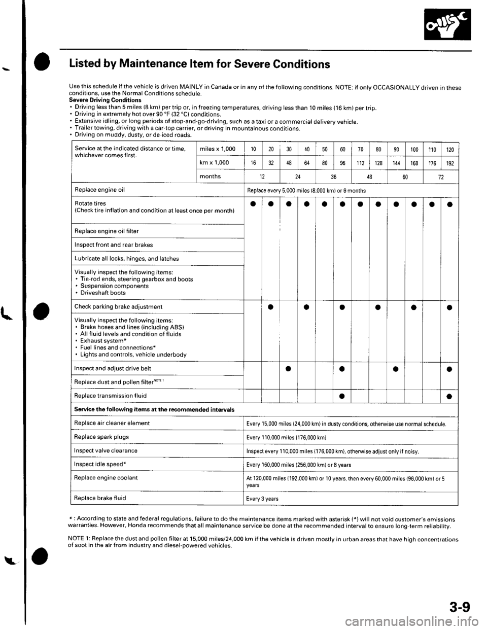
Listed by Maintenance ltem for Severe Conditions
Use this schedule if the vehicle is driven MAINLY in Canada or in anv of the followina conditions.NOTE: it only OCCASIONALLY driven in theseconditions, use the Normal Conditions schedute.Sovere Driving Conditions. Driving less than 5 miles (8 km) per trip or, in lreezing temperatures, driving less than. Driving in extremely hot over 90 "F 132 'C)conditions.10 miles (16 km) per trip.
. Extensive idling, or long periods ot stop-and-go-driving, such as a taxi or a commercial delivery vehicle.. Trailer towing, driving with a cartop carrier, or driving in mountainous conditions.. Driving on muddy, dusty, or de iced roads.
Service at the indicated distance or time,whichever comes first.miles x 1,000102030405060708090100110120
km x 1,0001648648096112128144160176192
months122436486072
Replace engine oilReplace every 5,000 miies 18,000 km)or 6 months
Rotate tires{Checktire intlation and condition at leastonce per monthiaoaaoaaoaaao
Replace engine oil fiher
Inspect front and rear brakes
Lubricate all locks, hinges, and latches
Visually inspect the following items:. Tie rod ends, steering gearbox and boots. Suspension components' Driveshaft boots
Checl parking brale adjuslmentaaOaoa
Visually inspect the following items:. Brake hoses and lines {including ABSi. Allfluid levels and condition oflluids. Exhaust system*. Fuel lines and connections*. Lights and controls, vehicle underbody
Inspect and adjust drive behoaoa
Replace dust and pollen filter"o't'
Replace transmission lluidaa
Service the following items atthe recommended interuals
Replace air cleaner elementEvery 15,000 miies (24,000 km) in dusty conditions, otheMise use normal schedule.
Replace spark plugsEvery 110,000 miles (176,000 km)
Inspect valve clearanceInspect every 110,000 miles (176,000 km), otheMise adiust only if noisy.
Inspect idle speed'Every 160,000 miles (256,000 km)or8 vears
Replace engine coolantAt 120,000 miles (192,000 km) of 10 years,lhen every 60,000 miles (96,000 km)or 5
Replace brake fluidEvery 3 years
* : According to state and federal regulations, failure to do the maintenance items marked with asterisk 1*)will not void customer's emissionswarranties. However, Honda recommends that all maintenance service be done at the recommended interval to ensure long{erm reliabilitv.
NOTE 1: Replace the dust and pollen filter at 15,000 miles/24,000 km if the vehicle is driven mostly in urban areas that have high concentrationsof soot in the air from industrv and diesel-Dowered vehicles.
t,
3-9
Page 52 of 1139
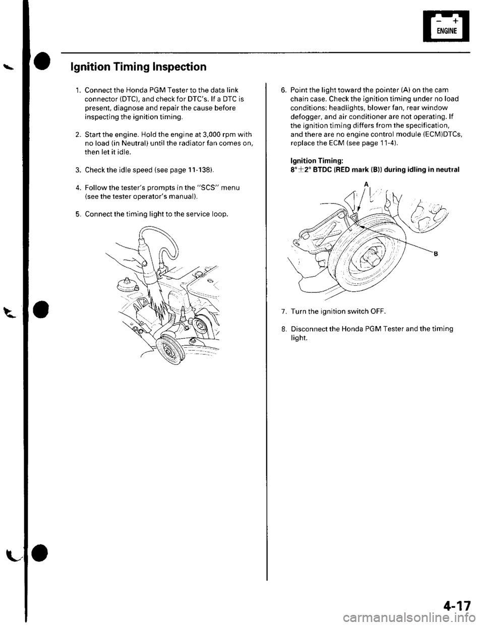
lgnition Timing Inspection
1.
4.
5.
Connect the Honda PGM Tester to the data link
connector (DTC), and check for DTC'S. lf a DTC is
present, diagnose and repair the cause before
inspecting the ignition timing.
Startthe engine. Hold the engine at 3,000 rpm with
no load (in Neutral) until the radiator fan comes on,
then let it idle.
Check the idle speed (see page 11-138).
Follow the tester's prompts in the "SCS" menu
{see the tester operator's manual),
Connect the timing light to the service loop.
o
6. Point the light toward the pointer (A) on the cam
chain case. Check the ignition timing under no load
conditions: headlights, blower fan. rear window
defogger, and air conditioner are not operaling. lf
the ignition timing differs from the specification,
and there are no engine control module {ECM)DTcs,
replace the ECM (see page 11-4)
lgnition Timing:
8"+2" BTDC {RED mark {B)) during idling in neutral
A
7. Turn the ignition switch OFF.
Disconnectthe Honda PGM Tester and thetiming
light.
4-17
Page 59 of 1139
Gharging System
Charging Circuit Troubleshooting (cont'd)
6. Start the engine. Hold the engine at 3,000 rpm with
no load (in Neutral) until the radiator fan comes on,
then let it idle.
7. Raise the engine speed to 2,000 rpm, and hold it
there.
8. Turn the headlights (high beam) on, and measure
voltage at the under-hood fuse/relay box terminal.
ls the voltage between 13.9 and 15.1 v?
YES-Go to step 9.
NO Repair or replace the alternator components
(see page 4-30).1
9. Read the amperage at '13.5 V.
NOTE: Adjust the voltage by turning the blower
motor, rear window defogger, brake lights. etc. ON.
ls the amperage 604 ot morc?
YES-Alternator/regulator operation is OK. I
NO Repair or replace the alternator components(see page 4-30).1
4-24
\,
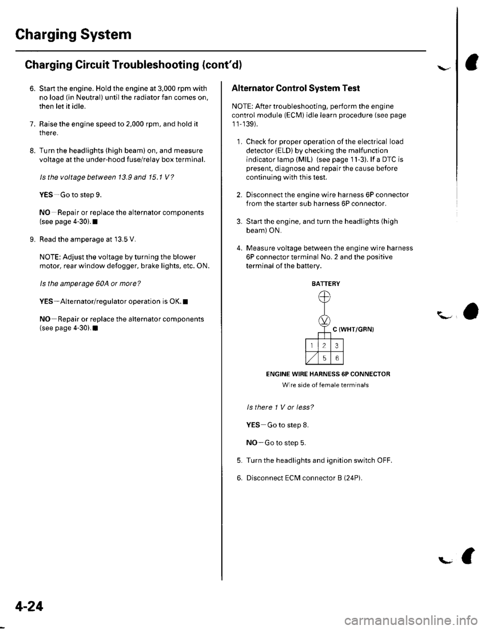
Alternator Control System Test
NOTE: After troubleshooting, perform the engine
control module (ECM) idle learn procedure (see page
11-139).
1 . Check for proper operation of the electrical load
detector (ELD) by checking the malfunction
indicator lamp (MlL) (see page 1 l-3). lf a DTC is
present, diagnose and repair the cause before
continuing with this test.
2. Disconnect the engine wire harness 6P connector
from the starter sub harness 6P connector.
3. Start the engine, and turn the headlights (high
beam) ON,
4. Measure voltage between the engine wire harness
6P connector terminal No. 2 and the positive
terminal of lhe battery.
C {WHT/GRN)
ENGINE WIRE HARNESS 6P CONNECTOR
Wire side of female terminals
ls there 1 V or less?
YES Go to step 8.
NO-Go to step 5.
Turn the headlights and ignition switch OFF.
Disconnect ECM connector B (24P).
5.
6.
BATTERY
Page 60 of 1139
\
L
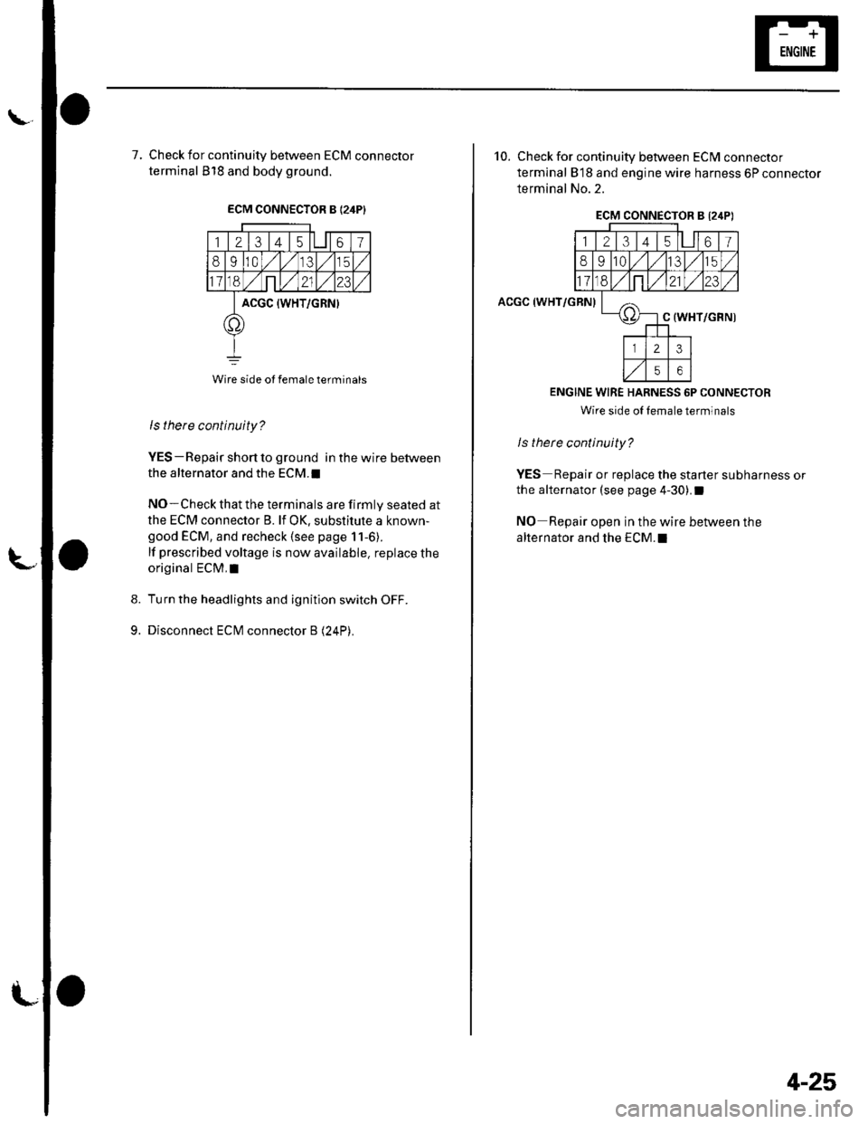
7, Check for continuity between ECM connector
terminal 818 and body ground.
ECM CONNECTOR B {24PI
123 t4 t561
8910,/1,/35
11ont,/2123
ACGC {WHT/GRN}
o
Wire side ot female terminals
9.
ls there continuity?
YES-Repair short to ground in the wire between
the alternator and the ECM.I
NO-Check that the terminals are firmly seated at
the ECM connector B. lf OK, substitute a known-
good ECM, and recheck (see page 11-6).
lf prescribed voltage is now available. replace the
original ECM,I
Turn the headlights and ignition switch OFF.
Disconnect ECM connector B (24P).
10. Check for continuity between ECM connector
terminal 818 and engine wire harness 6P connector
terminal No.2.
ACGC (WHT/GRN)
ECM CONNECTOR B l2,lPI
12314l5lll67
8910t.)15
11on2123
oC (WHT/GRN)
23
56
ENGINE WIRE HARNESS 6P CONNECTOR
Wire side oI lemale terminals
ls therc continuity?
YES Repair or replace the starter subharness or
the alternator (see page 4-30).I
NO Repair open in the wire between the
alternator and the ECM.I
4-25
Page 73 of 1139
Cruise Control
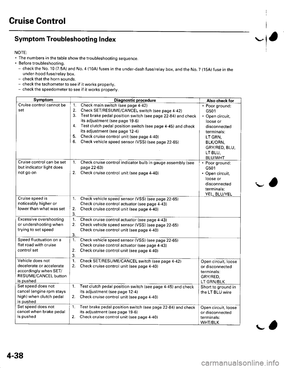
Symptom Troubleshooting Index
NOTE:' The numbers in the table showthetroubleshooting sequence.. Before troubleshooting.- check the No, 10 (7.5A) and No. 4 (10A) fuses in the under-dash fuse/relay box. and the No. 7 (15A) fuse in theunder-hood fuse/relay box,- check that the horn sounds.- check the tachometer to see if it works properly.- check the speedometer lo see if it works properly.
SymptomDiagnostic procedureAlso check forCruise control cannot be
set
1. Check main switch (see page 4-42)
2. Check SET/RESUME/CANCEL switch (see page 4-42)
3. Test brake pedal position switch (see page 22-84) and checkits adjustment {see page 19,6)
4. Test clutch pedal position switch (see page 4-45) and check
its adjustment (see page 12-41
5. Check cruise control unit {see page 4-40}
6. Check vehicle speed sensor (VSS) (see page 22-65)
. Poor ground:
G501. Open circuit,
loose or
disconnected
term inals:
LT GRN,
BLI(ORN.
GRY/RED, BLU.
LT BLU,
BLUAA/HTCruise control can be set
but indicator light does
not go on
1. Check cruise control indicator bulb in gauge assembly {seepage 22-631
2. Check cruise control unit (see page 4-40)
. Poor ground:
G501. Open circuit,
loose or
disconnected
termrnats:
YEL, BLUA/ELar, 'i.a c^aa.l ic
noticeably higher or
lower than what was set
1. Check vehicle speed sensor (VSS) {see page 22-65)
Check cruise control actuator {see page 4-43)
2. Check cruise control unit (see page 4-40)
Excessive overshooting
or undershooting when
trying to set speed
1. Check cruise control actuator (see page 4-43)
2. Check vehicle speed sensor (VSS) (see page 22-65)
Check cruise control unit (see page 4-40)
3.
Speed fluctuation on a
flat road with cruise
control set
1. Check vehicle speed sensor (VSS) (see page 22-65)
Check cruise control actuator (see page 4-43)
2. Check cruise control unit (see page 4-40)
Vehicle does not
decelerate or accelerate
accordingly when SET/
RESUME/CANCEL button
is pushed
1. Check SET/RESU ME/CANCEL switch (see page 4-42)2. Check cruise control unit {see page 4-40)
Open circuit, loose
or disconnected
terminals:
GRY/RED,
LT GRN/BLKSet speed does not
cancel (engine rpm stays
high) when clutch pedal
is pushed
1. Testclutch pedal position switch (see page 4-45) and checkits adjustment (see page 12-4)
2. Check cruise control unit (see page 4-40)
Short to ground in
the LT BLU wire
Set speed does not
cancel when brake pedal
is pushed
'1. Test brake pedal position switch (see page 22-84) and checkits adjustment (see page 19-6)
2. Check cruise control unit (see page 4-40)
Open circuit, loose
or disconnected
terminals:
WHT/BLK
4-38
g,
Page 132 of 1139
Valves, Springs, and Valve Seals Installation
Special Tools Required
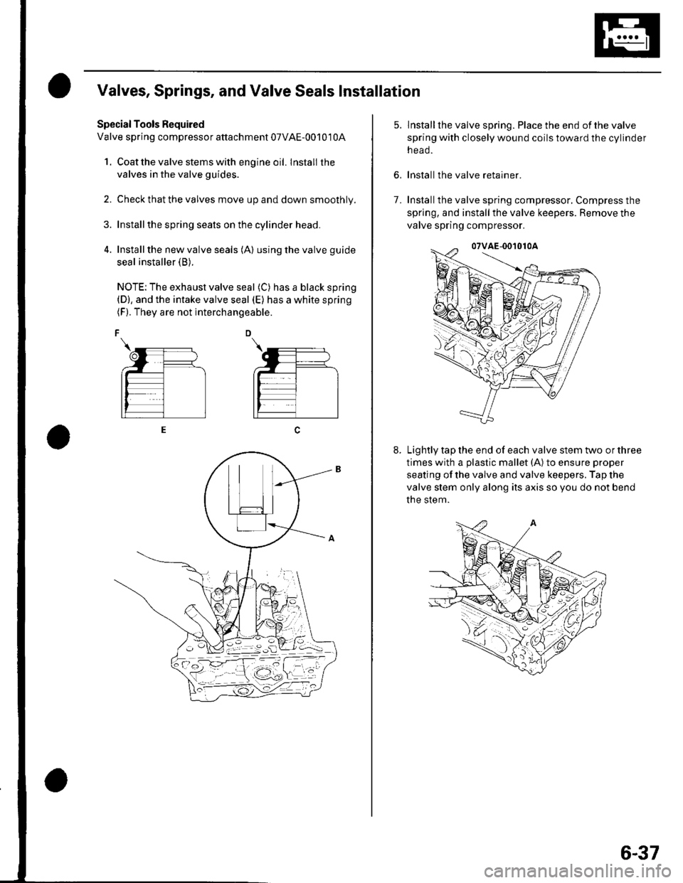
Valve spring compressor attachment 07VAE-00101 0A
1. Coat the valve stems with engine oil. lnstall the
valves in the valve guides.
2. Check that the valves move up and down smoothly.
Installthe spring seats on the cylinder head.
Install the new valve seals (A) using the valve guide
seal installer (B).
NOTE: The exhaust valve seal (C) has a black spring(D), and the intake valve seal (E) has a white spring(F). They are not interchangeable.
6.
lnstallthe valve spring. Place the end ofthe valve
spring with closely wound coils toward the cylinder
n eao.
Install the valve retainer.
Installthe valve spring compressor, Compress the
spring, and install the valve keepers. Remove the
valve spring compressor.
Lightly tap the end of each valve stem two or three
times with a plastic mallet (A) to ensure proper
seating of the valve and valve keepers. Tap the
valve stem only along its axis so you do not bend
the stem.
7.
6-37
Page 172 of 1139
Engine Lubrication
Engine Oil Filter Replacement
Special Tool Fequired
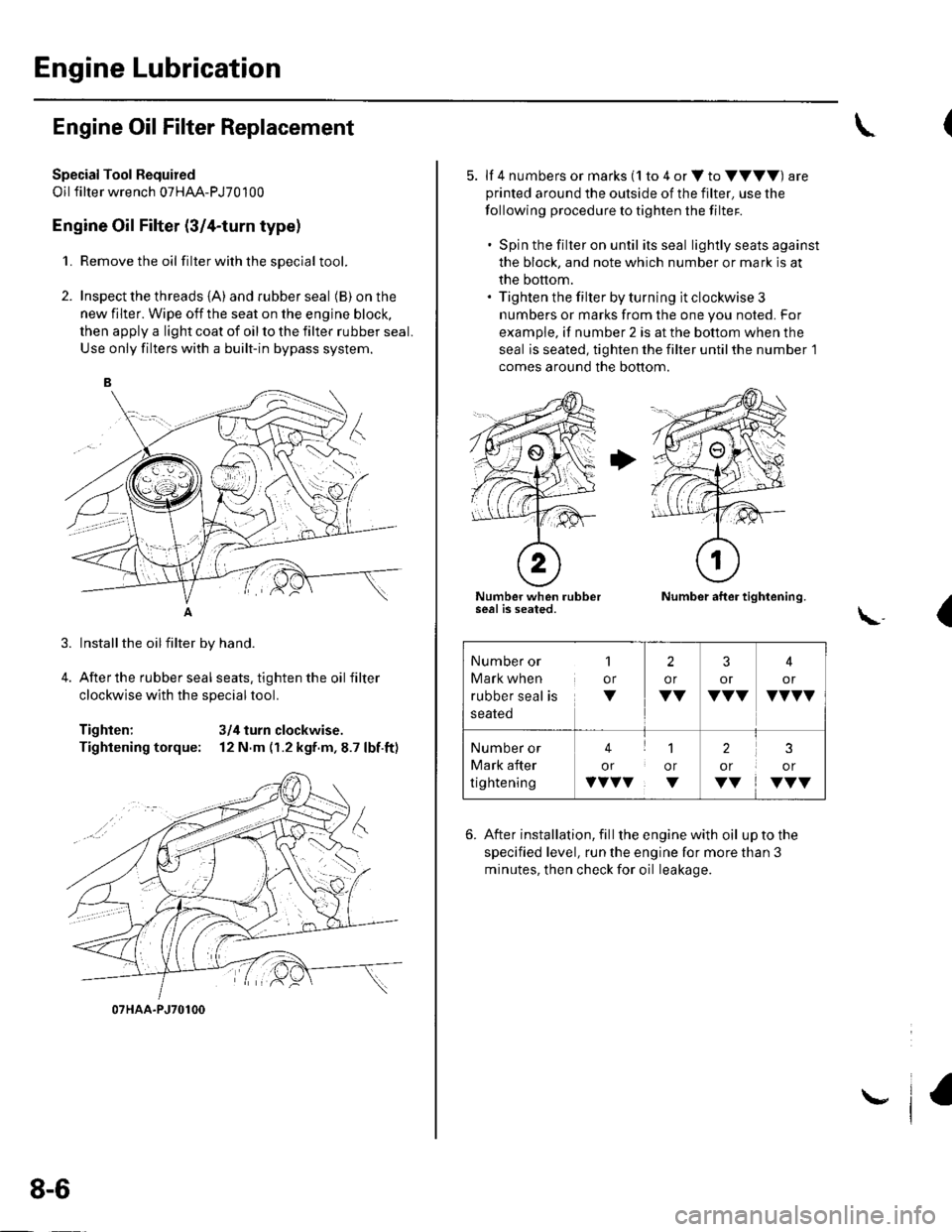
Oil filter wrench 07HAA-PJ70100
Engine Oil Filter (3/4-turn type)
1. Remove the oil filterwiththesDecial tool.
2. Inspect the threads {A) and rubber seal (B) on the
new filter. Wipe off the seat on the engine block,
then apply a light coat of oil to the filter rubber seal.
Use only filters with a built-in bypass system.
Installthe oilfilter by hand.
After the rubber seal seats, tighten the oil filter
clockwise with the special tool.
Tighten: 3/4 turn clockwise.
Tightening torque: 12 N.m (r.2 kgf.m,8.7 lbf.ft)
07HAA-PJ70100
8-6
\,
5. lf 4 numbers or marks (1 to 4 or V to VVVV) are
printed around the outside of the filter, use the
following procedure to tighten the filter.
. Spin the filter on until its seal lightly seats against
the block, and note which number or mark is at
the bottom.. Tighten the filter by turning it clockwise 3
numbers or marks from the one you noted. For
example, if number 2 is at the bottom when the
seal is seated, tighten the filter until the number 1
comes around the bottom.
Number when rubberseal is seated.Number after tightening.
(\..
6. After installation, fill the enginewith oil uptothe
specified level, run the engine for more than 3
minutes, then check for oil leakage.
Number or
Mark when
rubber seal is
1
or
V
2
or
VV
3
or
VVV
4
or
VVVV
Number or
Mark after
tightening
41
or or
vvvv. v
2
or
VV
3
or
VVV
Page 299 of 1139
PGM-FI System
I
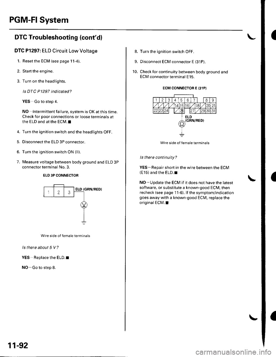
a
DTC Troubleshooting (cont'dl
DTC Pl297: ELD Circuit Low Voltage
1. Reset the ECM {see page 11-4).
2. Start the engine.
3. Turn on the headlights.
ls DTC P1297 indicated?
YES Go to step 4.
NO Intermittent failure, system is OK at this time.
Check for poor connections or loose terminals at
the ELD and at the ECM.I
4. Turn the ignition switch and the headlights OFF.
5. Disconnectthe ELD 3P connector.
6. Turn the ignition switch ON {ll).
7. Measure voltage between body ground and ELD 3P
connector terminal No. 3.
ELO 3P CONNECTOB
{GRN/REDI
Wire side of female terminals
ls there about 5 V?
YES Replace the ELD. t
NO-Go to step 8.
Z3ELD
11-92
8. Turn the ignition switch OFF.
9. Disconnect ECM connector E {31P).
10. Check for continuity between body ground and
ECM connector terminal E15.
ECM CONNECTOR E 131PI
I l2l3456178I
totd/ 12021,2 2al2/tA31
ELD(GRN/RED}7\'
Wire side of female terminals
ls there continuity?
YES-Repair short in the wire between the ECM(E 15) and the ELD. r
NO- U pdate the ECM if it does not have the latest
software, or substitute a known-good ECM, then
recheck (see page 1 1-6). lf the symptom/indication
goes away with a known-good ECM, replace the
original ECM.I
Page 300 of 1139
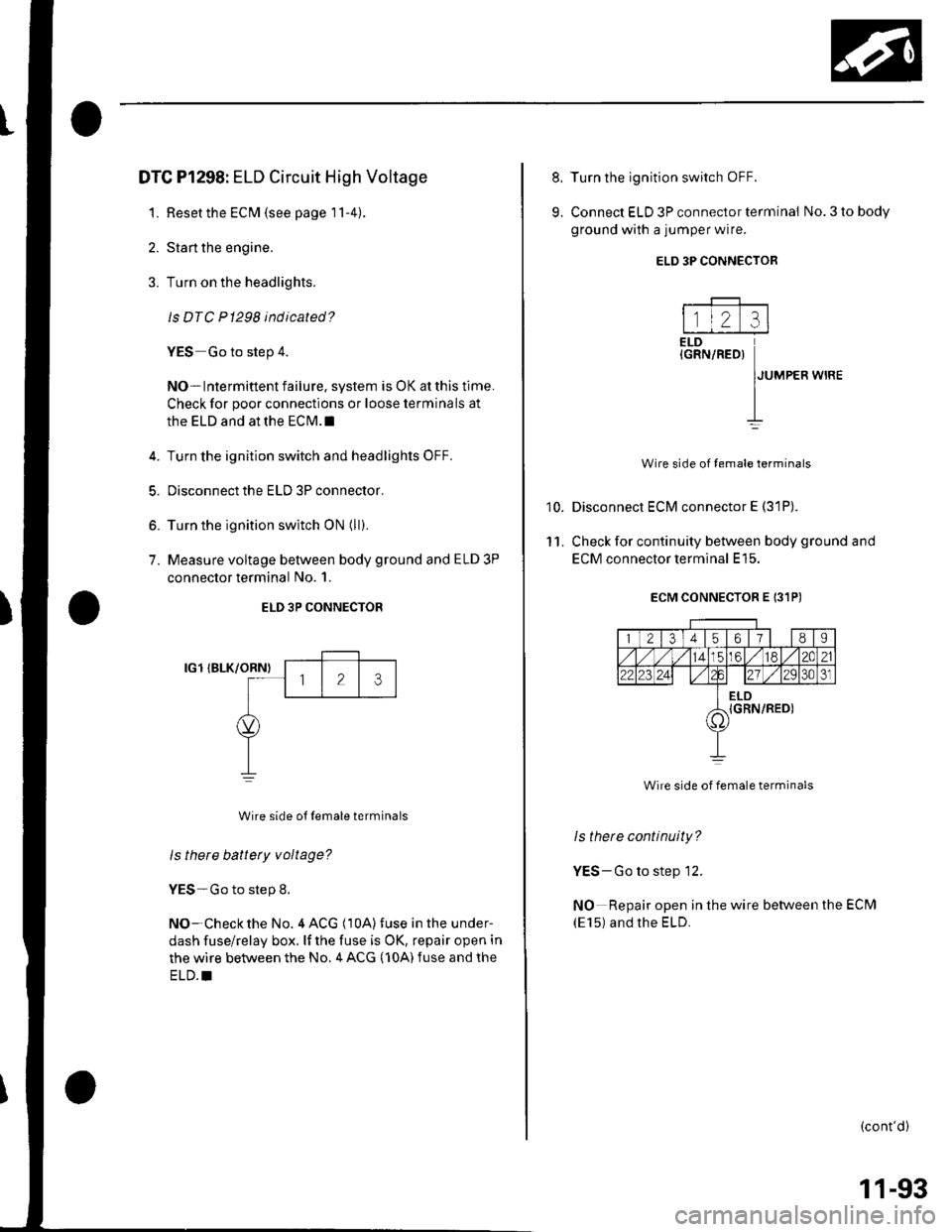
DTC Pl298: ELD Circuit High Voltage
1. Resetthe ECM (see page 11-4)
2. Stan the engine.
3. Turn on the headlights.
ls DTC P1298 indicated?
YES-Go to step 4.
NO- Intermittent failure. system is OK at this time.
Check for poor connections or loose terminals at
the ELD and at the ECM.I
4. Turn the ignition switch and headlights OFF.
5. Disconnectthe ELD 3P connector.
6. Turn the ignition switch ON (ll).
7. Measure voltage between body ground and ELD 3P
connector terminal No. 1.
ELD 3P CONNECTOR
IG1 IBLK/ORNI
Wire side ot {emale terminals
ls there battery voltage?
YES-Go to step 8.
NO-Checkthe No. 4 ACG (10A)fuse in the under-
dash fuse/relay box. lf the fuse is OK, repair open in
the wire between the No. 4 ACG (10A) fuse and the
ELD.I
8.
9.
10.
11.
Turn the ignition switch OFF.
Connect ELD 3P connector terminal No. 3 to body
ground with a jumper wire.
Disconnect ECM connector E (31P).
Check for continuity between body ground and
ECM connector terminal E15.
ECM CONNECTOR E 131PI
1 21345ot/II
14LC6l/ 182C21
22123 2421 ./2Q30J
ELDIGRN/RED)i1'
Wire side of female terminals
Is thete continuity?
YES-Go to step 12.
NO Repair open in the wire between the ECM
(E15) and the ELD.
(cont'd)
ELD 3P CONNECTOR
---F-------
l1l2 :rlELD(GRN/RED)
IJUMPER wrRE
II
Wire side of temale terminals
11-93