clock HONDA CIVIC 2002 7.G Owner's Manual
[x] Cancel search | Manufacturer: HONDA, Model Year: 2002, Model line: CIVIC, Model: HONDA CIVIC 2002 7.GPages: 1139, PDF Size: 28.19 MB
Page 616 of 1139
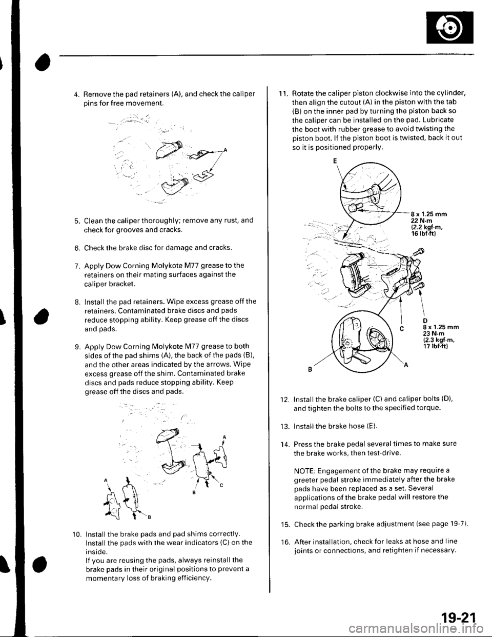
4. Remove the pad retainers (A). and check the caliper
pins for free movement.
:.i _ _l
7.
8.
5. Clean the caliper thoroughly; remove any rust. and
check for grooves and cracks.
6, Check the brake disc for damage and cracks.
Apply Dow Corning Molykote M77 grease to the
retainers on their mating surfaces against the
caliper bracket,
Installthe pad retainers. Wipe excess grease offthe
retainers. Contaminated brake discs and pads
reduce stopping ability. Keep grease off the discs
and pads.
Apply Dow Corning Molykote lvl77 grease to both
sides of the pad shims {A), the back of the pads (B),
and the other areas indicated by the arrows. Wipe
excess grease off the shim. Contaminated brake
discs and pads reduce stopping ability. Keep
grease off the discs and pads.
9.
..-.
10. Installthe brake pads and pad shims correctly.
Installthe pads wirh the wear indicators {C) on the
inside.
lf you are reusing the pads, always reinstall the
brake pads in their original positions to prevent a
momentary loss of braking efficiency.
11. Rotate the caliper piston clockwise into the cylinder,
then align the cutout (A) in the piston with the tab
{B) on the inner pad by turning the piston back so
the caliper can be installed on the pad. Lubricate
the boot with rubber grease to avoid twisting the
Diston boot. lf the piston boot is twisted, back it out
so it is positioned properly.
8 x 1.25 mm22 N.ml2.2 kgt m,16 rbl.ttl
.ar
D8 x 1.25 mm23Nm{2.3 kgf.m,17 rbf.ft)
13.
14.
Installthe brake caliper (C) and caliper bolts (D).
and tighten the bolts to the specified torque.
Installthe brake hose (E).
Press the brake pedal several times to make sure
the brake works, then test-drive.
NOTE: Engagement of the brake may require a
greeter pedal stroke immediately after the brake
pads have been replaced as a set. Several
applications of the brake pedal will restore the
normal pedal stroke,
15. Check the parking brake adjustment {see page 19-7).
16. After installation, check for leaks at hose and line
joints or connections, and retighten if necessarY.
19-21
Page 716 of 1139
Dashboard
Dashboard Center Panel Removal/lnstallation
NOTE:. Put on gloves to protect your hands.. When prying with a flat-tip screwdriver, wrap it with
protective tape, and apply protective tape around the
related parts, to prevent damage.. Take care not to scratch the dashboard and related
parts.
1. Make sure you have the anti-theft code for the radio,
the write down the frequencies for the preset
buttons.
Remove these items:
. Driver's dashboard lower cover (see page 20-59)
. Passenger's dashboard lower cover (see page
20-63).. Glove box (see page 20-63).. Shift lever trim {see page 20-61).
From the glove box and driver's dashboard Iower
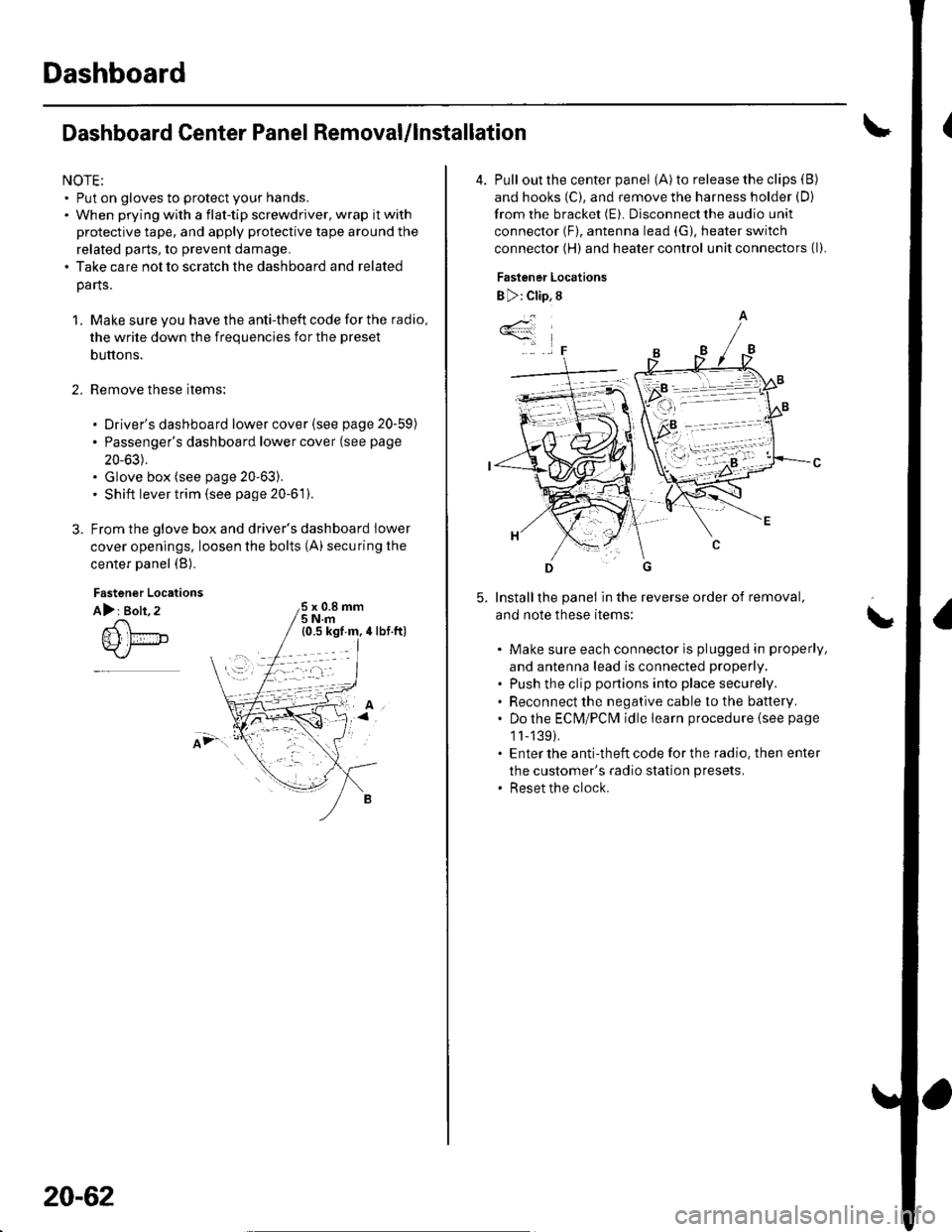
cover openings, loosen the bolts (A) securing the
center panel (B).
2.
Fastener Locations
A): Bolt, 2x 0.8 mm5Nm
;.'
20-62
4. Pull out the center panel (A) to release the clips (B)
and hooks (C), and remove the harness holder (D)
from the bracket (E). Disconnect the audio unit
connector (F), antenna lead (G), heater switch
connector (H) and heater control unit connectors (l).
Fastener Locations
B ): Clip, 8
Installthe panel in the reverse order of removal,
and note these items:
Make sure each connector is plugged in properly,
and antenna lead is connected properly.
Push the clip portions into place securely.
Reconnect the negative cable to the battery.
Do the ECN4/PCt\4 idle learn procedure {see page
1l-139).
Enter the anti-theft code for the radio. then enter
the customer's radio station presets.
Reset the clock.
*4
,F
\
Page 722 of 1139
Dashboard
Dashboard Removal/lnstallation
(cont'd)
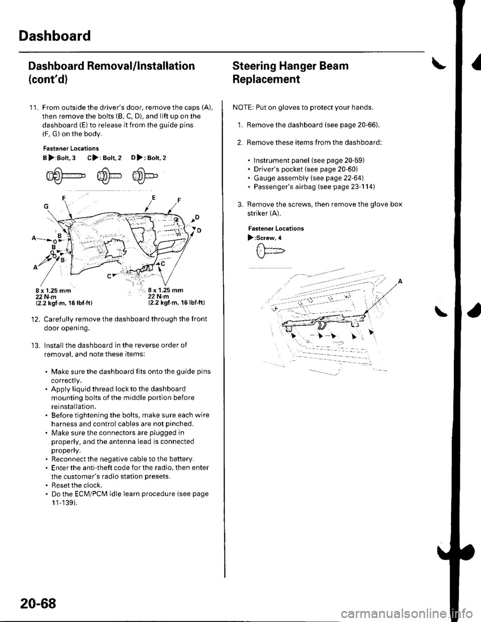
11. From outside the driver's door, remove the caps (A),
then remove the bolts (8, C, D), and lift up on the
dashboard (E) to release it from the guide pins
(F. G) on the body.
Fastener Locations
B>rBolt.3 C>: Bolt,2 D>: Bolt,2
m6[-,,,,",",,-,F6't---'' ffi'!--v{/- Kr* w-
B
$7:
^/761:
/,-,. r:; 8 x 1.25 mm22Nm(2.2 kgf.m, 16lbf.ft)
13.
{2.2 kgf m, 16lbf.ftl
Carefully remove the dashboard through the front
door opening.
lnstall the dashboard in the reverse order of
removal, and note these items:
. Make sure the dashboard fits onto the guide pins
correctly.. Apply liquid thread lock to the dashboard
mounting bolts of the middle portion before
reinstallation.. Before tightening the bolts, make sure each wire
harness and control cables are not pinched.
. Make sure the connectors are plugged in
properly, and the antenna lead is connected
propeny.. Reconnect the negative cable to the battery.. Enter the anti-theft code for the radio, then enter
the customer's radio station presets.
. Reset the clock.. Do the ECM/PCM idle learn procedure isee page
1 '1-139).
20-68
Steering Hanger Beam
Replacement
NOTE: Put on gloves to protect your hands.
1, Remove the dashboard (see page 20-66).
2. Remove these items from the dashboard:
. lnstrument panel (see page 20-59). Driver's pocket (see page 20-60). Gauge assembly (see page 22-64). Passenger's airbag (see page 23-'l 14)
Remove the screws, then remove the glove box
striker (A).
Fastenea Locations
):Screw,4
\
Page 726 of 1139
Seats
Front Seat Removal/lnstallation (cont'dl
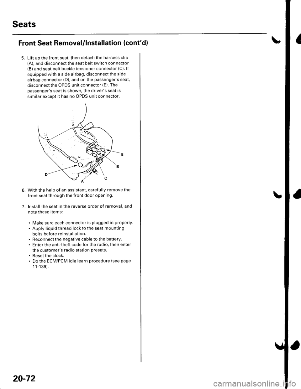
Lift up the front seat, then detach the harness clip(A). and disconnect the seat belt switch connector(B) and seat belt buckle tensioner connector (C). lf
equipped with a side airbag, disconnect the side
airbag connector (D), and on the passenger's seat,
disconnect the OPDS unit connector (E). The
passenger's seat is shown, the driver's seat is
similar except it has no OPDS unit connector.
With the help of an assistant, carefully remove the
front seat th rough the front door opening.
Installthe seat in the reverse order of removal, and
note these rtems:
. l\4ake sure each connector is plugged in properly.
. Apply liquid thread lock to the seat mounting
bolts before reinstallatlon.. Reconnect the negative cable to the battery.. Enter the anti-theft code for the radio, then enter
the customer's radio station presets.
. Reset the clock.. Do the ECM/PCM idle learn procedure (see page
1 1-139).
6.
7.
20-72
Page 912 of 1139
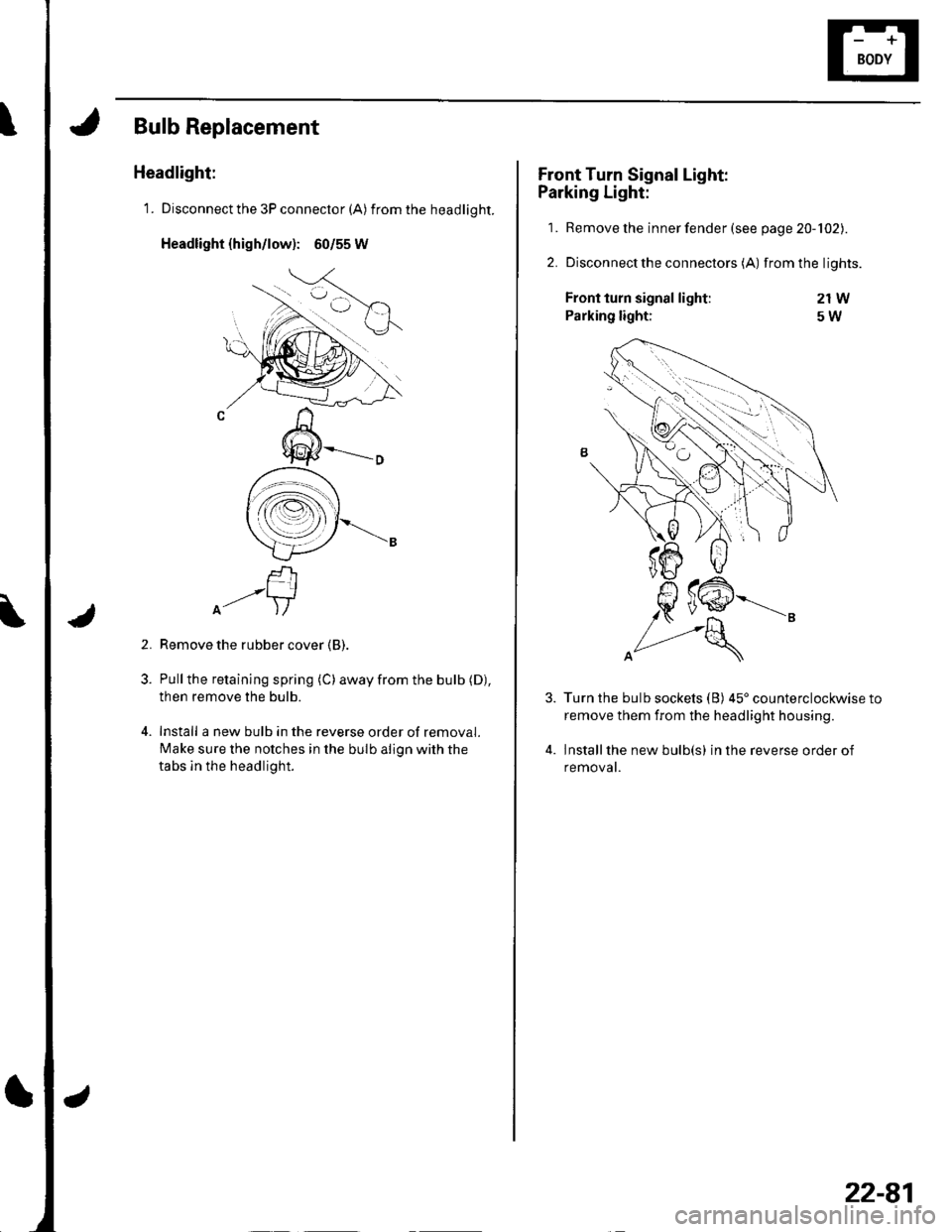
Bulb Replacement
Headlight:
1. Disconnect the 3P connector (A) from the headlight.
Headlight {high/low): 60/55 W
f-rI-'-+lA- )/
Remove the rubber cover (B).
Pull the retaining spring (C) away from the bulb (D),
then remove the bulb.
Install a new bulb in the reverse order of removal.
Make sure the notches in the bulb align with the
tabs ln the headlight.
2.
Front Turn Signal Light:
Parking Light:
1. Remove the inner fender (see page 20-102).
2. Disconnectthe connectors (A) from the lights.
21W
5W
4.
Front turn signal light:
Parking light:
Turn the bulb sockets (B) 45'counterclockwise to
remove them from the headlight housing.
Installthe new bulb(s) in the reverse order of
removat.
22-81
Page 913 of 1139
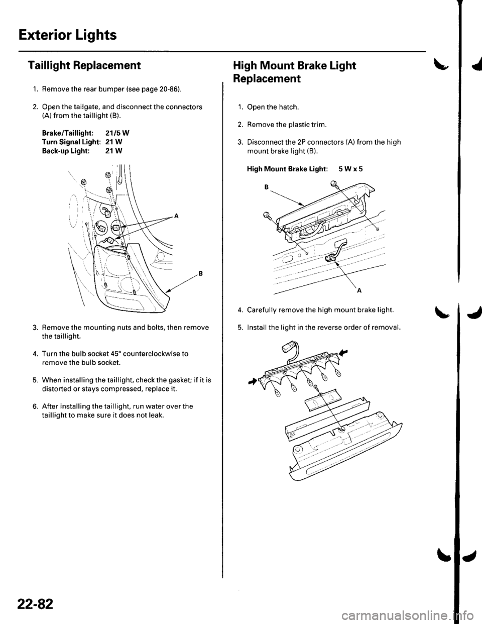
Exterior Lights
1.
2.
Taillight Replacement
Remove the rear bumper (see page 20-86).
Open the tailgate, and disconnect the connectors(A) from the taillight (B).
Brako/Taillight; 2115W
Turn Signal Light: 21 W
Back-up Light: 21W
Remove the mounting nuts and bolts, then remove
the taillight.
Turn the bulb socket 45' counterclockwise to
remove the bulb socket.
When installing the taillight. check the gasket; if it is
distorted or stays compressed, replace it.
After installing the taillight. run water over the
taillight to make sure it does not leak.
=\
ili--- _ \
rB , \.
---'a t
\
22-82
High Mount Brake Light
Replacement
1. Open the hatch.
2. Remove the plastic trim.
3. Disconnectthe 2P connectors (A)from the high
mount brake light (B).
High Mounl Brake Light: 5 W x 5
Carefully remove the high mount brake light.
lnstall the light in the reverse order of removal.5.
'
Page 914 of 1139
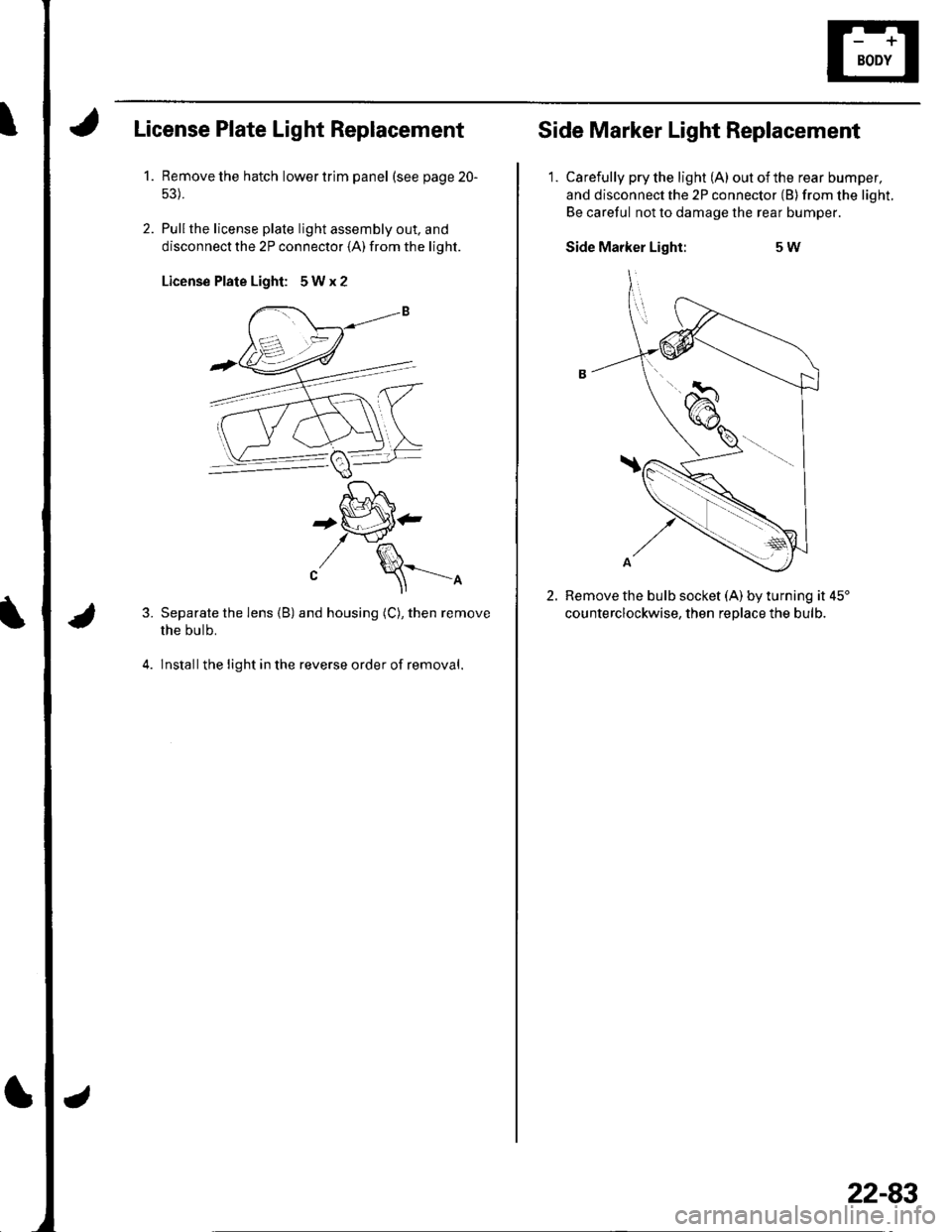
License Plate Light Replacement
1.Remove the hatch lower trim panel (see page 20-
Pullthe license plale light assembly out. and
disconnect the 2P connector (A) from the light.
License Plate Light: 5Wx2
3.
4.
'[-J^,^f , t lo \
+tiP'-t \-J'fl^
"/ \==-^
Separate the lens (B) and housing (C), then remove
the bulb.
lnstallthe light in the reverse order of removal.
Side Marker Light Replacement
1. Carefully pry the light (A) outofthe rear bumper,
and disconnect the 2P connector (B) from the light.
Be careful not to damage the rear bumper.
Side Marker Light:5W
2.Remove the bulb socket (A) by turning it 45'
counterclockwise. then reolace the bulb.
22-83
Page 1013 of 1139
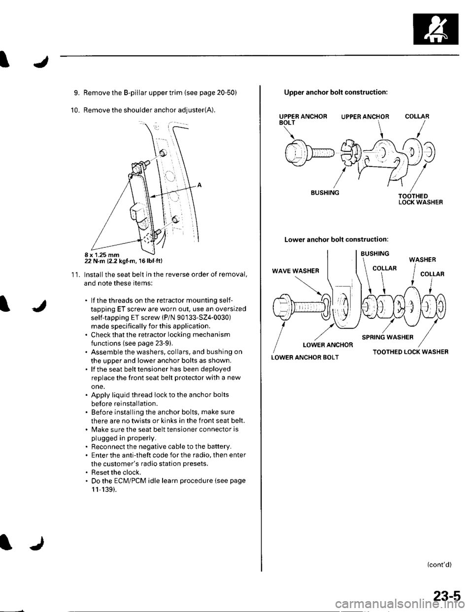
9.
10.
Remove the B-pillar upper trim {see page 20-50)
Remove the shoulder anchor adjuster{A).
22 N.m (2.2 kgf.m, 16lbf.ftl
Installthe seat belt in the reverse order of removal,
and note these items:
. lf thethreads on the retractor mounting self-
tapping ET screw are worn out, use an oversized
self-tapping ET screw (P/N 90133-SZ4-0030)
made specifically for this application.. Check that the retractor locking mechanism
functions (see page 23-9).. Assemble the washers, collars, and bushing on
the upper and lower anchor bolts as shown.. lf the seat belt tensioner has been deployed
replace the front seat belt protector with a new
one.. Apply liquid thread lock to the anchor bolts
before reinstallation.. Before installing the anchor bolts, make sure
there are no twists or kinks in the front seat belt.. Make sure the seat belt tensioner connector is
plugged in properly.
. Reconnect the negative cable to the battery.. Enter the anti-theft code for the radio, then enter
the customer's radio station presets.
. Reset the clock.. Do the ECM/PCM idle learn procedure {see page
11,139).
11.
8 x 1.25 mm
UPPER ANCHORBOLT
BUSHING
Upper anchor bolt construction:
UPPER ANCHOR
Lower anchor bolt construction:
COLLAR
TOOTHEDLOCK WASHER
LOWER ANCHOR BOLTTOOTHED LOCK WASHER
{cont'd)
WASHER
23-5
Page 1014 of 1139
Seat Belts
Front Seat Belt Replacement (cont'd)
Seat Belt Buckle
1. Make sure you have the anti-theft code for the radio,
then write down the frequencies for the preset
buttons.
2. Disconnect the negative cable from the battery ,and wait at least 3 minutes before beginning work.
3. Remove the front seat (see page 20-7'1).
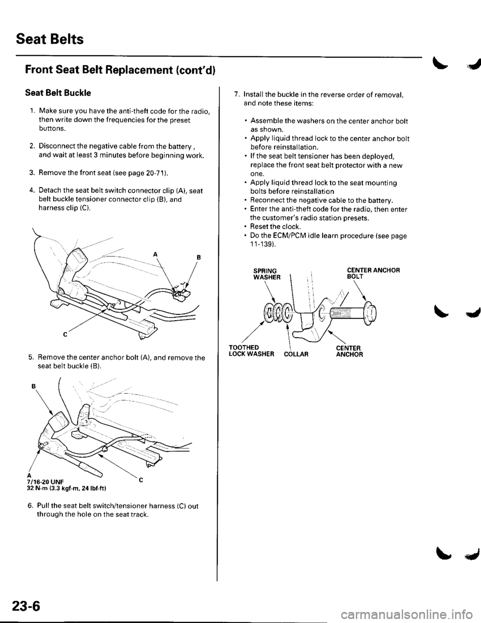
4. Detach the seat belt switch connector clip (A), seat
belt buckle tensioner connector clip (B), and
harness clip (C).
5. Remove the center anchor bolt (A), and remove the
seat belt buckle {B).
7/16-20 UNF32 N m {3.3 kgf m,24lbf.ft)
6. Pullthe seat belt switch/tensioner harness (C) out
through the hole on the seat track.
. -.. :.a--
23-6
7. Installthe buckle in the reverse order of removal,
and note these items:
. Assemble the washers on the center anchor bolt
as shown.. Apply liquid thread lock to the center anchor bolt
before reinstallation.. lf the seat belt tensioner has been deployed,
replace the front seat belt protector with a new
one.. Apply liquid thread lock to the seat mounting
bolts before reinstallation. Reconnect the negative cable to the battery.. Enter the anti-theft code for the radio, then enter
the customer's radio station presets.. Reset the clock.. Do the ECMiPCM idle learn procedure (see page
1 1_139).
COLLAR
Page 1021 of 1139
sRs
Precautions and Procedures
General Precautions
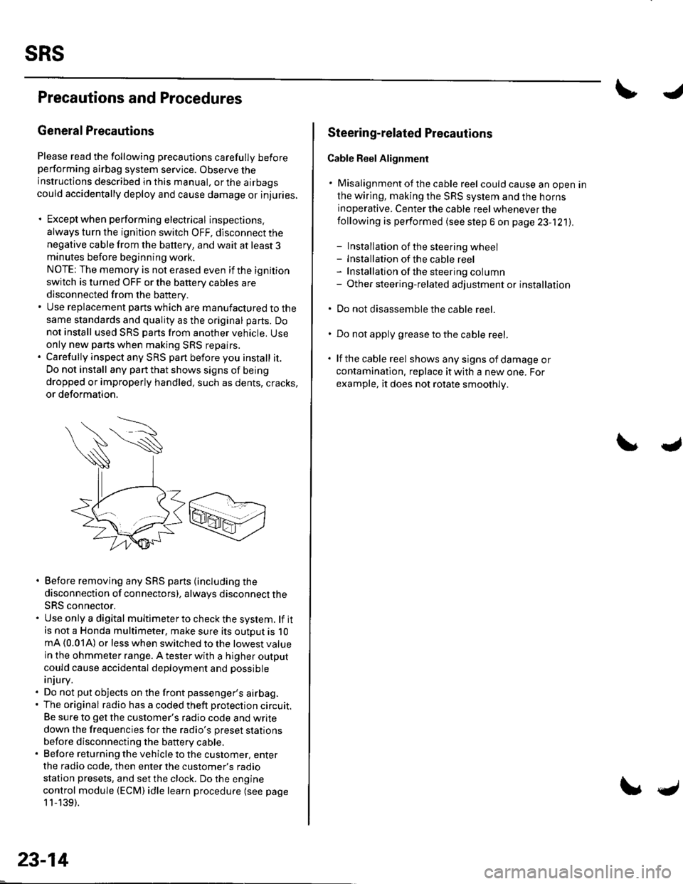
Please read the following precautions carefully beforeperforming airbag system service. Observe theinstructions described in this manual. or the airbags
could accidentally deploy and cause damage or injuries.
. Except when performing electrical inspections.
always turn the ignition switch OFF, disconnect the
negative cable from the battery, and wait at least 3minutes before beginning work.
NOTE: The memory is not erased even if the ignition
switch is turned OFF or the battery cables are
disconnected from the battery.. Use replacement pans which are manufactured to the
same standards and quality as the original parts. Do
not install used SRS parts from another vehicle. Useonly new pans when making SRS repairs.. Carefully inspect any SRS part before you install it.
Do not install any part that shows signs of being
dropped or improperly handled, such as dents, cracks,
or deformation.
. Before removing any SRS parts (including the
disconnection of connectors), always disconnect the
SRS connector.. Use only a digital multimeter to check the system. lf itis not a Honda multimeter, make sure its outout is 10mA (0.01A) or less when switched to the lowest value
in the ohmmeter range. A tester with a higher output
could cause accidental deployment and possible
injury.. Do not put objects on the front passenger's airbag.. The original radio has a coded theft protection circuit.
Be sure to get the customer's radio code and write
down the frequencies for the radio's preset stations
before disconnecting the battery cable.. Before returning the vehicle to the customer, enter
the radio code. then enter the customer's radio
station presets, and set the clock. Do the engine
control module (ECM) idle learn procedure (see page
11-139).
23-14
c
Steering-related Plecautions
Cable Reel Alignment
. Misalignment of the cable reel could cause an open in
the wiring, making the SRS system and the horns
inoperative. Center the cable reel whenever the
following is performed (see step 6 on page 23-121).
- Installation of the steering wheel- Installation of the cable reel- Installation ofthe steering column- Other steering-related adjustment or installation
. Do not disassemble the cable reel.
. Do not apply grease to the cable reel.
. lf the cable reel shows any signs of damage or
contamination. replace it with a new one. For
example, it does not rotate smoothly.