shift HONDA CIVIC 2002 7.G Owner's Manual
[x] Cancel search | Manufacturer: HONDA, Model Year: 2002, Model line: CIVIC, Model: HONDA CIVIC 2002 7.GPages: 1139, PDF Size: 28.19 MB
Page 716 of 1139
Dashboard
Dashboard Center Panel Removal/lnstallation
NOTE:. Put on gloves to protect your hands.. When prying with a flat-tip screwdriver, wrap it with
protective tape, and apply protective tape around the
related parts, to prevent damage.. Take care not to scratch the dashboard and related
parts.
1. Make sure you have the anti-theft code for the radio,
the write down the frequencies for the preset
buttons.
Remove these items:
. Driver's dashboard lower cover (see page 20-59)
. Passenger's dashboard lower cover (see page
20-63).. Glove box (see page 20-63).. Shift lever trim {see page 20-61).
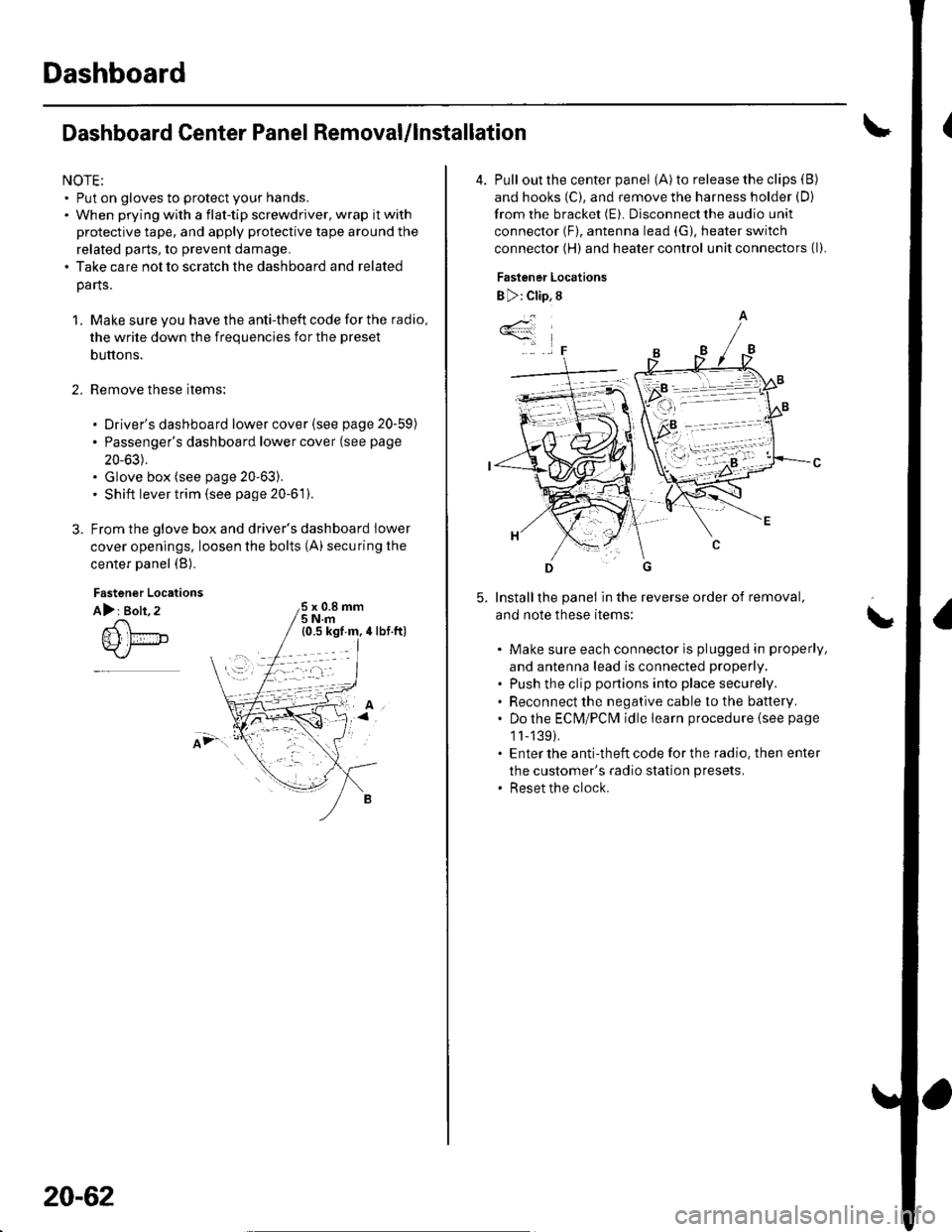
From the glove box and driver's dashboard Iower
cover openings, loosen the bolts (A) securing the
center panel (B).
2.
Fastener Locations
A): Bolt, 2x 0.8 mm5Nm
;.'
20-62
4. Pull out the center panel (A) to release the clips (B)
and hooks (C), and remove the harness holder (D)
from the bracket (E). Disconnect the audio unit
connector (F), antenna lead (G), heater switch
connector (H) and heater control unit connectors (l).
Fastener Locations
B ): Clip, 8
Installthe panel in the reverse order of removal,
and note these items:
Make sure each connector is plugged in properly,
and antenna lead is connected properly.
Push the clip portions into place securely.
Reconnect the negative cable to the battery.
Do the ECN4/PCt\4 idle learn procedure {see page
1l-139).
Enter the anti-theft code for the radio. then enter
the customer's radio station presets.
Reset the clock.
*4
,F
\
Page 720 of 1139
Dashboard
Dashboard Removal/lnstallation
SRS components are located in this area. Review the
SRS component locations (see page 23-13) and the
precautions and procedures (see page 23-14) in the SRS
section before performing repairs or service.
NOTE:. When prying with a flat-tip screwdriver, wrap it with
protective tape, and apply protective tape around the
related parts to prevent damage.. Have an assistant help you when removing and
installing the dashboa rd.. Take care not to scratch the dashboard, body, and
other related parts.
. Put on gloves to protect your hands.
1. Make sure you have the anti-theft code for the radio,
then write down the frequencies for the preset
buttons.
Disconnect the negative cable from the battery, and
wait at least three minutes before beginning work.
Remove these items:
. Driver's dashboard lower cover (see page 20-59). Driver's dashboard under cover (see page 20-60). Passenger's dashboard lower cover (see page
20-63). Glove box (see page 20-63). Consoles, front and rear (see page 20-57). Shift lever trim {see page 20-61). Center panel (see page 20-62). Kick panels, both sides (see page 20-50). A-pillar trim. both sides (see page 20-50). Steering column (see page 17-9)
20-66
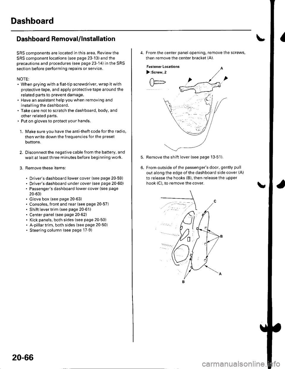
4. From the center panel opening, remove the screws,
then remove the center bracket (A).
Fastener Locations
):Screw,2
Remove the sh ift lever (see page 13-51).
From outside of the passenger's door, gently pull
out along the edge of the dashboard side cover (A)
to release the hooks (B), then release the upper
hook (C), to remove the cover.
Page 1033 of 1139
sRs
General Troubleshooting Information (cont'dl
Erasing the DTG Memory
Specisl Tool Required
SCS service connector 07PAz-0010100
To erase the DTC(S)from the SRS unit, use a Honda
PGM Tester {see lhe Honda PGfM Tester SRS Vehicle
System Supplement) or the following procedure.
1. Make sure the ignition switch is OFF.
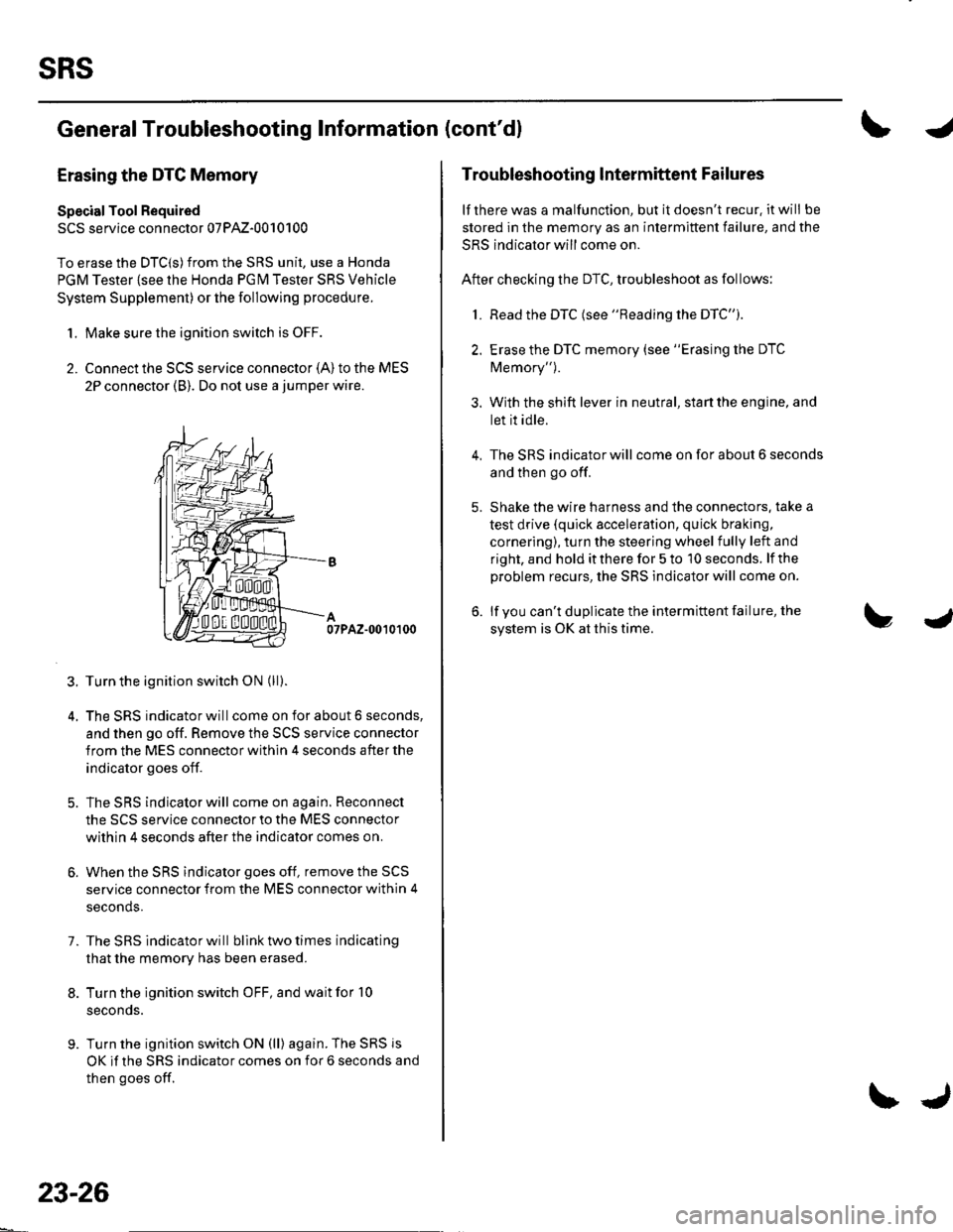
2. Connect the SCS service connector {A) to the MES
2P connector (B). Do not use a jumper wire.
07PAZ-0010100
3. Turn the ignition switch ON (ll).
4. The SRS indicator will come on for about 6 seconds,
and then go off. Remove the SCS service connector
from the MES connector within 4 seconds after the
indicator goes off.
5. The SRS indicator will come on again. Reconnect
the SCS service connector to the MES connector
within 4 seconds after the indicator comes on.
6. When the SRS indicator goes off, remove the SCS
service connector from the MES connector within 4
seconds.
7. The SRS indicator will bllnk two times indicating
that the memory has been erased.
8. Turn the ignition switch OFF, and wait for '10
seconds.
9. Turn the ignition switch ON (ll) again. The SRS js
OK if the SRS indicator comes on for 6 seconds and
then goes off.
23-26
\J
Troubleshooting lntermittent Failures
lf there was a malfunction, but it doesn't recur. it will be
stored in the memory as an intermittent failure, and the
SRS indicator will come on.
After checking the DTC, troubleshoot as follows:
1. Read the DTC (see "Reading the DTC").
2. Erase the DTC memory (see "Erasing the DTC
Memory").
3. With the shift lever in neutral, start the engine, and
let it idle.
The SRS indicator will come on for about 6 seconds
and then go off.
Shake the wire harness and the connectors. take a
test drive (quick acceleration, quick braking,
cornering), turn the steering wheel fully left and
right, and hold it there for 5 to '10 seconds. lf the
problem recurs, the SRS indicator will come on.
lf you can't duplicate the intermittent failure, the
system is OK at this time.
4.
Page 1137 of 1139
)
Low Fuel lndicatorTest.....................11-158Moonroof Drain Channel SliderReplacement......................................... 20'44
Moonroof FrameRep1acement,,,,,,,,,,.,.,.,.,.,.,.,,,,,,............ 20 42
MoonroolGlassAdiustment ........................................... 20-37Rep1acement......................................... 20 37
Moonroot Limit SwitchAdjustment ........................................-.- 20 46Test ...................................................... 22 113
Moonrool MotorReplacement....-.................................... 2D-41
Oil Pressure SwitchTest ................-.-........-................................ 8-4Replacement.........-................................. 8-16
Oil Pump, EngineOverhau1 ................................................... 8-8
Oil, EngineReplacement...-................-.-...................... 8-5
OPDS UnitReplacement....................................... 23- 124
Outside Mirror HoldersBeplacement......................................... 20-15
Outside Power Mirror ActuatorsTest ...................................................... 22-117Bepf acement..-.................................... 22-1 14
Outside Power Mirror SwitchTest ..-................................................... 22-111
Outsid€ Power MirrorsReplacement............................ ... .. . . . 20-15Component Location lndex .............. 22- 114Circuit Diagram .................................. 22-115Test -..................................................... 22-116
Lower ArmsRemoval/1nsta11ation............................ 18 19
Lubrication SystemComponent Location Index..................... 8-3Test............................................................ 8 4
M
M/TAssemblyRemoval.......... 13-4 Test...................... 22-1 12lnstallation............. 13-8
.........21,35
Disassembly ......................................... 13-14Resassembly .. ... ................. 13-46
M/TChange Leverlnspection ............................................. 13-19Disassembly 8eassemb1y ................... 13-20
M/T Countershaft AssemblyInspection ....................................... 13 31, 33Disassemb1y ......................................... 13-32Resassemb|y ........................................ 13-34
M/T DifferentialComponentLocation Index................. 13-52Adiuslment ........................................... 13-56
M/T Maifthaft Assembly1nspection ... ................................... 13-23, 26Disassembly ......................................... 13 25Resassembly ........................................ 13 28Adjustment ........................................... 13-43
M/T Reverse Shift ForkInspection .................... ........................ l3 19
M/T Shift LevelReplacement......................................... 13-51
Mainshaft BearingsReplacement....,.................................... 13 41
MairtenancelSee section 3)
MILHow to Informatron ............................. 1 1.46
MIL CircuitTroubleshooting .......... .- . . . . ......... 11 97
MirrorsComponentLocation Index................. 20'14
Mode Control MotorReplacement
Moonrool SunshadeRep1acement....................... . . ............. 20 40
Moonroof SwitchTesVRep1acement .............................. 22- l 12
Mooniool Wind Def lectorReplacement.......................-................. 20-38
Moonroof/SunroofComponent Location Index ... 20-35, 22-108Test ........................................................ 20-48Cf rcuit Diagram .................................. 22- 109
MTFInspection/Rep1acement. .......... ........... 13-3
Muhiplex Control SystemComponentLocation lndex ..............22 168Circuit Diagram .................................. 22-1690escription ......................................... 22-17 1Troubleshooting ................................ 22-17 2
Muliiplex Control Unit, Under-dashInput TestEntry Light Control Sysiem ............. 22-92Keyless Entry/Security AlarmSystern .-....................................... 22-155MultiplexControl System .............22 115Wiper/Washer................................. 22'1 41
NoiseTest,,Reduction Condenser
Parking ErakeInspection Adjustment ........... .............. 19-7
Parking Brake CableRep1acement......................................... 19-26
Parking Erake Switch
P
l
Test ...................... 19-10
Test............................... . ...........2135
Moonroof Auto Stop SwitchosTest ...................................................... 22'113
Moon.oot Control Unillnput Test ............................................ 22-110
Moonroof Drein ChannelBeplacement ... . ....... ......................... 20 39
Oil Filte]Replacement............................................. 8-6
Oil Filter Feed PipeReplacement............... . ..-,...,.,,,,,,,,8-7
Oil PanRemoval .............,.,,,,,,,,,,,,.,.,,,.........-....... 7 1 1lnstallation .............................................. 7 -27
Passenger's TraVRemoval/lnstallation ............................ 20-65
PCV ValveBeplacement....................................... 1 1'169Test........................................... l1 169
Piston Rings8ep1acement................................-.-...-.- 7-21
PistonsReplacement...................-....................... 7-181nsta|1ation ...................................... ...1-23
Power R€layTest ...............-.-...................................... 22-51
Power Window Motor, Driver'stesl.....,,,, .,.,,,............
Power Window Motors, Passenger's
Power Window Switch, Masterlnput Test ..........-.........-....................... 22-126Tesr ....... . ............................................ 22 124Replacement....................................... 22-133
N
..............22 101
o
l' ,e
(cont'd)
Page 1138 of 1139
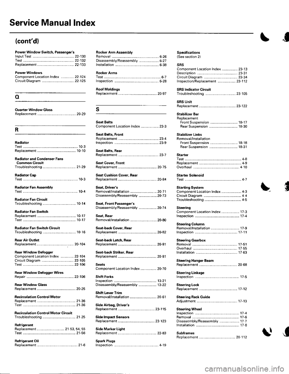
Service Manual lndex
(cont'dl
Power Window Switch, Passenger'slnput Test .............-......
Replacement...,-.-.-...,..
Radialor Cap
Rocker Arm AssemblyRemovalD;sassembly/Reassembly
Specifications6-26 (See section 2)22-13022 13222-133..................... 6-27
ComponentLocation Index ..............22 124Circuit Dia9ram .................. ............... 22 125
Ouaner Window Glass8ep1acement ......................................... 20-29
lnstallation6-38
Rocker ArmsTestInspecton6-28
Roof MoldingsReplacement
Seat BeltsComponent Location Index ................... 23-3
Seat 8ehs, FrontReplacementrnspec!on
sRsComponent Location Index ................. 23-13Description ....................................... 23-31Circuit D;agram ... .... ...........2334lnspection/Replacemenl ................... 23 1 126-7
SRS lndicator CircuilTroubleshooting
Startel
Stabilizer BarReplacementFront SuspensionRear Suspension
Stabilizer LinksRemoval/lnstallationFront SuspensionRear Suspension
23 105oSRS UnitReplacement..-.................................... 23-122s
R
1A-1718-30
18 1818-31RadiatorTest......23-9
23-1Replacement ...........
Radiator and Condenser FansCommon CircuitTroubleshooling......... ..... .........21 29
10-310-10Seat Behs, RearReplacement
Seat Cover, FrontReplacement
Seat Cushion Cover, R6ar10-3Replacement
ReplacementTest
Test
20-75
20-84
Overhaul
Starter SolenoidTest..-.-...4-7
Radiator Fan AssemblyTestSeat, Driver'sRemovaf/lnstaf lation ............................ 20 1 1Disassembly/Reassemb1y ................... 20-73
Sedt, Faont Passenger'sDisassembly/Reassemb1y ................... 20-74
Seat, RearRemoval/lnstallation ............................ 20-80
Seat-back Cover, Reer
Starting SystemComponent Location Index...............-..... 4-3CircuitDia9ram ........................................ 4 4
\'{........................ r0-4
Radiator Fan CircuitTroubleshooting
Radiator Fan SwhchReplacementTest
Radiator Fan Switch CircuitTroubleshooting
Rear Air OutletReplacement
Circuil DiagramTest
Rear Window D€rogger WiresRepair
RearWindow GlassReplacement
Troubleshooting10-14
10-1710-17
10 16
17 -3
11-4
17-9
SteeringComponent Location Index................-..Inspectaon ...................
Steering ColumnRemoval/lnstallationReplacementInspection11 11
17-5117 5517 63
20 68
Seat-back Latch, ReaI2Q-104Replacement
Seat-back Striker. RearReplacement
Steering GearboxRemovalOverhaulRear Window DefoggerComponentLocalion Index ..............22 104lnstallation
Steering Hanger BeamReplacement
Steering LinkageInspefiron
Steering LockReplacement
Steering Rack GuideAdiustment
22-10522 106
22-106
SeatsComponent Location Index....-............ 20-70
Shift ForksInspectton13,21
20-25
2l-3621 36
21 25
Disassembly/Reassembly ................... 13-22
Shitt Lever TrimRemoval/lnstallation ............................ 20 61
.....11-12
SecirculationReplacementControl Motor17-13Test.....
Recirculation Control Motor CircuitTroubleshooting
Side Airbag, Drivel'sReplacement
Side lmpact SensorsReplacement
Spark Plugs
23-115
23 123
Side Marker LightRep1acement......................................... 22-A3
17417-6Disassembly/Reassembly ..................... 17 71nsta11ation .............................................. 17-8
SublramesReplacement
Removal
RefrigerantReplacement ..-.-.-...................... 21 53, 54, 55Test ........................................................ 21-56
Retrigerant OilReplacement...............................-........... 21-6. .._..4_19
20 112