shift HONDA CIVIC 2002 7.G User Guide
[x] Cancel search | Manufacturer: HONDA, Model Year: 2002, Model line: CIVIC, Model: HONDA CIVIC 2002 7.GPages: 1139, PDF Size: 28.19 MB
Page 428 of 1139
Manual Transmission
Transmission Disassembly (cont'd)
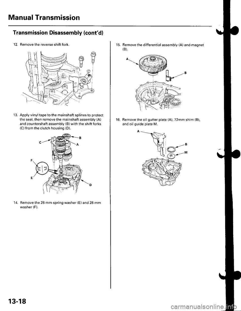
12. Remove the reverse shift fork.
Apply vinyl tape to the mainshaft splines to protect
the seal, then remove the mainshaft assembly (A)
and countershaft assembly (B) with the shift forks
{C)from the clutch housing (D).
14. Remove the 28 mm spring washer (E) and28mm
washer (F).
t7t1I
13-18
15. Remove the differential assembly (A) and magnet(B ).
Remove the oil gutter plate (A), 72mm shim (B),
and oil guide plate M.
16.
Page 429 of 1139
Reverse Shift Fork Clearance
Inspection
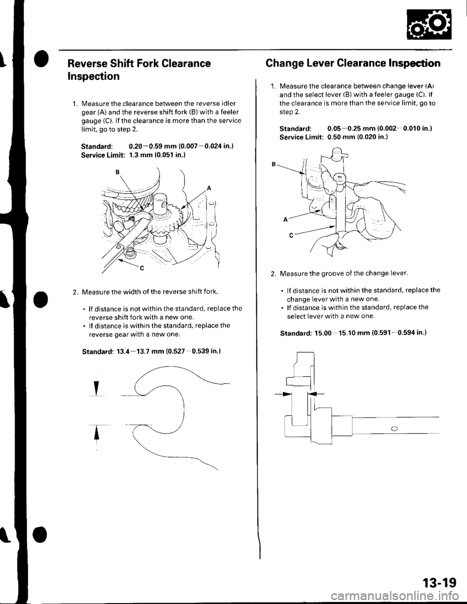
1. Measure the clearance between the reverse idler
gear {A) and the reverse shift fork (B) with a feeler
gauge (C). lf the clearance is more than the service
limit, go to step 2.
Standard: 0.20-0.59 mm (o.oo7 0.024 in.l
Service Limit: r.3 mm {0.051 in.)
Measu re the width of the reverse shift fork.
. lf distance is notwithinthestandard, replacethe
reverse shift fork with a new one.. lf distance is within the standard, replacethe
reverse gear wrln a new one.
Standard: 13.4 13.7 mm (0.527 0.539 in.l
I
Change Lever Clearance Inspection
1.Measure the clearance between change lever (Al
and the select lever (B) with a feeler gauge (Cf. lf
the clearance is more than the service limit, go ro
step 2.
Standard: 0.05 0.25 mm (0.002-0.010 in.)
Service Limit: 0.50 mm {0.020 in.)
2.Measure the groove of the change lever'
. lf distance is not within the standard, replace the
change lever with a new one.
. lf distance iswithinthe standard, replacethe
select lever with a new one.
15.00 15.10 mm (0.591-0.594 in.)Standard:
,tl
I
qI
13-19
Page 430 of 1139
Manual Transmission
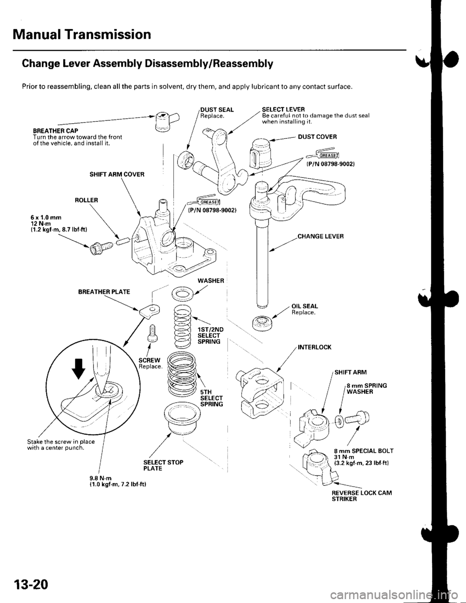
Change Lever Assembly Disassembly/Reassembly
Prior to reassembling, clean all the parts in solvent, dry them, and apply lubricant to any contact surface.
BREATHER CAPTurn the arrow toward the {ronto{ the vehicle, and install it.
SELECT LEVERBe careful not to damage the dust sealwhen installing it.@).1 IlLrl
rrl
I
DUST COVEB
a^^
7 Fr"irr6-rooa
(P/N 08798-9002)
ROLLER
6x1.0mm12 N.m(1.2 kgl.m,8.7 lbf.ft)
'^ E-='-Fl !-d 1sr/2Noq )-=^l sELEcr
i €2 sPntruc
,.* (A)tace. ix�#,,l
H\
lV srxSELECT-z:-=:l-': SPRING
r\
tr7
,/u
/
\op
(g)'
' -, OIL SEAL,/ ReDlace./-r,s
\__/
INTERLOCK
SHIFT ARM
SELECT STOPPLATE
REVERSE LOCK CAMSTRIKER
SHIFT ARM COVER
WASHER
9.8Nm{1.0 kgf.m, 7.2 lbf.ft)
13-20
Page 431 of 1139
Shift Forks Glearance Inspection
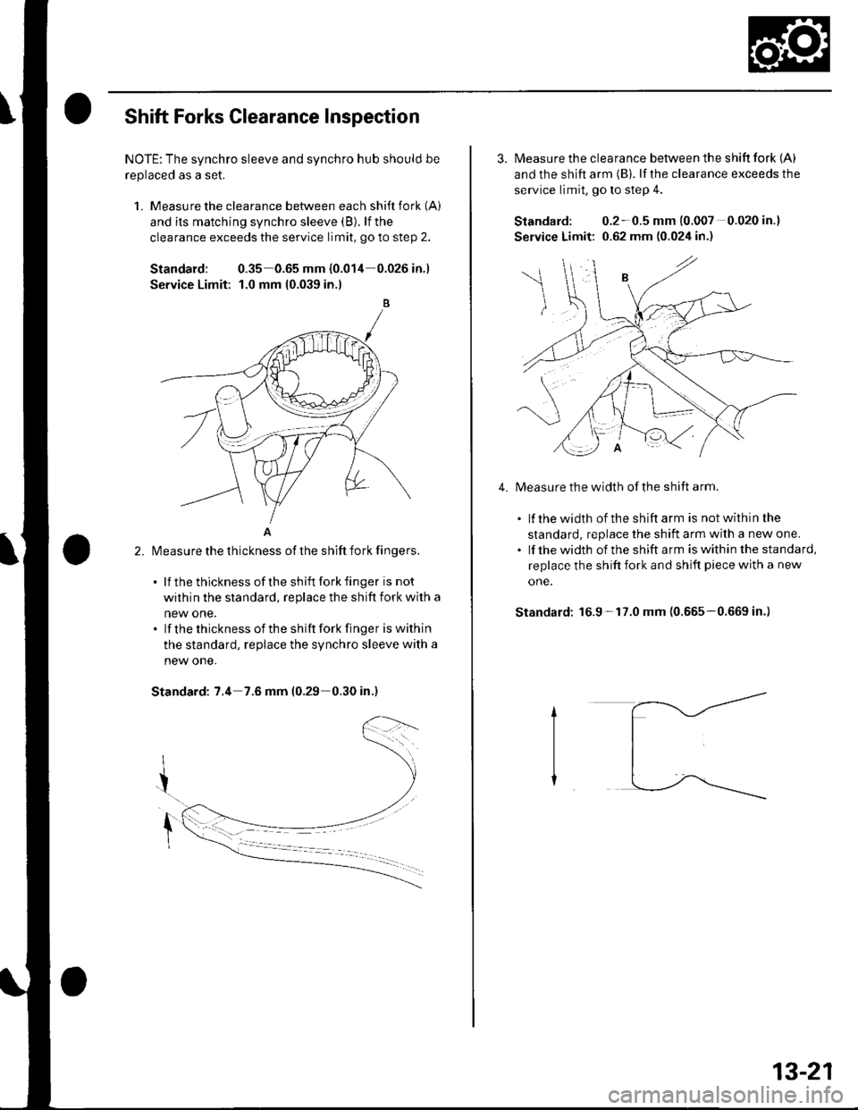
NOTE: The synchro sleeve and synchro hub should be
replaced as a set.
1. Measu re the clearance between each shift fork (A)
and its matching synchro sleeve (B). lf the
clearance exceeds the service limit, go to step 2.
Standard: 0.35 0.65 mm {0.014 0.026in.1
Service Limit: 1.0 mm 10.039 in.l
A
l\4easure the thickness of the shift fork fingers.
. lf thethicknessof theshift forkfinger is not
within the standard, replace the shift fork with a
new one.. lf thethicknessof the shift forkfinger iswithin
the standard, replace the synchro sleeve with a
new one.
Standard: 7.4 7.6 mm (0.29-0.30 in.)
2.
3. Measure the clearance between the shift fork (A)
and the shift arm (B). lf the clearance exceeds the
service limit, go to slep 4.
Standard: 0.2-0.5 mm (0.007 0.020 in.)
Service Limit: 0.62 mm (0.024 in.)
Measure the width of the shift arm.
. lf thewidth of theshiftarm is notwithinthe
standard, replace the shift arm with a new one.. lf thewidth of the shift arm iswithinthe standard,
replace the shift fork and shift piece with a new
one.
Standard: 16.9-17.0 mm (0.665-0.669 in.)
4.
13-21
Page 432 of 1139
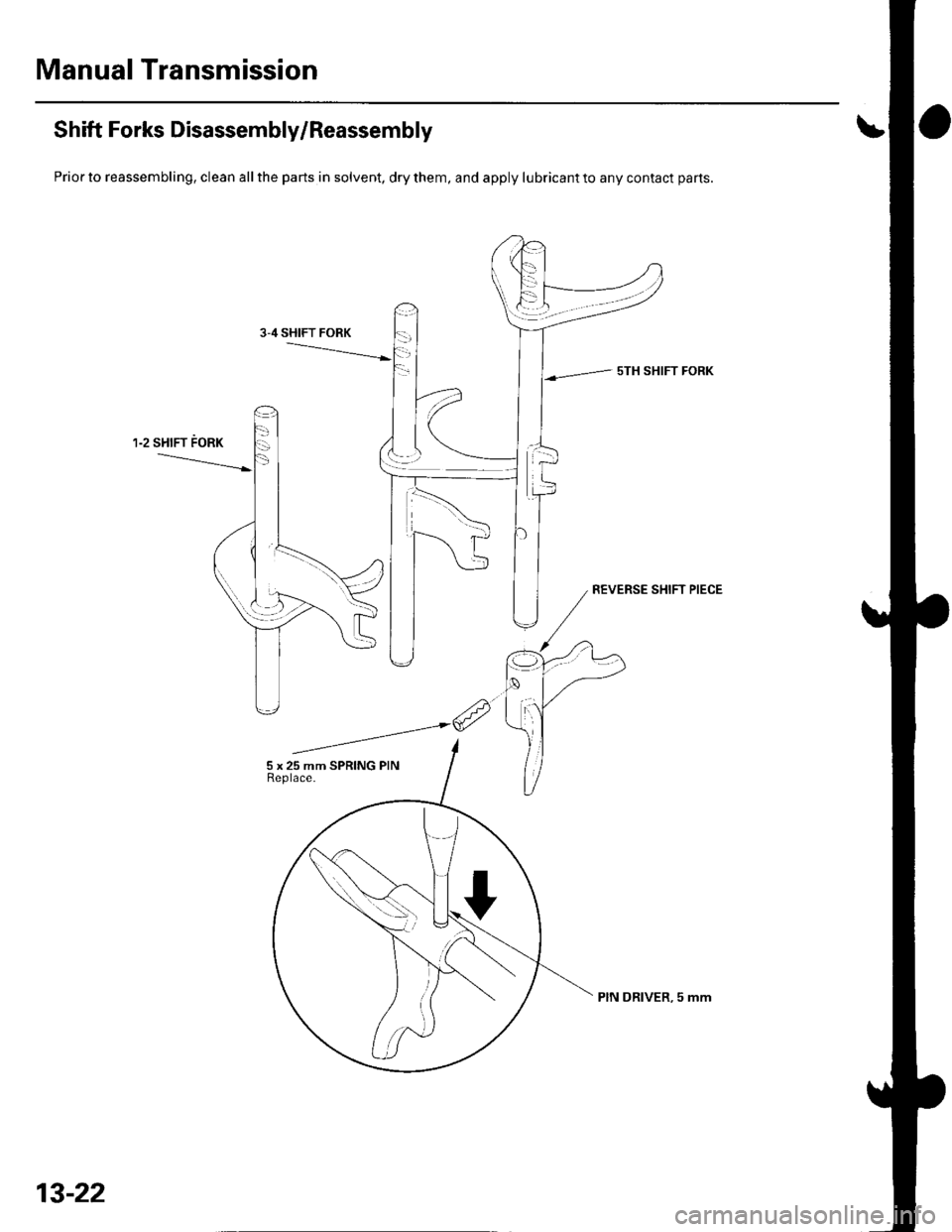
Manual Transmission
Shift Forks Disassembly/Reassembly
Prior to reassembling, clean all the parts in solvent, dry them, and apply lubricant to any contact parts.
sTH SHIFT FORK
13-22
PIN DRIVER, 5 mm
Page 456 of 1139
Manual Transmission
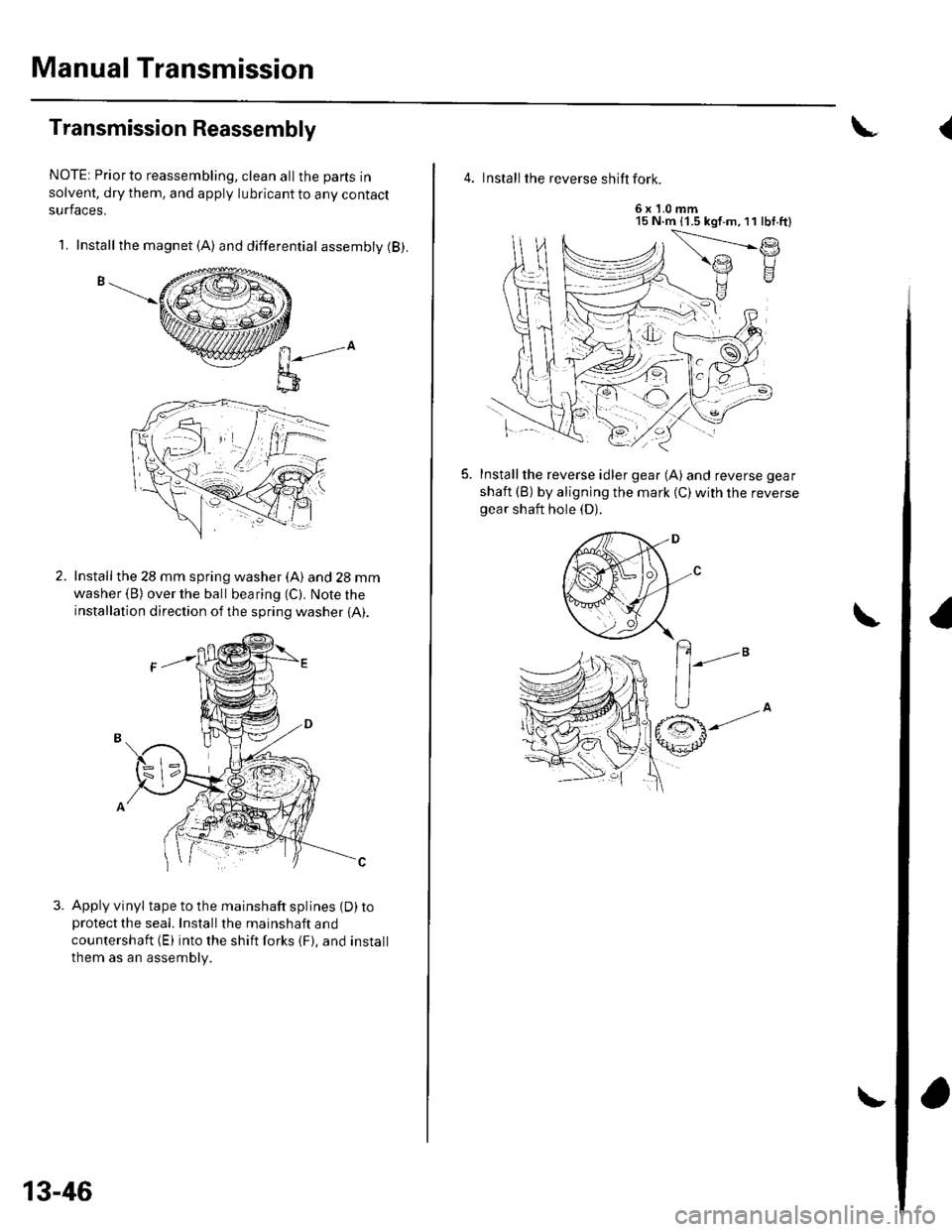
Transmission Reassembly
NOTE: Priorto reassembling, clean allthe parts in
solvent, dry them, and apply lubricant to any contact
surfaces.
1. Install the magnet (A) and differential assembly (B).
n-",-o
l;-D
Install the 28 mm spring washer (A) and 28 mm
washer (B) over the ball bearing (C). Note the
installation direction of the spring washer {A).
Apply vinyl tape to the mainshaft splines (D) toprotectthe seal. Installthe mainshaft and
countershaft (E) into the shift forks {F}. and install
them as an assembly.
13-46
\
4. Install the reverse shift fork.
6x1.0mm15 N.m (1.5 kgf.m,11 lbf.ft)
f.)
Installthe reverse idler gear (A) and reverse gear
shaft (B) by aligning the mark {C)with the reversegear shaft hole (D).
(
Page 459 of 1139
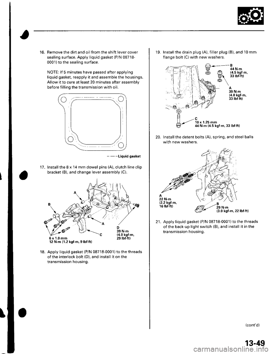
16. Remove the dirt and oil from the shift iever cover
sealing surface. Apply liquid gasket (P/N 08718-
0001) to the sealing surface.
NOTE: lf 5 minutes have passed after applylng
liquid gasket. reapply it and assemble the housings.
Allow it to cure at least 20 minutes after assembly
before filling the transmission with oil.
- - -Liquid gasket
17. Installthe 8 x 14 mm dowel pins (A). clutch line clip
bracket (B), and change lever assembly (C).
12 N.m (1.2 kgf.m,9lbt ft)
18. Apply liquid gasket (Pi N 08718-0001) to the threads
of the interlock bolt (D), and install it on the
transmission housing.
6x1.0mm
19. Installthe drain plug (A), filler plug (B), and 10 mm
flange bolt (C) with new washers.
A39Nm(4.0 kgf m,33 tbl.ft)
20.
/..l-.=,'-Bg ^ 44N.m
@ Ut !?iJl'.'l,''
R\-: \
-.-t ?0, ,.ru ^44 N m {4.5 kgt m,33lbf.ft}
Installthe detent bolts (A), spring, and steel balls
with new washers.
{3.0 kgf.m.22lbf.ft)
Apply liquid gasket {P/N 08718-0001}to the threads
oithe back-up light switch (B), and install it in the
transmission housing.
(cont'd)
21.
13-49
Page 461 of 1139
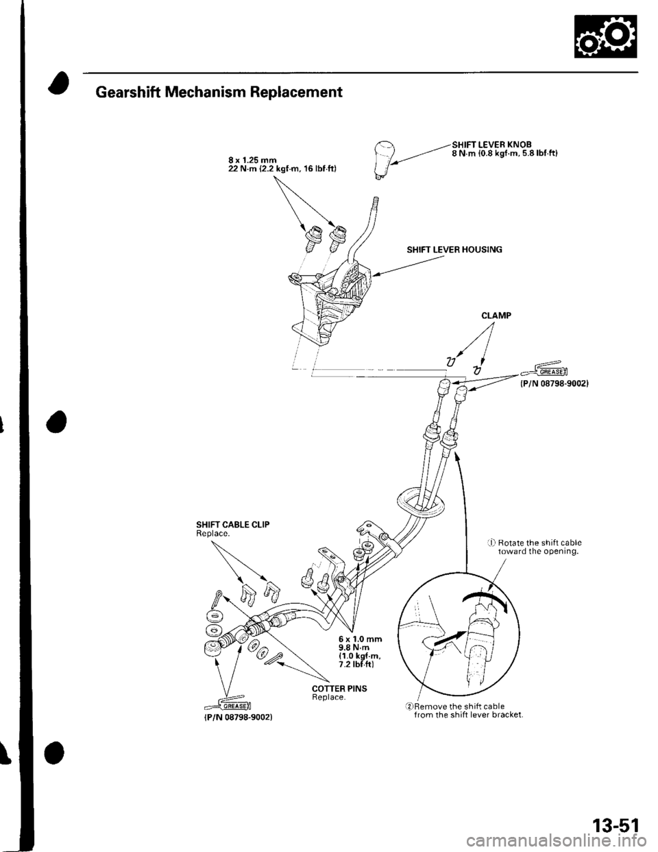
Gearshift Mechanism Replacement
SHIFT CABLE CLIPReplace.
8 x 1.25 mm22 N.m (2.2 kgf.m, 16 lbt ftl
--SHIFT LEVER KNOB
/ ,.-,'-' 8 N m {0.8 ksr.m. 5.8lbf.ft}
l'/
SHIFT LEVER HOUSING
{P/N 08798-9002}
r-Ll Rotate the shift cabletoward the opening.
6x1.0mm9.8Nm(1.0 kgf.m,7.2 tbf.fr)
COTTER PINS
qrBemove the shift cablefrom the shift lever bracket.{P/N 08798-9002)
13-51
Page 654 of 1139
Body
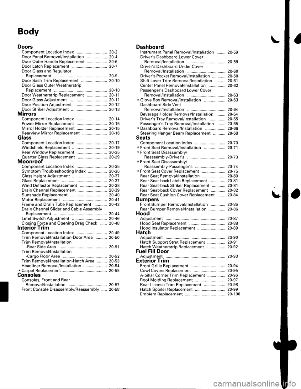
DoorsComponent Location Index ...........Door Panel Removal/lnstallation .....,..........Door Outer Handle ReplacementDoor Latch ReplacementDoor Glass and RegulatorReplacementDoor Sash Trim Replacement .......................
Door Glass Outer WeatherstripReplacement
Door Weatherstrip Beplacement
Door Glass Adjustment .................................Door Position Adjustment .............................Door Striker Adiustment ................................MirrorsComponent Location Index ...........................Power Mirror Replacement ...........................Mirror Holder Replacement ...........................Rearview Mirror Rep1acement ......................
GlassComponent Location Index ...........................Windshield Replacement
Bear Window Rep1acement ...........................
Ouarter Glass Replacement ..........................MoonroofComponent Location Index ...........................Symptom Troubleshooting Index
Glass Height Adjustment ...............................
Glass ReplacementWind Def lector 8ep1acement ........................Drain Channel Rep1acement ..........................Sunshade Replacement .................................Motor ReplacementFrame and Drain Tube Replacement ............Drain Channel Slider and Cable AssemblyReplacementLimit Switch Adjustment ...............................Closino Force and ODenina Draq Check ......lnterioi TrimComponent Location Index ...........................Trim Removal/lnstallation DoorArea ..........Trim Removal/lnstallation-Rear Side AreaTrim Removal/lnstallation-Cargo Floor AreaTrim Removal/lnstallation-Hatch Area .........Headliner Removal/lnstallation* Carpet Rep1acement .......................................ConsolesConsoles, Front and RearRemova l/lnsta llationFront Console Disassembly/Reassembly .....
20-220,420-620-7
20-920 t0
20- 10
20-1120-1120-1220 13
20-1420-1520-1520-16
20 1120-1920-2520-29
20,3520-3620-3720-3120-3820 3920-4020-4120,42
20 4420-4620,44
20-4920 50
20-51
DashboardInstrument Panel Removal/lnstallation ........Driver's Dashboard Lower CoverRemovat InstallationDriver's Dashboard Under CoverRemova t Insta llation
Oriver's Pocket Removal/lnstallation ............Shift Lever Trim Removal/lnstallation ..........Center Panel Removal/lnstallation ...............Passenger's Dashboard Lower CoverRemova l/lnsta llat ionx Glove Box Removal/lnstallationDashboard Side VentRemoval/lnstallation .................................. 20-64Beverage Holder Removal/lnstallation ........ 20-64Driver'sTray Removal/lnstallation ............... 20-65Passenger's Tray Removal/lnstallation ........ 20 65* Dashboard Removal/lnstallation .................. 20-66Steerinq Hanqer Beam Reolacement ........... 20-68Seats "
Component Location Index ........................... 20-10* Front Seat Removal/lnstallation ................... 20-11* Front Seat Disassembly/Reassembly-Driver's .................................. 20-73* Front Seat Disassembly/Reassembly-Passenger's ........................... 20-74* Front Seat Cover Replacement ..................... 2O-75Rear Seat Removal/1nsta11ation ..................... 20-80Rear Seat-back Latch Replacement .............. 20-81Rear Seat-backStriker Replacement ............ 20-81
20-59
20-59
Rear Seat-back Cover Replacement ............. 20-82Rear Seat Cushion Cover Replacement ....... 20.84BumpersFront Bumper Removal/lnstallation .............Rear Bumoer Removal/lnstallation ...............HoodAdjustmentHood Seal ReplacementHood Insulator Rep1acement .........................Hatch
20-6020,6020 6120-62
20-63
20-63
20,8520-86
20-4720,8820,89
20-5220-5320-5420-55
20-5720-58
Adjustment ................... 20-90Hatch Suppon Strut Replacement ................ 20-91Hatch WeatherstriD Reo1acement ................. 20-92
Fuel Fill DoorAdiustment ................... 20-93Exterior TrimFront Grille Replacement ..............Cowl Covers Replac"rn""t .. . .....................A pillar Corner Trim Replacement ................Roof lMolding Replacement ...........................Rear License Trim ReplacementHatch Spoiler 8ep1acement ...........................Emblem Rep1acement .........................
20-9420-9520-9620-9720,9820-9920-100
Page 715 of 1139
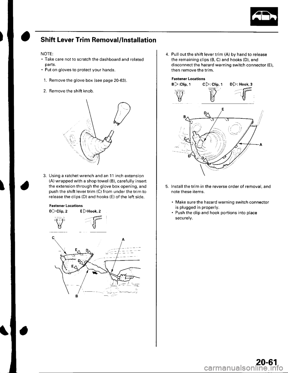
Shift Lever Trim Removal/lnstallation
NOTE:. Take care not to scratch the dashboard and related
pa rts.. Put on gloves to protect your hands.
1. Remove the glove box (see page 20-63).
2. Remove the shift knob.
Using a ratchet wrench and an 11 inch extension(A) wrapped with a shop towel (B), carefully insert
the extension through the glove box opening, andpush the shift lever trim (C) from under the trim to
release the clips (D) and hooks (E) of the left side.
Fastener
D>clip,
i:F\V
Locations
2 E >Hook,2
.-a7
-t1
u
4. Pull outthe shift levertrim (A) by hand to release
the remaining cllps (8, C) and hooks (D), and
disconnect the hazard warning switch connector (El,
then remove the trim.
Fastener Locations
B >:Clip, 1C>: Cl;p, 1 D>: Hook,3
,,.;w,
Install the trim in the reverse order of removal, and
note these rtems.
. Make sure the hazard warning switch connectot
is plugged in properly.. Push the clip and hook portions into place
securely,
-
,,
20-61