window HONDA CIVIC 2002 7.G Owner's Manual
[x] Cancel search | Manufacturer: HONDA, Model Year: 2002, Model line: CIVIC, Model: HONDA CIVIC 2002 7.GPages: 1139, PDF Size: 28.19 MB
Page 831 of 1139
\Body Electrical
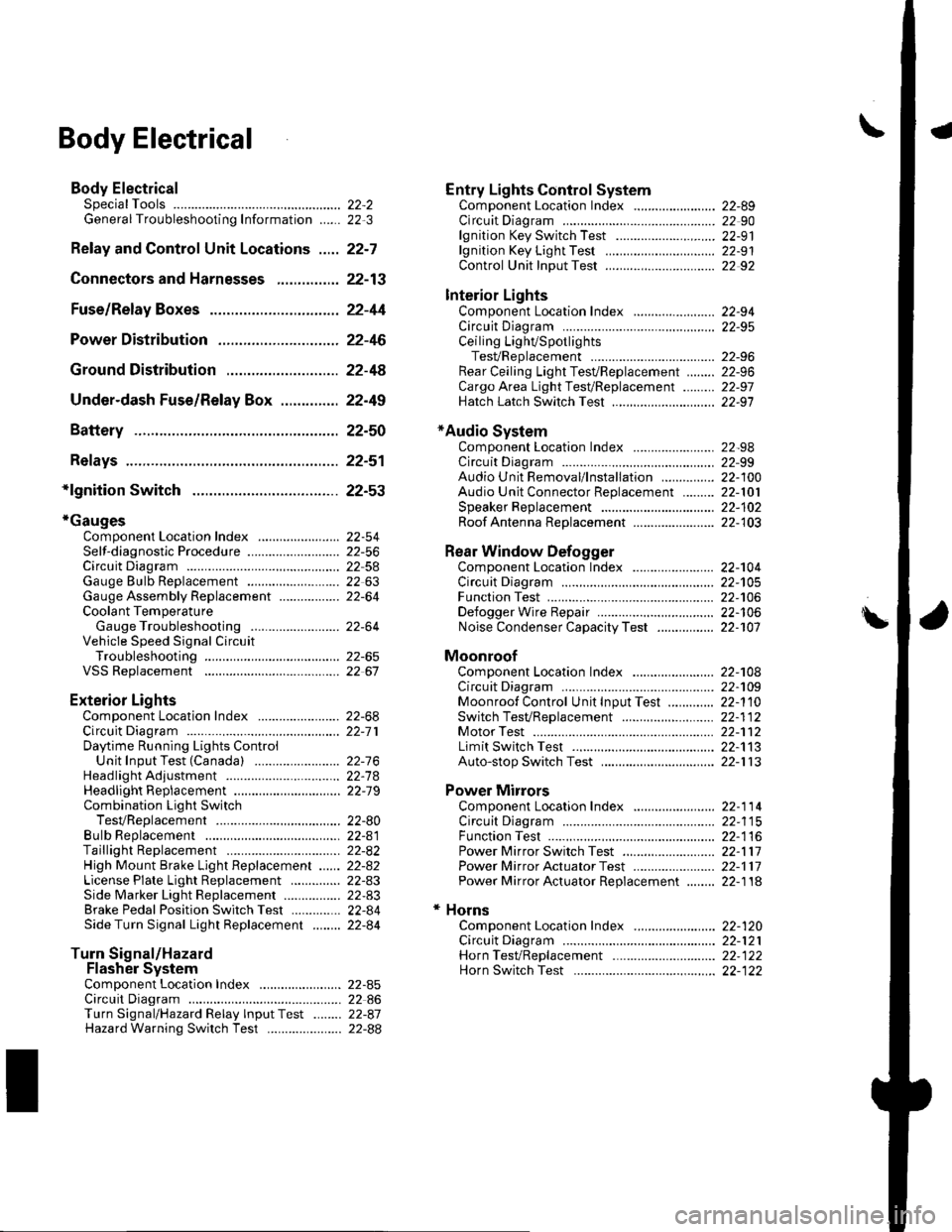
Body ElectricalSpecialToolsGeneral Troubleshooting tntorrnaiion.'......
Relay and Control Unit Locations .....
Connectors and Harnesses
Fuse/Relay Boxes ...............................
Power Distribution .............................
Ground Distribution ...........................
Under-dash Fuse/Relay Box ..............
Battery ..............
Relays ................
*lgnition Switch ..............
*Gauges
Component Location Index .......................Self-diagnostic Procedure ..........................Circuit DiagramGauge Bulb Replacement ..........................Gauge Assembly ReplacementCoolant Temperature
Gauge Troubleshooting .... ....................Vehicle Speed Signal CircuitTroubleshootingVSS Replacement
Exterior LightsComponent Location Index .......................Circuit DiagramDaytime Running Lights ControiUnit Input Test (Canada) ........................Headlight Ad,ustment .................. .. .....Headlighr Replacement ..............................Combination Light SwitchTest/ReplacementBulb ReplacementTaillight Replacement ..........................High Mount Brake Light Replacement ......License Plate Light Replacement ..............Side Marker Light Replacement ................Brake Pedal Position Switch Test ..............Side Turn Signal Light Replacement ........
Turn Signal/HazardFlasher SystemComponent Location Index .......................Circuit DiagramTurn Signal/Hazard Relay lnputTest ........Hazard Warning Switch Test
22,3
22-7
22-13
22-44
22-46
22-4A
22-49
22-50
22-51
22-53
22-5422-5622-5422 6322-64
22-64
22-6522 61
22-6822--71
22-7 622-7422-79
22-AO22-4122-8222-4222-4322-4322-4422-84
22-8�522 A622-8722-88
22-10422-105
22-10622-107
Entry Lights control systemComponent Location Index ....................... 22-89Circuit Diagram ......... 22 90lgnition Key Switch Test .....................,...... 22-9'llgnition Key Light Test ............................... 22-91Control Unit Input Test ..........,.................... 22 92
Interior LightsComponent Location Index ....................... 22-94Circuit Diagram ......... 22-95Ceiling LighVSpotlightsTesVReplacement ................................... 22-96Rear Ceiling Light TesVReplacem ent ........ 22-96Cargo Area Light Test/Replacem ent ......... 22-97Hatch Latch Switch Test ..,..,....................... 22-97
*Audio SystemComponent Location Index ....................... 22-98Circuit Diagram ......... 22,99Audio Unit Removal/lnstallation ............... 22-1OOAudio Unit Connector Replacement ......... 22-101Speaker Replacement ................................ 22-102Roof Antenna Rep1acement ....................-.. 22-103
Rear Window DefoggerComponent Location Index ...........Circuit Diasram .. ....... .. ..... ....... ...:::::.::.::.Function TestDefogger Wire Repair .................................Noise Condenser CapacityTest ................
MoonroofComponent Location Index ....................... 22-1OBCircuit Diagram ......... 22-109Moonroof Control Unit Input Test ............. 22-'l10Switch TesVReplacement ........,.....,........... 22-1 12Motor Test ................. 22-112Limit Swilch Test ...... 22-'l'13Auto-stop Switch Test ................................ 22-1 13
Power MirrorsComponent Location Index ....................... 22-114Circuit Diagram ......... 22-115Function Test ............. 22-116Power Mirror Switch Test .......................... 22-ll7Power Mirror Actuator Test ....................... 22-117Power Mirror Actuator Replacement ........ 22-11A
* HornsComponent Location Index ....................... 22-120Circuit Diagram ......... 22-121Horn TesVReplacement ...........................-. 22-122Horn Switch Test .,.... 22-122
\
Page 832 of 1139
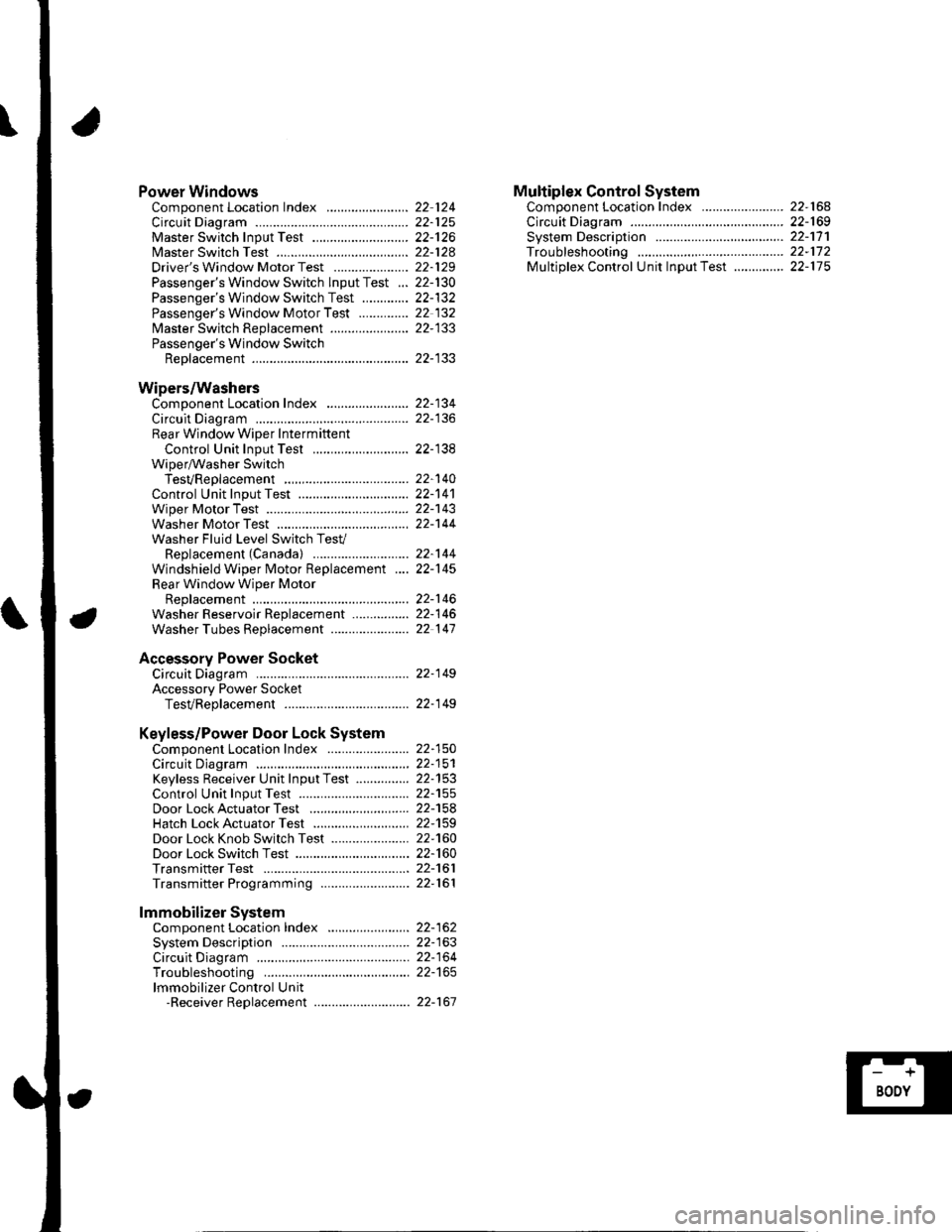
Power WindowsComponent Location Index ..........
circuit Diagram . .. ............... .........:.::::.::::.:Master Switch Input Test ...........................Master Switch TestDriver's Window Motor Test .....................
Passenger's Window Switch lnput Test ...Passenger's Window Switch Test .............
Passenger's Window Motor Test ..............
lMaster Switch Replacement ......................
Passenger's Window SwitchReplacement
Wipers/WashersComponent Location Index .......................
Circuit DiagramRear Window Wiper Intermiftent
Control Unit Input Test ...........................Wiper/Washer SwitchTesVReplacementControl Unit Input Test ...............................Wiper Motor Test
Washer Motor TestWasher Fluid Level Switch TesV
Replacement (Canadal ..........................
Windshield Wiper Motor Replacement ....
Rear Window Wiper MotorReplacementWasher Reservoir Replacement ................
Washer Tubes Beplacement ......................
Accessory Power SocketCircuit Diagram ......... 22-149
Accessory Power Socket
TesVReplacement ................................... 22-1 49
Keyless/Power Door Lock System
Component Location Index ....................... 22-150
Circuit Diagram ......... 22-151Keyless Receiver Unit InputTest ............... 22-153
Control Unit Input Test ............................... 22-155
Door LockActuatorTest .........,.......,..,.,..... 22-158Hatch LockActuatorTest ........................... 22-159
Door Lock Knob Switch Test ...................... 22-160
Door Lock Switch Test ................................ 22-160
Transmitter Test ....... 22-161
Transmitter Programming ......................... 22-161
Multiplex Control SystemComponent Location Index ...........
circuit Diagram ...... ........................::.:..:.::.:
Svstem DescriDtionTroubleshootingMultiolex Control Unit InDut Test .............
22 12422-12522-12622-12822-129
22- t30
22-13222 13222-133
22-133
22-134
22-138
22-14022-14122-14322-144
22-14422-145
22-14622-14622 147
22,16422-16922-17'l22,11222-175
lmmobilizer Systemcomponent Location Index ...........
System Description ....... ............. ..:..:..:.:...
Circuit DiagramTroubleshootinglmmobilizer Control Unit-Receiver Replacement ...........................
22-16222-16322-164
22-167
Page 842 of 1139
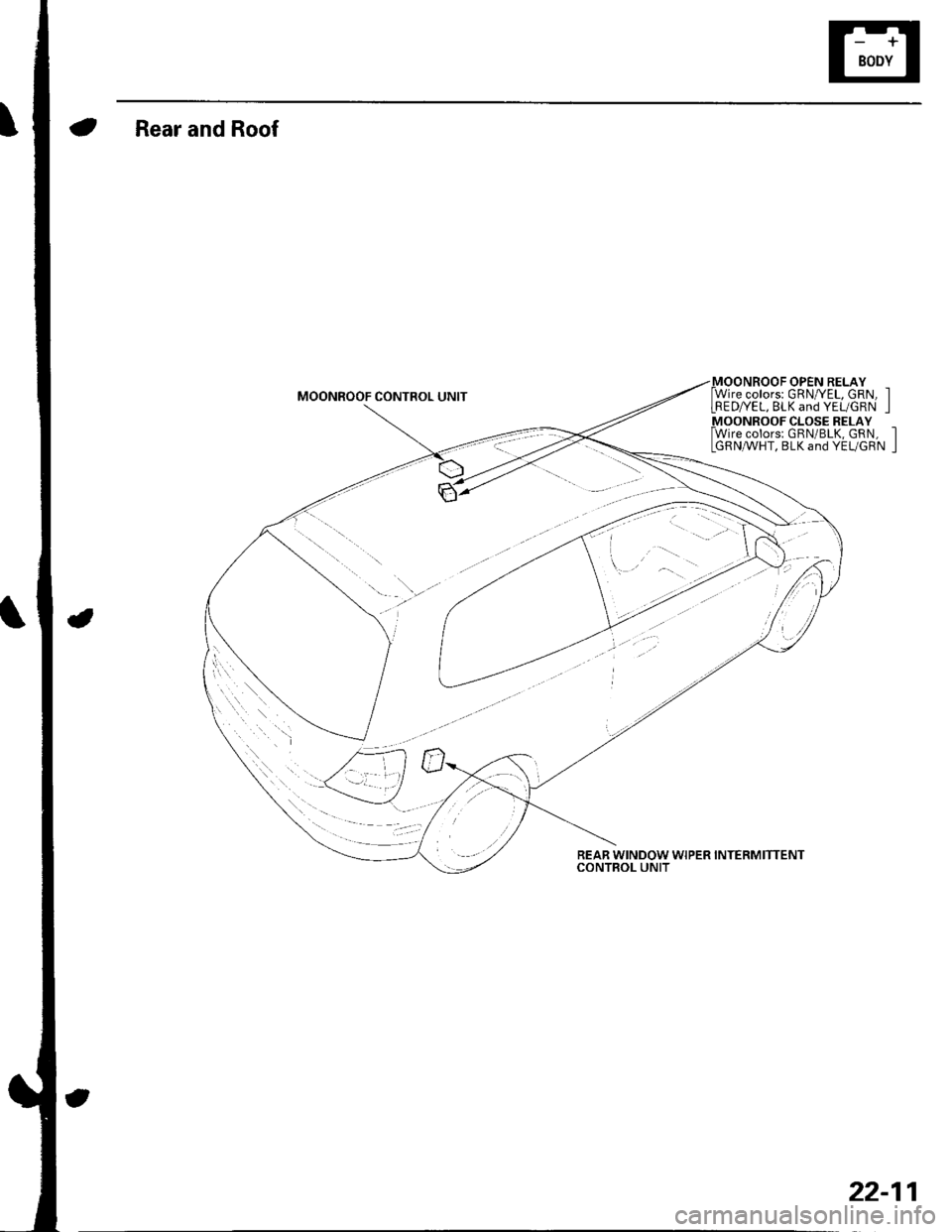
Rear and Roof
MOONROOF OPEN RELAY -Wire colors: GRNI/EL, GRN, ILRED/YEL, BLK and YEL/GRN IMOONROOF CLOSE RELAY
REAR WINDOW WIPER INTERMITTENTCONTBOL UNIT
fwire colors: GRN/BLK, GRN, lIGRN,AtVHT, BLK and YEL/GRN I
22-11
Page 843 of 1139
![HONDA CIVIC 2002 7.G Owners Manual Relay and Control Unit Locations
Door and Seat
Drivers Door:
Passengers Seat:
l\:
].\
POWER WINDOW MASTER SWITCHlHas built-in control unit)
22-12 HONDA CIVIC 2002 7.G Owners Manual Relay and Control Unit Locations
Door and Seat
Drivers Door:
Passengers Seat:
l\:
].\
POWER WINDOW MASTER SWITCHlHas built-in control unit)
22-12](/img/13/5744/w960_5744-842.png)
Relay and Control Unit Locations
Door and Seat
Driver's Door:
Passenger's Seat:
l\:
].\
POWER WINDOW MASTER SWITCHlHas built-in control unit)
22-12
Page 867 of 1139
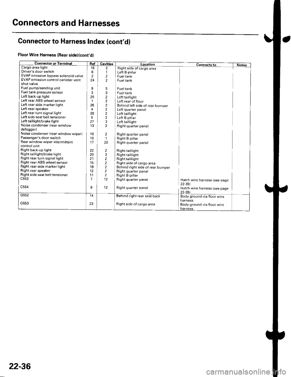
Gonnectors and Harnesses
a
Floor Wire Harness {Rear side}(cont'dl
Cargo areaDriver's door switchEVAP emission bypass solenoid valveEVAP emission control canister ventshut valveFuel pump/sending unitFuel tank pressure sensorLeft back-up lightLeft rear ABS wheel sensorLeft rear side marker lightLeft rear speakerLeft rear turn signal lightLeft side seat belt tensionerLeft taillighVbrake lightNoise condenser (rear windowdefogger)Noise condenser (rear window wiper)Passenger's door switchRear window wiper intermiftentcontrolunitRight back-up lightRight taillighvbrake tightRight rear turn signal lightBight rear ABS wheel sensorRight rear side marker lightRight rear speakerRight side seat belt tensioner
c554
Fueltank
FueltankFueltankLeft taillightLeft rear offloorBehind left side of rear bumperLeft quarter panelLefttaillightLeft B-pillarLeft taillightRight quarter panel
Right quarter panelRight B pillarRight q uarter panel
Right tai ightRight taillightRight taillightRight side of cargo area
side of cargo areaLeft B pillarFueltank
Right quaner panel
6224
I32512642A527'13
181011
222021151912117
I
2122
5322222232
232222212
12
2120
Behind right side of rear bumperRight quaner panelRight B-pillarRight quaner panelHatch wire harness (see page22 39)Hatch wire harness (see page
rear seal bdcl Bodv ground vta
Right side of cargo area Body ground via floor wire
Connector to Harness Index (cont'dl
22-36
Page 870 of 1139
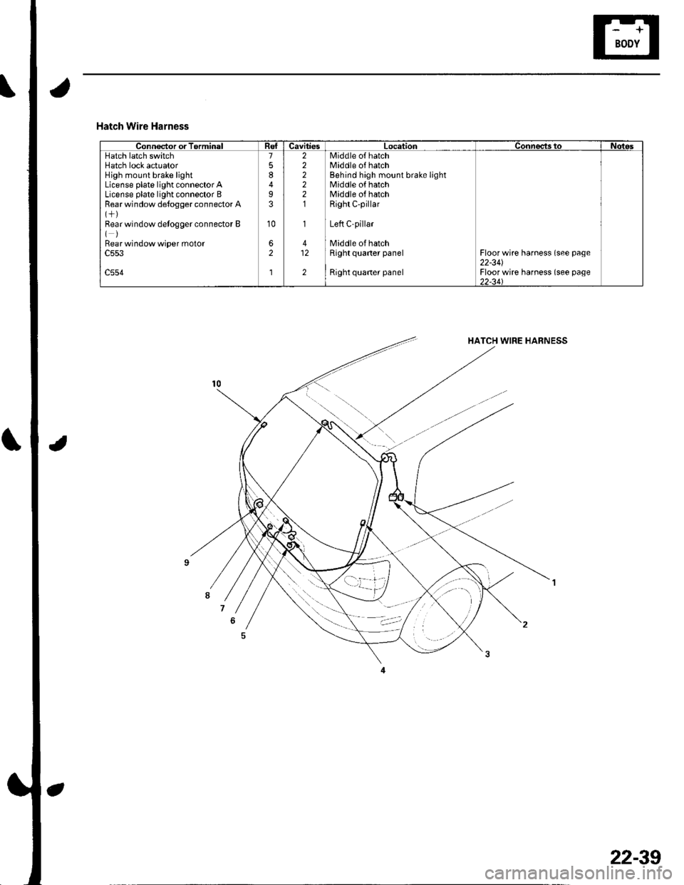
Hatch Wire Harness
Connector or TorminalCavitiesLocationConnects toNotesHatch latch switchHatch lock actuatorHigh mount brake lightLicense plate light connector ALicense plate light connector BRear window de{ogger connector A
Bear window detogger connector B()Bear window wiper moto.c553
c554
7
8
I3
10
62
l
222221
1
412
2
Middle o{ hatchMiddle of hatchBehind high mount brake lightMiddle of hatchMiddle of hatchRight C-pillar
Left C-pillar
Middle of hatchRight quaner panel
Right quaner panel
Floor wire harness (see page22-341Floor wire harness (see page)2-34\
22-39
Page 871 of 1139
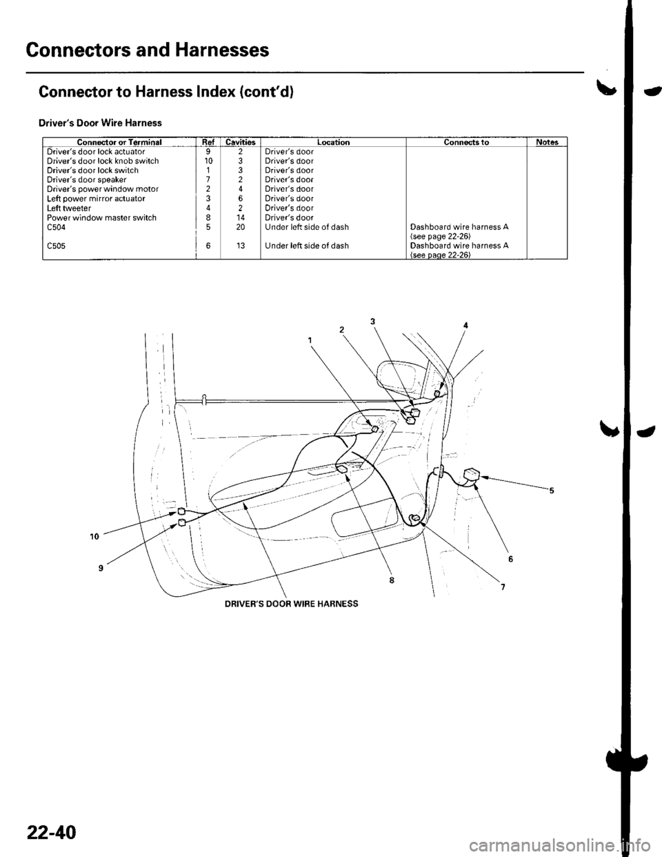
Connectors and Harnesses
\,Connector to Harness lndex (cont'd)
Driver's Door Wire Harness
Connector or TerminalReICavitiesLocationConnectstoNotesDriver's door lock actuatorDriver's door lock knob switchDriver's door lock switchDriver's door speakerDriver's power window motorLeft power mirror actuatorLeft tlveeterPower window master switchc504
c505
9101723
85
6
2332
62
20
't3
Driver's doorDriver's doorDriver's doorDriver's dooaDriver's doorDriver's doorDriver's doorDriver's doorUnder left side of dash
Under left side of dash
Dashboard wire harness A\see page 22-261Dashboard wire harness A
DRIVER'S OOOR WIRE HABNESS
22-40
Page 872 of 1139
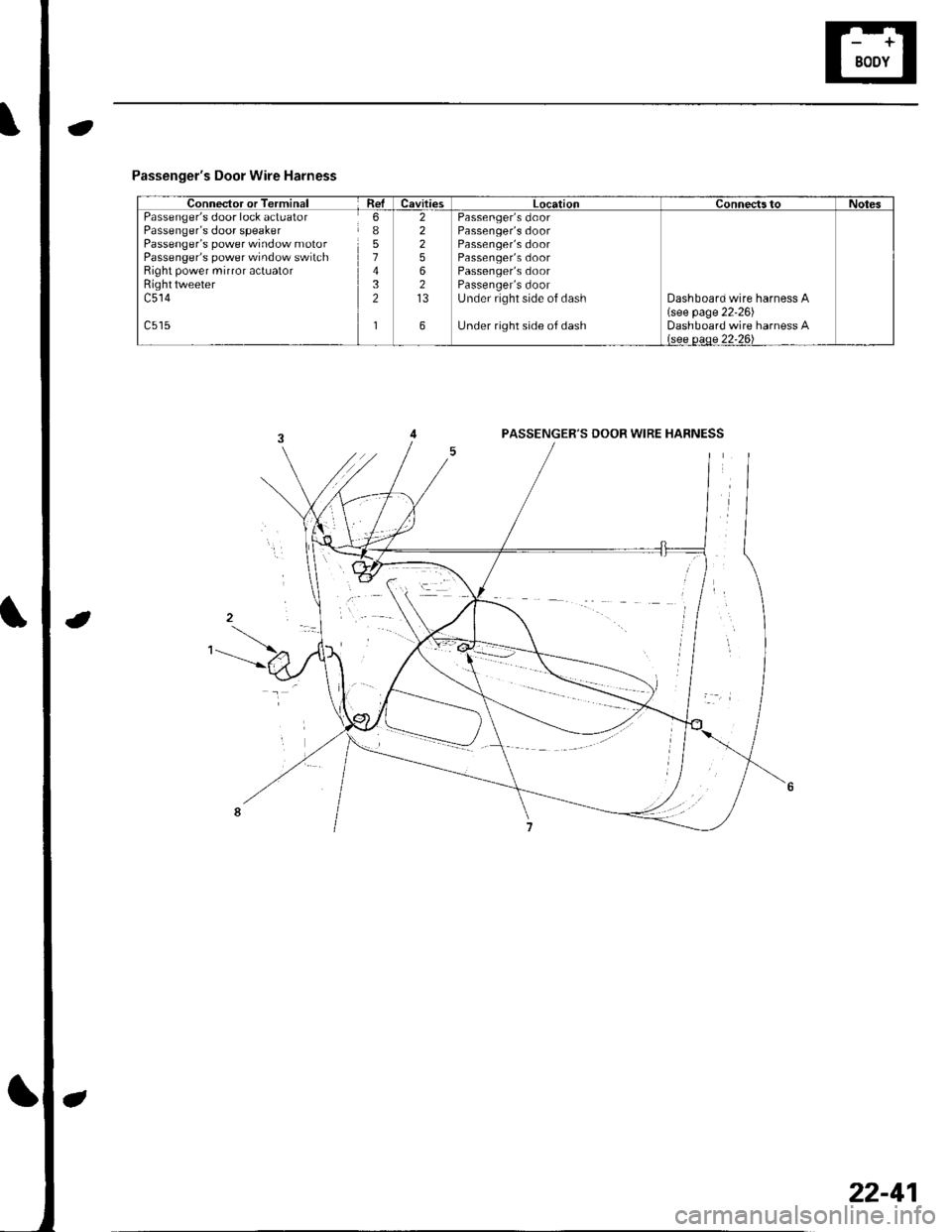
Passenger's Door Wire Harness
Connector or TerminalRelCavitiesLocationConnectstoNotesPassenger's door lock actuatorPassenger's door speakerPassenger's power window motorPassenger's power window switchRight power mirror actuatorRighttweeterc514
6I51432
1
22256213
6
Passenger's doorPassenger's doorPassenger's doorPassenger's doorPassenger's doorPassenger's doorUnder right side of dash
Under right side of dash
Dashboard wire harness A(see page 22'26)Dashboard wire harness Alsee oeoe 22-26\
PASSENGER'S DOOR WIRE HABNESS
22-41
Page 875 of 1139
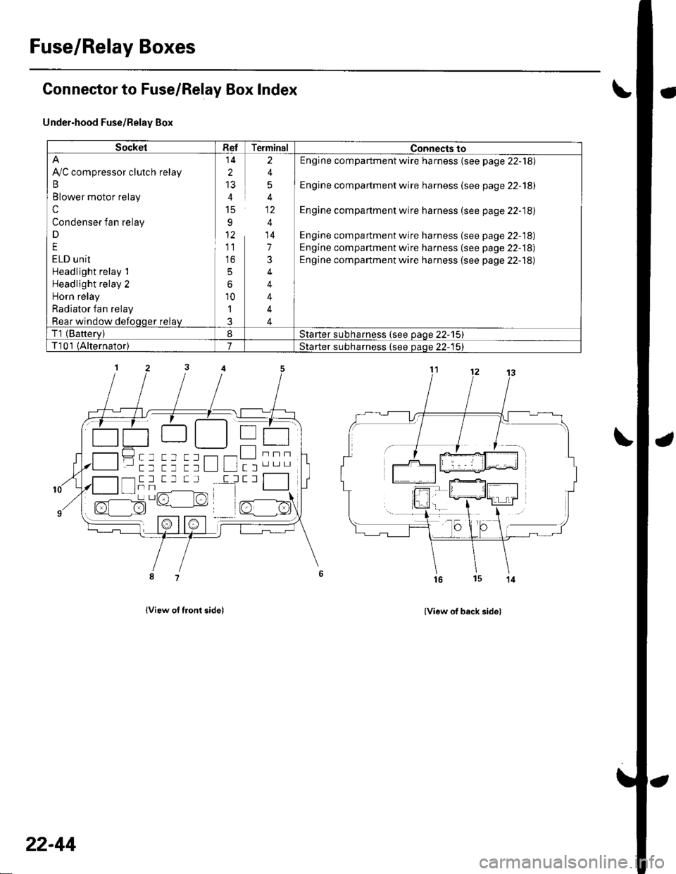
Fuse/Relay Boxes
Connector to Fuse/Relay Box Index
Under-hood Fuse/Relay Box
lview of tront sidel
- a-------) | | T---r .-:-tt || tL__.1 | I
------tttL""tt tt ttL lL ltl'".-
{View of back side)
SocketRefTerminalConnects to
Ay'C compressor clutch relay
B
Blower motor relay
c
Condenser fan relay
D
E
ELD unit
Headlight relay 1
Headlight relay 2
Horn relay
Radiator fan relay
Rear window defoqqer relay
14
2
15
91'
11
to
5
6
10'l
J
2
4
5
4
4
14
7
3
4
4
4
4
Engine compartment wire harness (see page 22-18)
Engine compartment wire harness (see page 22-18)
Engine compartment wire harness (see page 22-18)
Engine compartment wire harness (see page 22-18)
Engine compartment wire harness (see page 22-18)
Engine compartment wire harness {see page 22-18)
T1 (Batterv)8Starter subharness (see oaqe 22-15)
T101 (Alternator)7Starter subharness {see oaoe 22-'15}
""""-l- tr -l T _l T Il
I tTt Tr,/^-------lFrr^l -/1-l sz- l:!)L' lrt
22-44
Page 876 of 1139
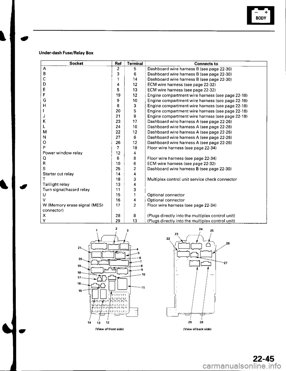
Under-dash Fuse/Relay Box
SocketRefTerminal Connects to
B
c
D
E
F
G
H
J
K
M
N
o
P
Power window relay
o
R
S
Starter cut relay
T
Taillight relay
Turn signal/hazard relay
U
W (Memory erase signal (MES)
connector)
X
Y
2
3
1
5
19
9
I
20
24
22
27
26
7
6
10
25
14
18
11
l5
to
17
28
5
6
14
13
12
10
3
:
11'10
1:
.o^
;;
4
8
2
i
nl
al
lt
2
Dashboard wire harness B {see page 22-30)
Dashboard wire harness B {see page 22-30)
Dashboard wire harness B (see page 22-30)
ECM wire harness (see page 22-32)
ECI\4 wire harness (see page 22-32)
Engine compartment wire harness (see page 22-'l8l
Engine compartment wire harness (se e page 22-181
Engine compartment wire harness (see page 22-18)
Engine compartment wire harness (se e page 22-18)
Engine compartment wire harness (see page 22-18)
Dashboard wire harness A (see page 22-26)
Dashboard wire harness A (see page 22-26)
Dashboard wire harness A (see page 22-26)
Dashboard wire harness A (see page 22-26)
Dashboard wire harness A (see page 22-26)
Floor wire harness (see page 22-34)
Floor wire harness (see page 22-34)
ECM wire harness (see page 22-32)
Dashboard wire harness B (see page 22-30)
Multiplex control unit service check connector
Optional connector
Optional connector
Floor wire harness (see page 22-34)
{Plugs directly into the multiplex control(Pluqs directlv into the multiDlex control
unat)
unrl)
I
13
tn--rlI U LI L.] L.Jh--n-UL]L]UL]
I] L] L] LI L]
!3 12
22-45