window HONDA CIVIC 2002 7.G User Guide
[x] Cancel search | Manufacturer: HONDA, Model Year: 2002, Model line: CIVIC, Model: HONDA CIVIC 2002 7.GPages: 1139, PDF Size: 28.19 MB
Page 678 of 1139
Glass
23.
24.
Windshield Replacement (cont'd)
Scrape or wipe the excess adhesive off with a putty
knife or towel. To remove adhesive from a painted
surface or the windshield, wipe with a soft shop
towel dampensd with alcohol.
Let the adhesive dry for at least t hour, then spray
water over the windshield and check for leaks.
Mark Ieaking areas, and let the windshield dry, then
seal with sealant:
. Let the vehicle stand for at least 4 hours after
windshield installation. lf the vehicle has to be
used within the first 4 hours, it must be driven
slowly.. Keep the windshield dry for the first hour after
installation.
Reinstallthe cowl covers (see page 20-95).
NOTE:The cowl cover clips may not set properly if
the windshield adhesive is too wet.
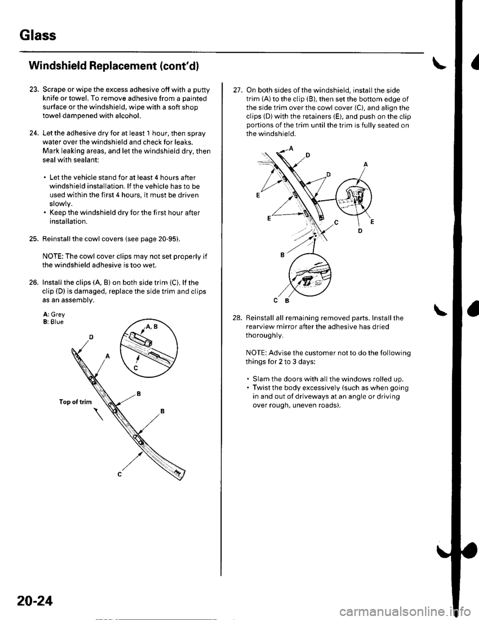
Install the clips (A, B) on both side trim {C). lf the
clip (D) is damaged, replace the side trim and clips
as an assembly.
A: GreyB: Blue
20-24
27. On both sides ofthe windshield, install the side
trim (Alto the clip (B), then set the bottom edge of
the side trim over the cowl cover (C), and align the
clips (D)with the retainers (E), and push on the clipportions of the trim until the trim is fully seated on
the windshield.
Reinstall all remaining removed parts. Installthe
rearview mirror after the adhesive has dried
thoroughly.
NOTE: Advise the customer not to do the following
things for 2 to 3 days:
. Slam the doors with allthe windows rolled up.. Twist the body excessively (such as when going
in and out of driveways at an angle or driving
over rough, uneven roads).
28.
Page 679 of 1139
Rear Window Replacement
NOTE:. Put on gloves to protect your hands.. Wear eye protection while cutting the glass adhesive
with piano wire.. Use seat covers to avoid damaging any surfaces.. Do not damage the rear window defogger grid lines
and terminals.
1.Remove these items:
. Hatch lower trim panel (see page 20-53). Hatch spoiler (see page 20-99)
Remove these items:
. High mount brake light {see page 22-821. Rear window wiper motor {see page 22-1461
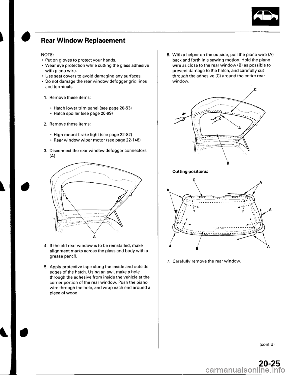
Disconnect the rear window defogger connectors
(A).
4.lf the old rear window is to be reinstalled, make
alignment marks across the glass and body with a
grease pencrl,
Apply protective tape along the inside and outside
edges of the hatch. Using an awl, make a hole
through the adhesive from inside the vehicle at the
corner portion of the rearwindow. Push the piano
wire through the hole, and wrap each end around a
piece of wood,
6. With a helper on the outside, pull the piano wire (A)
back and Jorth in a sawing motion. Hold the piano
wire as close to the rear window (B) as possible to
prevent damage to the hatch, and carefully cut
through the adhesive {C} around the entire rear
Cutting positions:
7. Carefully remove the rear window.
(cont'd)
20-25
Page 680 of 1139
Glass
Rear Window Replacement (cont'd)
With a putty kniie. scrape the old adhesive smooth
to a thickness of about 2 mm (0.08 in.) on the
bonding surface around the entire rear window
opening flange:
. Do not scraDe down to the Dainted surface of the
body; damaged paint will interfere with proper
bonding. Remove the fasteners from the tailqate.
Clean the hatch bonding surface with a sponge
dampened in alcohol. After cleaning, keep oil,grease and water from getting on the surface,
lf the old rear window is to be reinstalled, use a
putty knife to scrape off all of the old adhesive, the
fasteners and the rubber dams from the rear
window. Clean the inside face and the edge oi the
rear window with alcohol where new adhesive is to
be applied. Make sure the bonding surface is kept
free of water, oil and grease.
10.
20-26
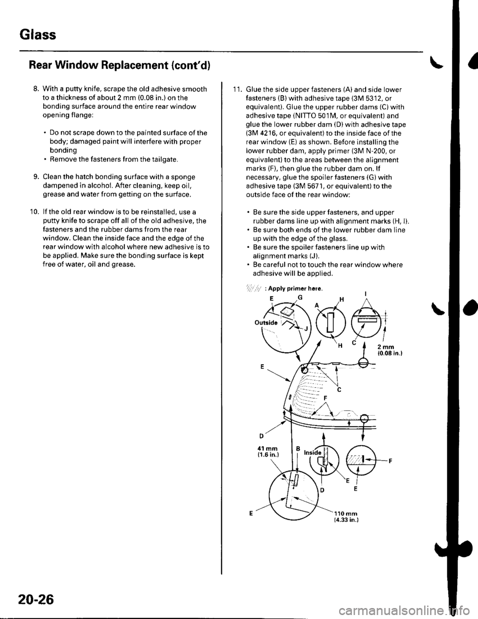
11. Glue the side upper fasteners (A) andsidelower
fasteners {B) with adhesive tape {3M 5312, or
equivalent). Glue the upper rubber dams (C)with
adhesive tape (NITTO 501fM, or equivalent) andglue the lower rubber dam (D) with adhesive tape(3M 4216, or equivalent) to the inside face of the
rear window (E) as shown. Before installing the
lower rubber dam, apply primer (3M N-200, or
equivalent) to the areas between the alignment
marks {F), then glue the rubber dam on. lf
necessary, glue the spoiler fasteners (G) with
adhesive tape (3M 5671, or equivalent) to the
outside face of the rear window:
. Be sure the side upper fasteners, and upper
rubber dams line up with alignment marks {H, l).. Be sure both ends of the lower rubber dam line
up with the edge of the glass,. Be sure the spoiler fasteners line up with
alignment marks {J).. Be careful not to touch the rear window where
adhesive will be aDolied.
1,1,.,1,' : Apply primer here.
E
"6'J1r-,
G
Page 681 of 1139
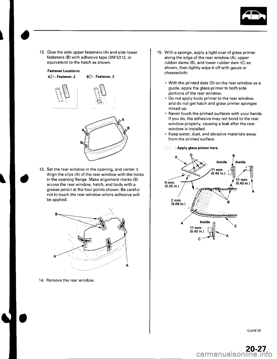
12. Glue the side upper fasteners (A) andsidelower
fasteners (B) with adhesive tape (3M 5312, or
equivalent)to the hatch as shown.
Fastoner Locations
A>: Fastener, 2 B >: Fastener, 2
T-8.
cl
ar\
itf,
t5.Set the rear window in the opening, and center it.
Align the clips (A) of the rear window with the holes
in the opening flange. Make alignment marks (B)
across the rear window, hatch, and body with a
grease pencil at the four points shown. Be careful
not to touch the rear window where adhesive will
be applied.
14. Remove the rear window.
15. With a sponge, apply a light coat of glass primer
along the edge of the rear window (A), upper
rubber dams (B), and lower rubber dam (C) as
shown, then lightly wipe it off with gauze or
cheesecloth:
. With the printed dots (D) on the rear window as a
guide, apply the glass primer to both side
portions of the rear window.. Do not apply body primer to the rear window,
and do not get hatch and glass primer sponges
mixed up.. Never touch the primed surfaces with your hands.
lf you do, the adhesive may not bond to the rear
window properly. causing a leak after the rear
window is installed.. Keep water, dust, and abrasive materials away
from the primed surface.
.. : Apply glass piimer here.
(cont'd)
20-27
Page 682 of 1139
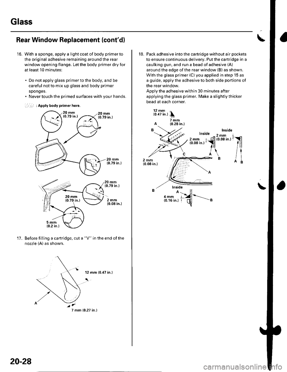
Glass
16.
Rear Window Replacement (cont'd)
With a sponge, apply a light coat of body primer to
the original adhesive remaining around the rear
window opening flange. Let the body primer dry for
at least 10 minutes;
. Do not apply glass primer to the body, and be
careful not to mix up glass and body primer
sponges.. Never touch the primed surfaces with your hands.
',,,,,' : Apply body primer he.e.
20 mm10.79 in.l
2mm{0.08 in.)
17.Before filling a cartridge, cut a "V" in the end ofthe
nozzle {A} as shown.
20-28
7 mm (0.27 in.)
I
18. Pack adhesive into the cartridge without air pockets
to ensure continuous delivery. Put the cartridge in a
caulking gun, and run a bead of adhesive (A)
around the edge of the rear window (B) as shown.
With the glass primer (C) you applied in step 15 as
a guide, apply the adhesive to both side portions of
the rear window.
Apply the adhesive within 30 minutes after
applying the glass primer. fMake a slightly thicker
bead at each corner.
12 mm r,10.47 in.) ,\
ii'-A (0.28 in.l
\
aru'.1{-----"
Page 683 of 1139
19. Use suction cups to hold the rear window over the
opening. align it with the alignment marks you
made in step '13, and set it down on the adhesive.
Lightly push on the rear window until its edges are
fully seated on the adhesive all the way around. Do
not open or close the doors until the adhesive is dry.
20. Scrape or wipe the excess adhesive off with a putty
knife or towel. To remove adhesive from a painted
surface or the rear window, use a soft shop towel
dampened with alcohol.
21. Let the adhesive dry for at least 'l hour,thenspray
water over the rear window and check for leaks.
Mark the leaking areas, let the rear window dry,
then seal with sealant. Let the vehicle stand for at
least 4 hours after rear window installation, lf the
vehicle has to be used within the first 4 hours, it
must be driven slowly.
22. Reinstallall remaining removed parts.
NOTE: Advise the customer not to do the following
things for 2 to 3 days:
. Slam the doors with all the windows rolled up.. Twist the body excessively (such as when going
in and out of driveways at an angle or driving
over rough, uneven roads).
Ouarter Glass Replacement
NOTE:. Put on gloves to protect your hands.. Wear eye protection while cufting the glass adhesive
with piano wire,. Use seat covers to avoid damaging any surfaces.
1. Remove the C-pillar trim (see page 20-51).
lf necessary, remove the rear side trim panel (see
page 20-51 ) and B-pillar upper trim (see page 20-
50).
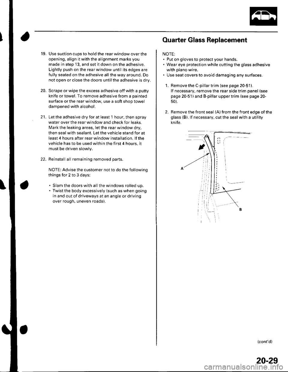
2. Remove the front seal {A) from the front edge of the
glass (B). lf necessary, cut the seal with a utility
knife.
(cont'd)
20-29
Page 688 of 1139
Glass
Ouarter Glass Replacement (cont'd)
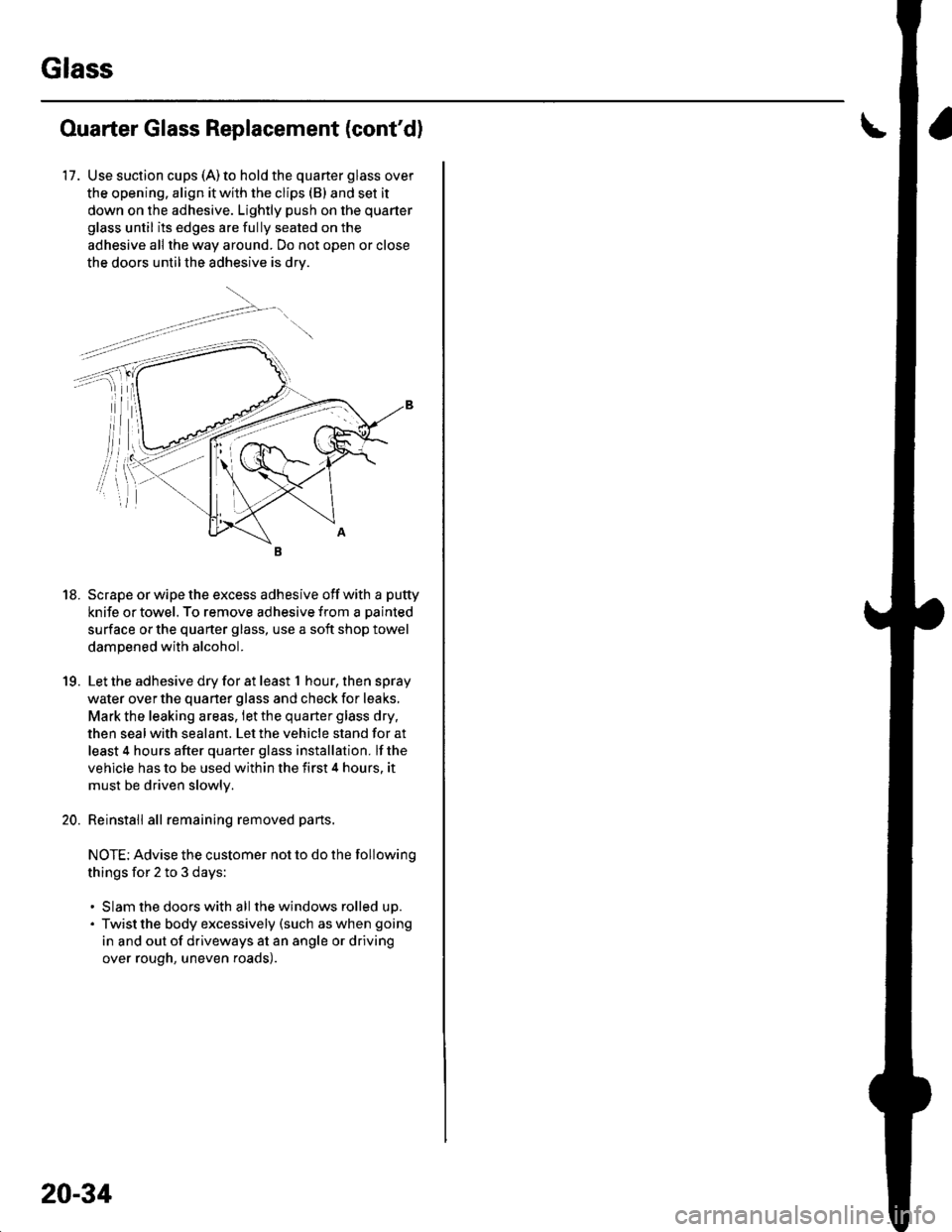
17. Use suction cups (A)to hold the quarter glass over
the opening. align it with the clips (B) and set it
down on the adhesive. Lightly push on the quarter
glass until its edges are fully seated on the
adhesive all the way around. Do not open or close
the doors untilthe adhesive is drv.
18. Scrape or wipe the excess adhesive off with a putty
knife or towel. To remove adhesive from a painted
surface or the quarter glass, use a soft shop towel
dampened with alcohol.
19. Let the adhesive dry for at least t hour,thenspray
water over the quarter glass and check for leaks,
Mark the leaking areas, let the quarter glass dry,
then seal with sealant. Let the vehicle stand for at
least 4 hours after quarter glass installation. lf the
vehicle has to be used within the first 4 hours. it
must be driven slowlv.
20. Reinstall all remaining removed parts.
NOTE: Advise the customer not to do the following
things for 2 to 3 days:
. Slam the doors with all the windows rolled up.. Twist the body excessively (such as when going
in and out of driveways at an angle or driving
over rough, uneven roads).
20-34
Page 764 of 1139
Openers
Hatch Handle Replacement
NOTE: Put on gloves to protect your hands.
1. Remove these items:
. Hatch lower trim panel (see page 20-53). Rear license trim panel (see page 20-98)
2. Remove the rear window wiper motor (see page
22-1461.
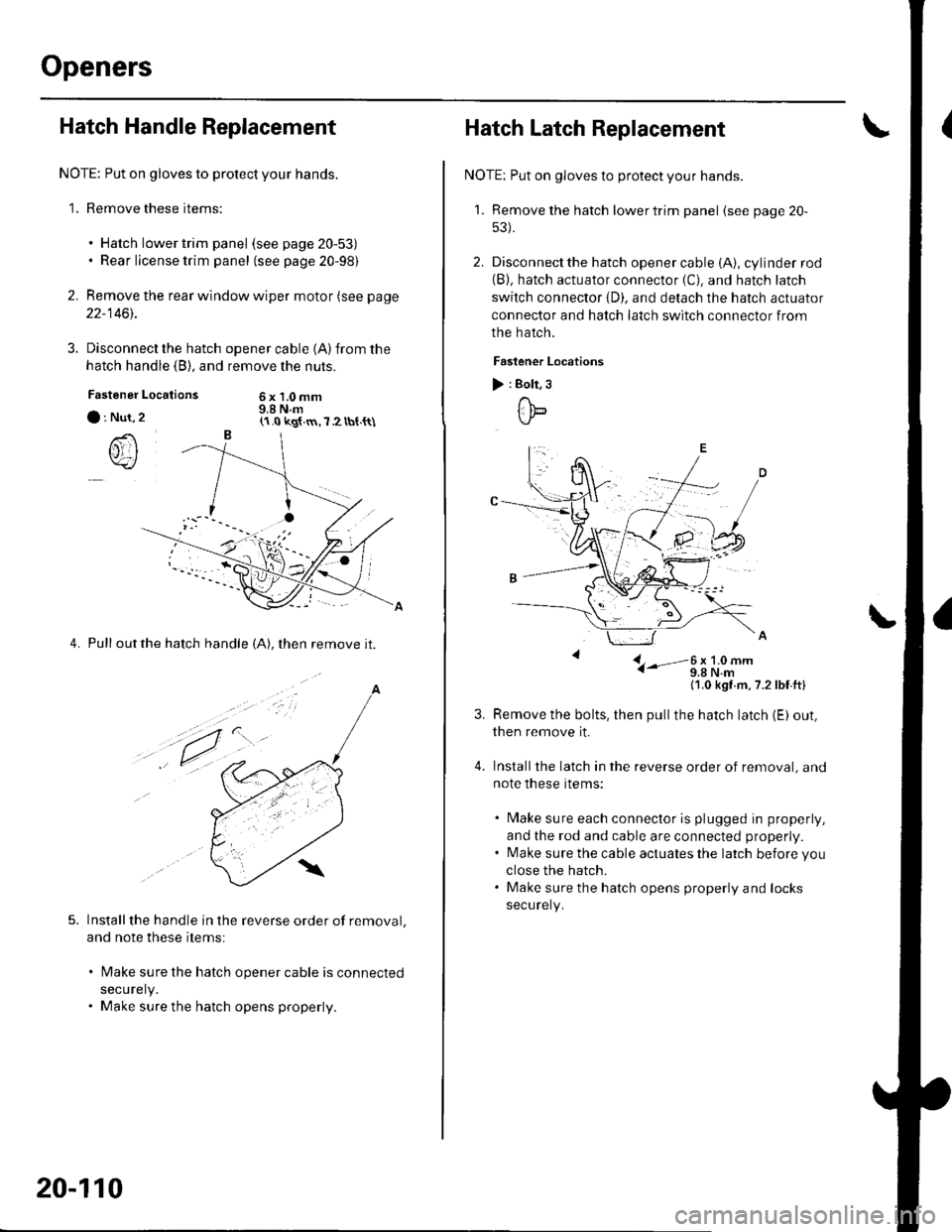
3. Disconnect the hatch
hatch handle (B), and
Locations
opener cable 1A)from the
remove the nuts.
6x1.0mm9.8 N.mFastener
a : Nut,
()rI
4. Pull outthe hatch handle (A), then remove it.
Installthe handle in the reverse order of removal.
and note these items:
lMake sure the hatch opener cable is connected
securely.
Make sure the hatch opens properly.
(1.0 kg{.m,7 2 tbt.{t\
a
,t.
20-110
Hatch Latch Replacement
NOTE: Put on gloves to protect your hands.
'1. Remove the hatch lowertrim panel (see page 20-
53).
2. Disconnect the hatch opener cable (A), cylinder rod(B). hatch actuator connector (C). and hatch latch
switch connector {D). and detach the hatch actuator
connector and hatch latch switch connector from
the hatch.
Faslener Locations
) : Bolt, 3
ttb
L- i-'-3;li9#-
11,0 kgt m,7.2lbf ftl
Remove the bolts, then pullthe hatch latch (E) out,
then remove it.
Installthe latch in the reverse order of removal, and
note these items:
. Make sure each connector is plugged in properly,
and the rod and cable are connected properly.. l\4ake sure the cable actuates the latch before you
close the hatch.. Make sure the hatch opens properly and locks
securely.
Page 780 of 1139
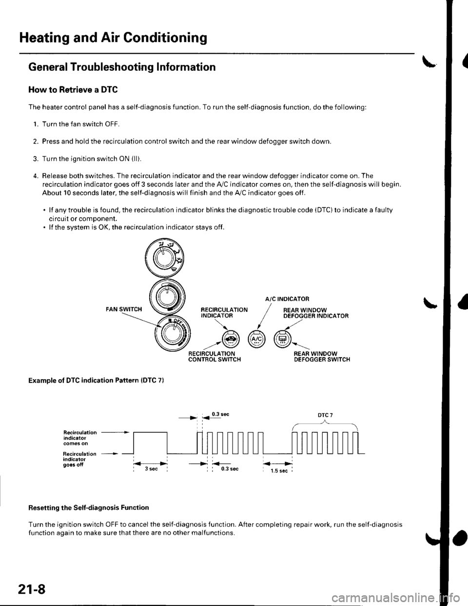
Heating and Air Conditioning
General Troubleshooting Information
How to Retrieve a DTC
The heater control panel has a self-diagnosis function. To run the self-diagnosis function, do the following:
1. Turn the fan switch OFF.
2. Pressand holdthe recirculation control switch andthe rear window defoooer switch down.
3. Turn the ignition switch oN {lli.
4. Release both switches. The recirculation indicator and the rear window defogger indicator come on. The
recirculation indicator goes off 3 seconds later and the Ay'C indicator comes on. then the self-diagnosis will begin.
About 10 seconds later, the self-diagnosis will finish and the A,/C indicator goes off.
.lfanytroubleisfound.therecirculationindicatorblinksthediagnostictroublecode(DTC)toindicateafaulty
circuil or comDonent.. lf the system is OK, the recirculation indicator stays off.
atc
@r
RECIRCULATIONCONTROL SWITCH
BECIRCULATIONINDICATOB
/A\
-:@
INOICATOR
REAR WINDOWOEFOGGER INDICATOR
REAR WINDOWDEFOGGER SWITCH
Examole of DTC indication Pattern IDTC 7)
DTC 7
Reseiting the Selt-diagnosis Function
Turn the ignition switch OFF to cancel the self-diagnosis function. After completing repair work, run the self-diagnosis
function aoain to make sure thatthere are no other malfunctions.
Recirculation +indicatot
Recirculation +indicalorgo6s oft----->
21-8
Page 783 of 1139
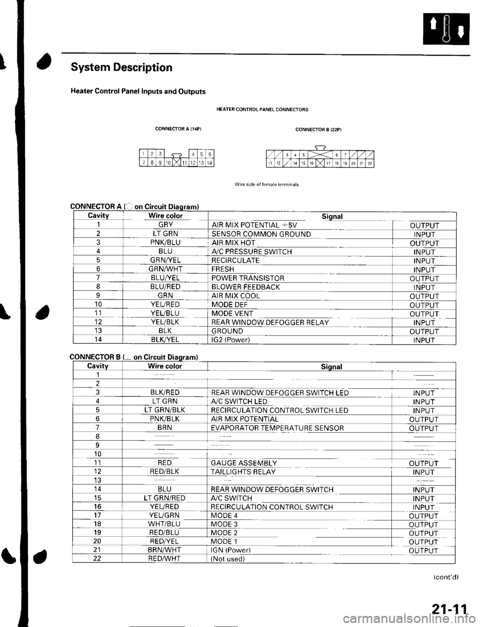
System Description
Heater Control Panel Inputs and Outputs
CONNECTOR A {r/rP)
CONNECTOR
CONNECTOR
HEATER CONTFOL PANEL CONNECIORS
CONNECTOR B (22P)
W re s de oitema eterm nals
Cavity Wire color_| \ln YAIR MIX POTENTIAL +5V
Sional
OUTPUT2LT GRNSENSOR COMMON GROUNDINPUT3PNK/BLUAIR MIX HOTOUTPUTBLUA,/C PRESSURE SWITCHINPUT5GRNA/ELRECIRCULATEINPUT6GRNA/VHTFRESHINPUT7BLUI/ELPOWER TRANSISTOROUTPUT8BLU/REDBLOWER FEEDBACKINPUTIGRNAIR MIX COOLOUTPUT10YEL/REDMODE DEFOUTPUT11. YEVBTU
YEL/BLK
MODE VENT
REAR WINDOW DEFOGGER RELAY
OUTPUT
INPUTBLKGROUNDOUTPUT14B LK/YELlG2 (Power)INPUT
Bon
CavityWire colorSiqnal1--T
2
3BLIVREDREAR WINDOW DEFOGGER SWITCH LEDINPUT
4LT GRNA./C SWITCH LEDINPUT
5LT GRN/BLKRECIRCULATION CONTROL SWITCH LEDINPUT
6PNVBLKAIR MIX POTENTIALOUTPUT
7BRNEVAPORATOR TEIMPERATURE SENSOROUTPUT
8
9
10
GAUGE ASSEMBLYal' 'TDr ri11RED
RED/BLKTAILLIGHTS RELAYINPUT
14BLUREAR WINDOW DEFOGGER SWITCHINPUTicLT GRN/REDA/C SWITCHINPUT16YEVREDRECIRCULATION CONTROL SWITCHINPUT17YEUGRNMODE 4OUTPUT18WHT/BLUMODE 3OUTPUT19RED/BLUMODE 2OUTPUT20RED/YELMODE 1OUTPUTBRN^,^/HTIGN (PowedOUTPUT22R E DA/r'HT(Not used)
(cont'd)
21-11